 Kn/vD
Kn/vDBefore I started designing various cards, I made this template which removes for me the boring parts in the job. I use Altum in my designs, hence the file here is for Altium, but it can (probably) be exported to another software as well.
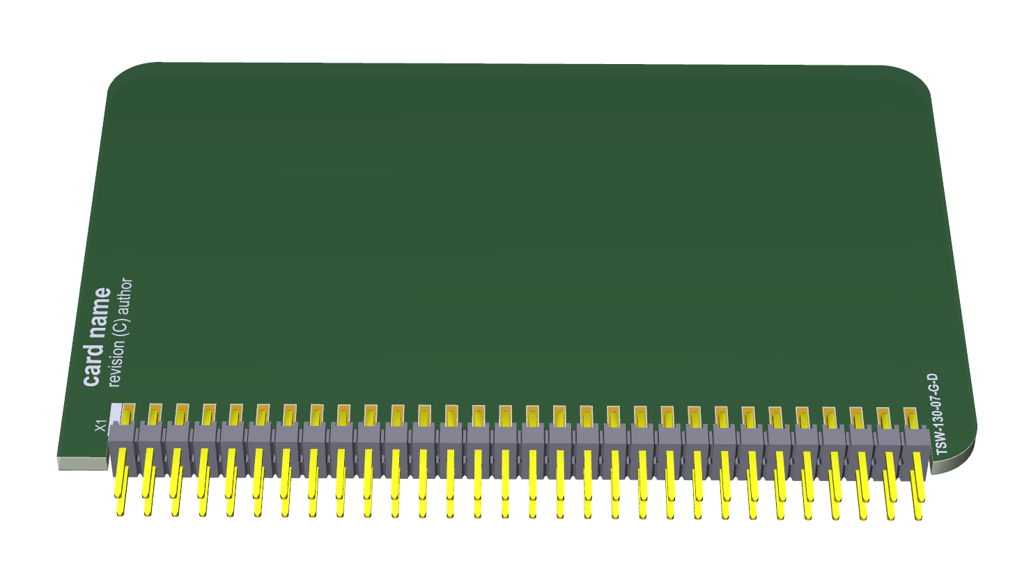
This is what a blank "standard" card for Base 18 looks like:
And looking from the side:
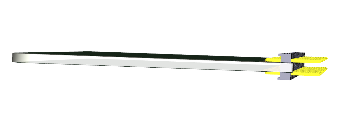
A standard vertical through-hole header slides into the PCB and is soldered in surface mount way.
The template card has dimensions 86 x 55mm.
The best PCB thickness for this method is 1.8mm, but the standard 1.6mm works perfectly fine too. I have specified some header model from Samtec, simply because they have an excellent configuration tool. In reality any 60-pin dual row header, ideally with 5.84mm contact height, will do exactly the same job. I had difficulties finding exactly 60-pin headers, but the 80-pin ones are quite common and cheap on Aliexpress and everywhere else, so I took a bunch of those instead to cut them to size whenever that will be needed.
Pin one is on the top side of this board and where it is marked with a straight angle instead of rounded like elsewhere.
The schematic for the bus connector:
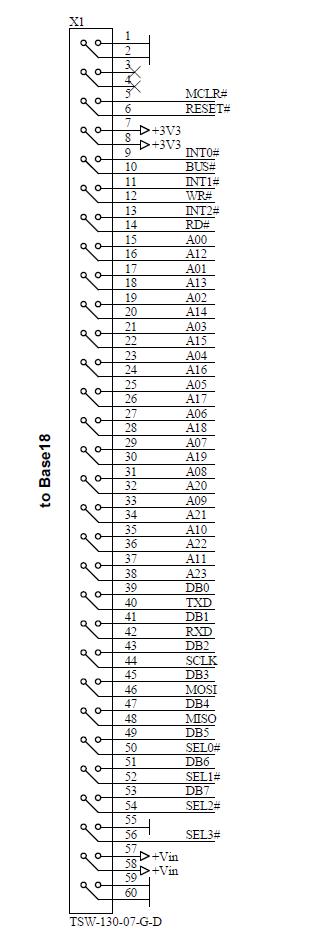
The bus has two separate reset signals - MCLR# and RESET#.
The first one applies to the PIC18 on the main board only, while the second one is general for the entire system. The RESET# signal also takes precedence over MCLR# in such way so when RESET# is brought low, MCLR# also becomes low, but if MCLR# is low, it does not affect the state of RESET#. Thus a controller card could disable the on-board PIC18 by simply holding the MCLR# in low and then take over the entire bus by installing a different processor instead.
Another part to mention are the unoccupied pins 3 and 4. The reason for that is to mitigate any potential harm coming from reverse installed cards. In this case - the "dangerous" lines carrying the raw input voltage (anything between 5V and 14V) will fall into the unconnected slots.
Pin 55 on the bus also has the specific purpose to prevent reverse connected cards. Its 180 degree counterpart is exactly the RESET# signal, so any (assuming properly designed) card that is connected reverse on the bus will cause the signal RESET# being kept permanently low, thus preventing any unwanted damages to the main board or the controller card.
I am currently making the first generation prototypes of the main board and several cards. Once they turn up here and hopefully work, I will start publishing more detailed schematics.
And finally, the PCB drawing for the card template:
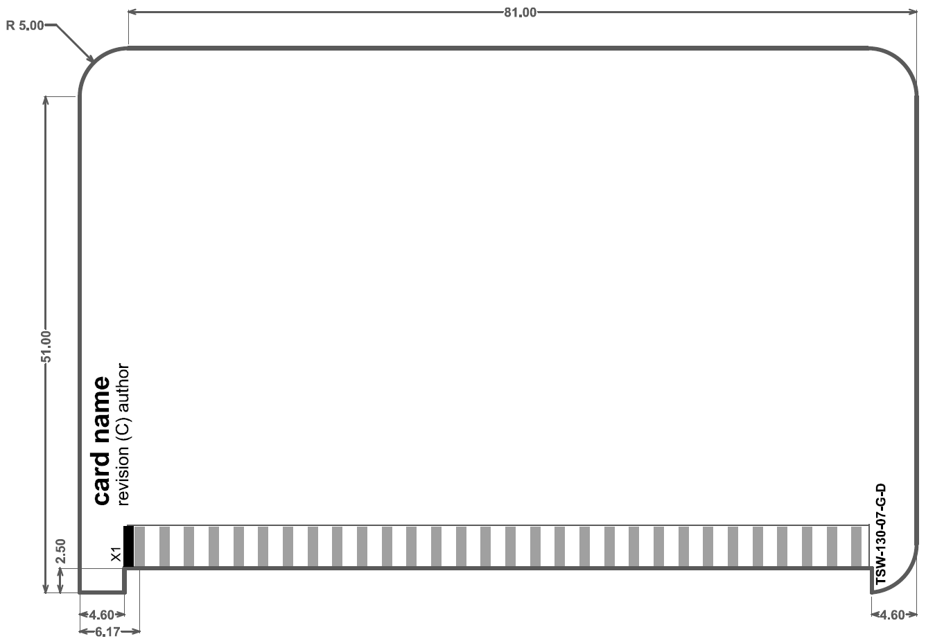
This template is available as Altium PCB file in the project files section.
Discussions
Become a Hackaday.io Member
Create an account to leave a comment. Already have an account? Log In.