 Andrey V
IOTON MICRIO MPU Quick Start and Hello World
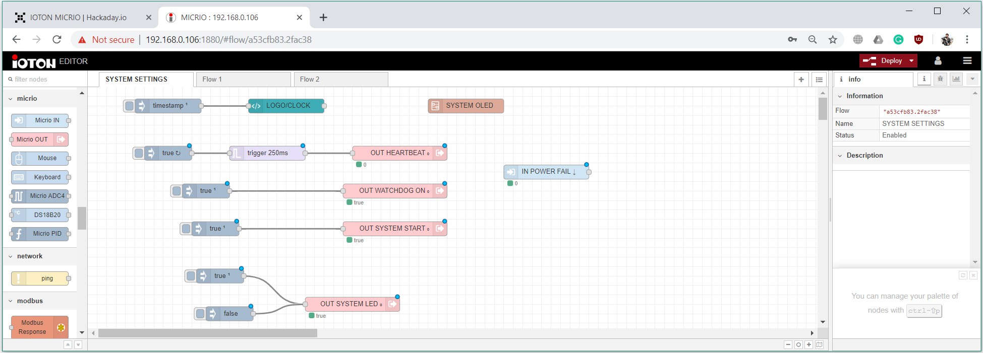
This video is about very basic IOTON MICRIO functionality. How to connect devices, program system via EDITOR, control it via USER DASHBOARD and via E-mail messages.
IRL
Some modules (not all).
Before I start the project description let me introduce the first industrial project on IOTON MICRIO equipment.
My old school friend is the CEO of company produced bioreactors. For one of his projects he asked me to make a system to control 3 big fans (on/off by schedule) and one pump motor. RPM for this pump motor must depend on atmospheric pressure and temperature, and calculated with the interesting formula (I can't post it here because of NDA). I solved this problem in one day. IOTON MICRIO MPU takes atmospheric pressure and temperature data from the INTERNET and control motor by MODBUS protocol (RS485 PHY). On this moment system works around 3 months w/o any problems. The schematic is simple:
HOW I DID IT ALL
Please, excuse me for any errors in the text, English writing is not so simple for me.
Base principles:
At first, I identified five base principles for the whole system:
1. Any input or output must be galvanically, optically or mechanically isolated from the Microprocessor Unit (MPU)
2. Keep the size as small as possible.
3. Keep it simple, stupid.
4. Reliability is more important than functionality.
5. All modules must be cross interchangeable.
Programming environment:
Luckily I found Node-Red from IBM guys. It's a really great and simple programming environment for the IOT devices. It works flawlessly on Raspbian and has great support from developers on their forum.
Schematics:
It was not so challenging for me. I have enough experience in it. Also, I have experience with repair different models of PLCs so I know base principles for safety, reliability, and functionality.
A little challenge was to find the solution for RS485 and 1-wire galvanic isolation. I used an isolated DC-DC converter and Analog Devices transformer isolators.
PCB tracing:
It's not rocket science because only a few tracks in the whole project needs impedance match. Only 2 things will need to keep in mind - max trace current and enough clearance between protected and unprotected parts of PCB.
3D modeling:
It was challenging. To keep the size as small as possible I stacked PCB's vertically. And had many problems with connectors placements and PCB's shapes. Also always need to keep in mind, how to assemble the final product.
DIN enclosures:
I use a standard 1U, 2U, 3U 57mm height DIN rail enclosures. Only thing I need to buy is CNC milling machine for milling ports holes.
Enclosure labels and other graphical work:
All labels I did in vector form. Because it's scalable and good for printing. The labels are printed on Lomond transparent self-adhesive film. One little problem - for rendering I was need to convert it to raster.
PCB stencil:
PCB stencils are costly. If you wondered why I will explain. The stencil itself doesn't cost so much (6 - 30$ depends on size and electropolishing) but my Chinese fab carefully packs each stencil in own box and with the box it has weight 900 grams in my case. And delivery for 1 stencil is around 30$(for 17 PCB in my project if I order stencil for each PCB it will cost around 750USD for all). A clever way to save money - merge different boards gerbers in one big gerber and order one universal stencil for all boards.
PCB ordering:
I ordered PCB's on JLCPCB.com. I'm working with this fab a long time and I like the quality and speed of this fab. Once I had a problem, my order delivery was delayed for 15 days because of Chinese New Year. For this project, I ordered PCB's three times because of board revisions.
Parts ordering:
Full BOM for all modules consists of 250+ different! parts. I ordered parts on Ali from 27 shops... It's so annoying.
PCB assembly:
It's simple if you have a stencil. Just place components correctly on the PCB and put PCB in the soldering oven. I use Puhui T-962 oven.
FRITZING:
I made FRITZING models for most of the modules and some electrical stuff. You can find FRITZING bin with modules in attached files.
MODULES DESCRIPTION:
IOTON MICRIO MPU
MICRIO MPU is the heart of all system. It's based on Paspberry Pi Zero W and has a large number of different options and interfaces.
Boards:
In one 2U (96x36.5x58mm) DIN rail enclosure 6 PCBs were placed, from top to bottom:
- OLED board
- Top board
- 868mHz radio board
- Interface board (1 LAN, 2 USB, 1 UART)
- Raspberry PI zero W
- Base board
Basic connection diagram:
Features:
- Hardware WATCHDOG
- RTC with external battery
- UPS (fully analog circuit for reliability)
- Battery controller (prevent battery from full discharge)
- UPS output for power external devices(like MODBUS slaves) from UPS.
- Isolated RS485 port (565Vpeak AC Voltage Bipolar Waveform)
- Isolated 1-wire interface (Viorm 560Vpeak)
- Isolated 5V 50ma output for external sensors
- SMA antenna connector (for WIFI antenna or 868MHz antenna)
- 2 USB2.0 ports with surge protection
- LAN port with external transformer protection
- 20 pin port for I/O modules (16GPIO, I2C, 5VDC)
- Radio module (up to 3000m)
- Terminal connector
Programming environment:
As I wrote before I'm using Node-Red software. IOTON Editor - just slightly modified Node-red with specific MICRIO nodes and subflows.
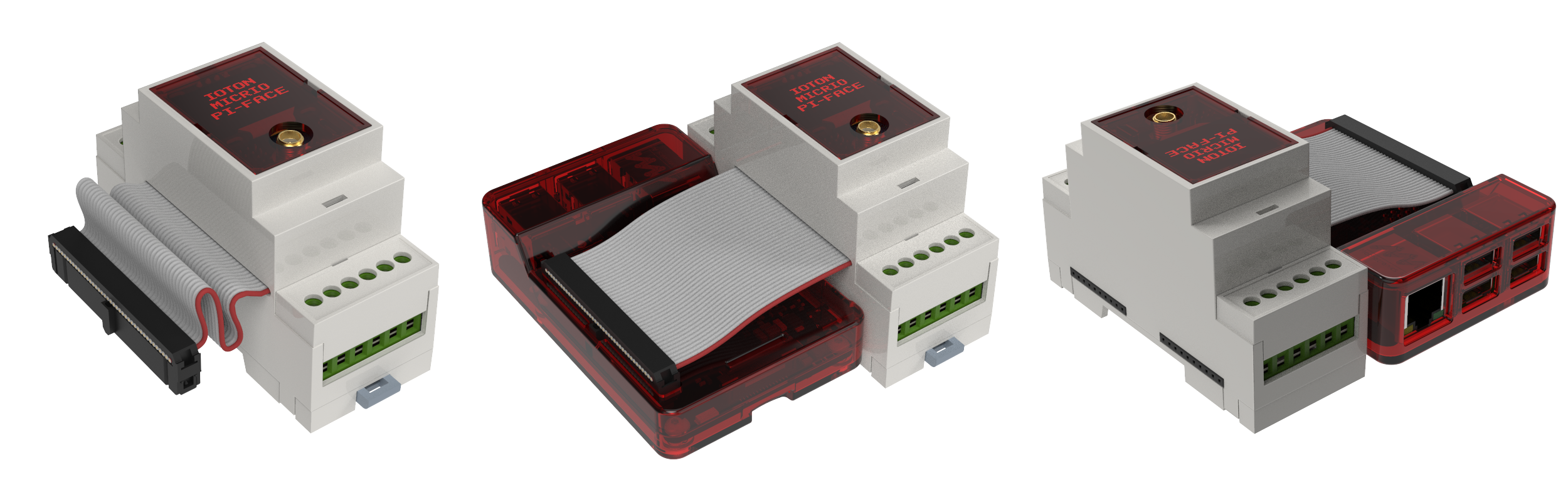
IOTON MICRIO PI-FACE
It has the same features as MICRIO MPU, but uses Raspberry PI 2,3 or 4 as microprocessor unit.
DIGITAL INPUT MODULES DI8.1, DI8.2
Digital input modules are designed to connect to IOTON MICRIO MPU directly by 20pin(DI8.1) or 12pin(DI8.2) interface connector. For MICRIO MPU it is possible to connect 2 DI8 modules and get up to 16 digital inputs.
As I wrote before, I need digital input module with universal inputs, so I did it!
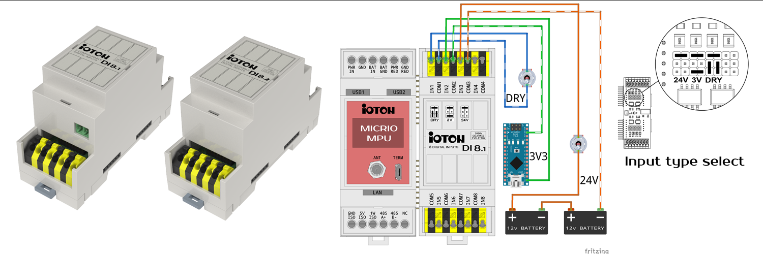
As you can see on pic. it is possible to connect different types of switches or sensors. On this example:
- IN1 configured as "DRY CONTACT" you can connect switch or momentary button directly, without any additional voltage source.
- IN2 configured for voltage source from 3VDC to 12VDC you can connect to this input low voltage devices for example 3.3V arduino nano.
- IN3 configured for voltage source from 12VDC to 28VDC you can connect to this input any 24 volt industrial sensors with digital outputs.
All inputs have optical or galvanic isolation.
DIGITAL OUTPUT MODULES DO8.1, DO8.2
Digital output modules are designed to connect to IOTON MICRIO MPU directly by 20pin(DI8.1) or 12pin(DI8.2) interface connector. For MICRIO MPU it is possible to connect 2 DO8 modules and get up to 16 digital outputs.
Those modules work with voltages from 3V to 28V.
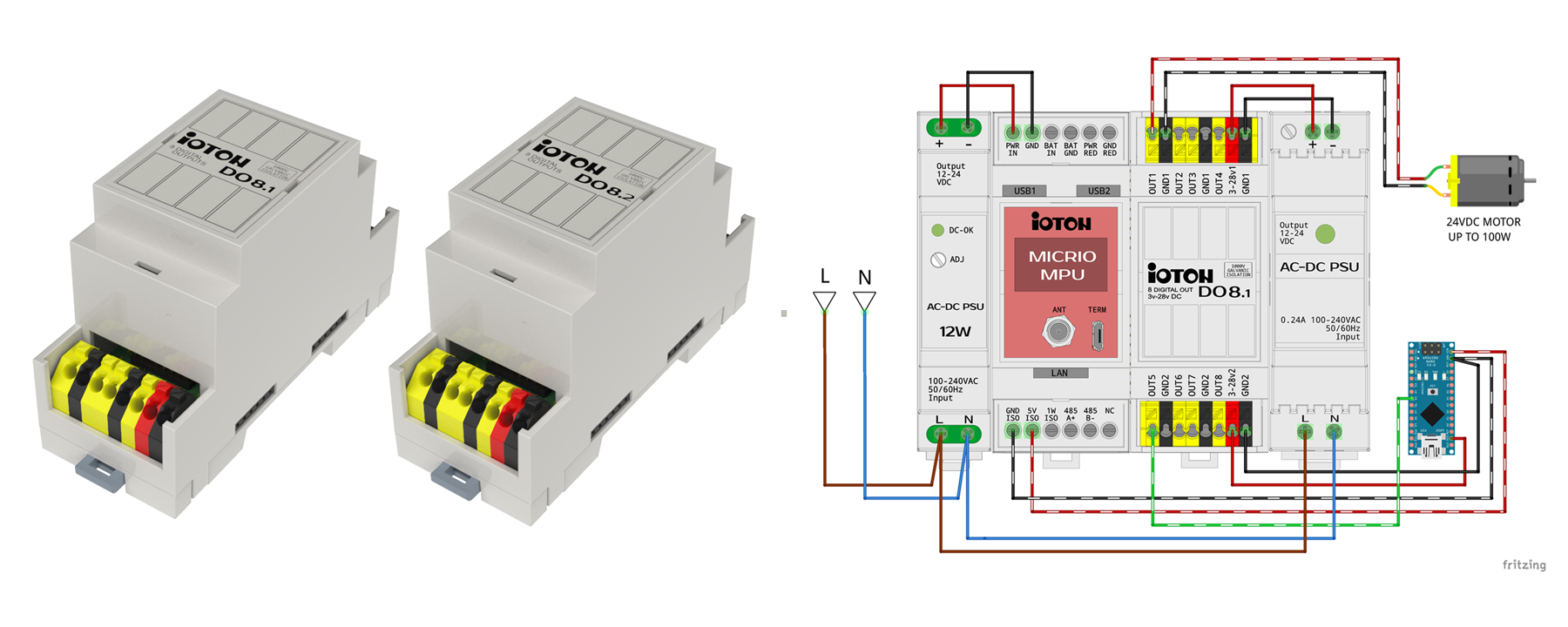
OUT1 can power DC motor up to 100W 24VDC
OUT5 can work with low voltage and compatible with 5V or 3.3V interfaces
All outputs have optical isolation.
DIGITAL INPUT/OUTPUT MODULES DIO4.1, DIO4.2
Digital input/output modules are useful if you need only 4in and 4out, or you need different qty of inputs and outputs such as 12in 4out or 12out 4in for one IOTON MICRIO MPU.
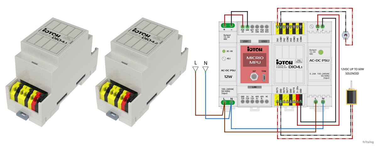
Digital inputs specs is the same as in DI8 modules. Digital outputs specs is the same as in DO8 modules.
All inputs and outputs have optical isolation.
RELAY MODULES RLY4.1, RLY4.2, RLY4.3, RLY4.4
Relay modules used for work with the hi voltage loads directly. Each relay can work with up to 6A 250VDC load. It is possible to connect up to 4 relay modules to IOTON MICRIO MPU and get 16 relay outputs.
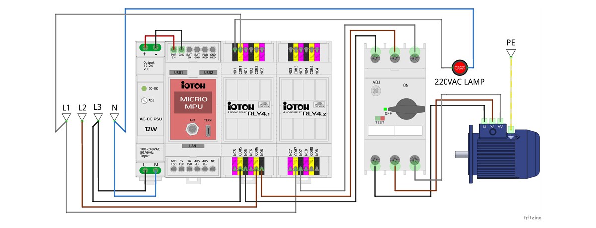
This is an example, how to use it with the induction motor and 220V indicator lamp.
4-CH UNIVERSAL INPUT 16bit ADC MODULE
To measure voltage or current you will need an ADC (Analog to Digital Converter). Professional PLCs mostly designed for standard signal values:
0-10V for voltage.
4-20ma for current loop
0-20ma for current loop(rarely because of 0 calibration problems)
When I designed my ADC module I thought, maybe I can add some features for compatibility with professional and consumer sensors (like different sensors for Arduino e.t.c), because professional devices are expensive. And I did it.
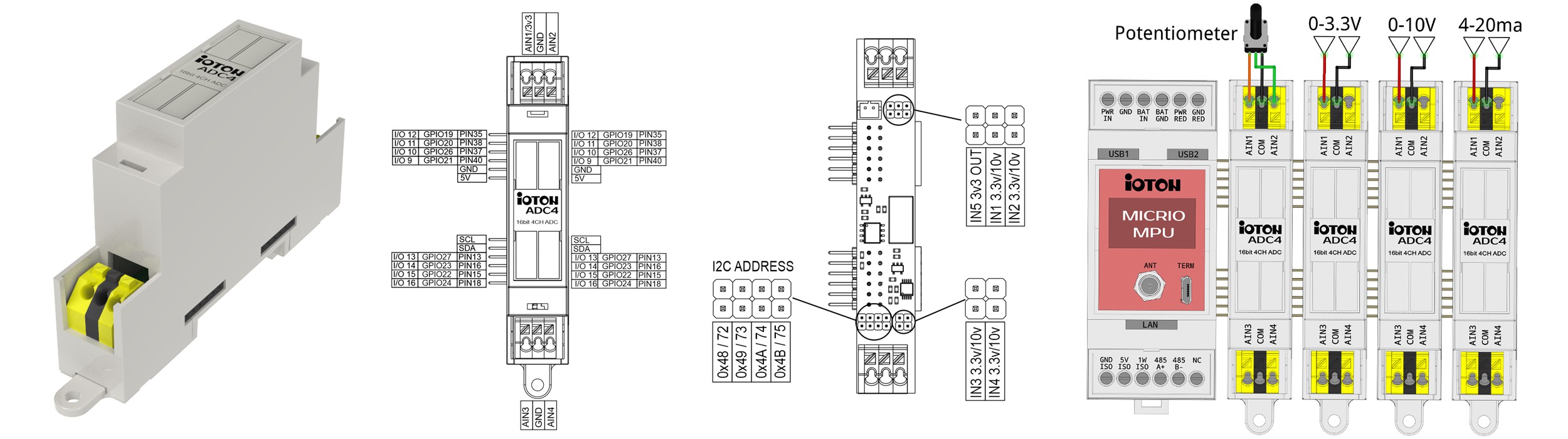
As you can see, an ADC4 board has 3 groups of jumpers:
Top - two right jumpers for voltage select, left jumper connect 3.3v to CH1. It is very convenient if you need to control something via simple potentiometer without additional voltage for it (you can see this connection on the left pic.)
Bottom left - to set I2C address (it is possible to connect up to 4 ADC4 to one MICRIO MPU and get up to 16 ADC channels).
Bottom right - voltage select for CH3&CH4
Any input of any ADC4 can be switched to any of this modes:
0-3.3V (with internal ADC PGA(Programmable Gain Amplifier) you can measure voltages as low as +/- 256mV for full scale)
0-10V
4-20ma (you will need an additional 120R resistor)
ADC4 is fully galvanically isolated from MICRIO MPU by both I2C and POWER lines. Maximum isolation voltage (Viorm) - 560VAC.
IOTON MODBUS MCU RS485
MODBUS MCU RS485 is an interface to connect IOTON modules (DI8, DO8, DIO4, RLY4, SSR4) via MODBUS protocol by RS485 PHY.
This module has a big difference from all I've seen on market. User can set 4 groups of GPIO contacts to act like inputs or like outputs independently. To add this functionality I used 4 modbus registers (one for each GPIO group). If you put 0 in those registers GPIOs acts like inputs (for DI8 or DIO4 modules), if you put 1 - GPIOs acts like outputs and allow to connect (DO8 or RLY4 modules).
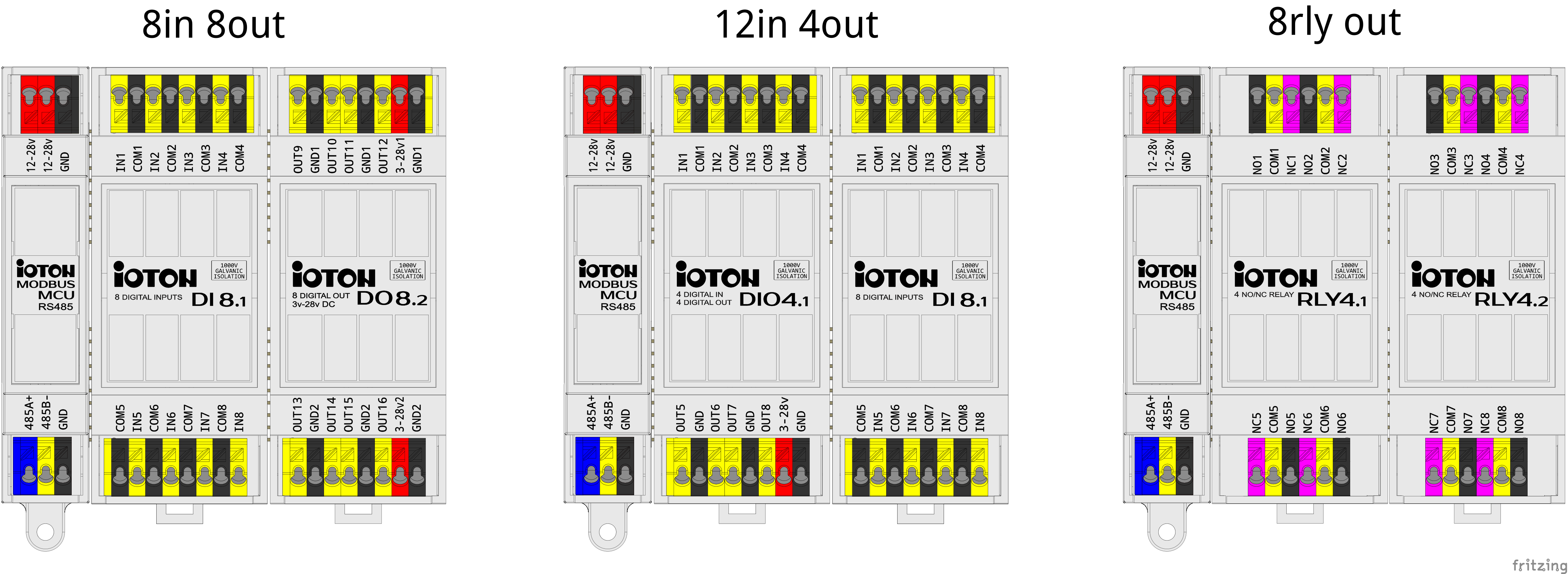
As you can see on this example, you can get any IN-OUT configuration with absolutely same MODBUS MCU controller.