 Patrick Hickey
I bought 2 different readout displays with the aim of figuring how to light them up using modern LED technology and microcontrollers, and eventually build some clocks / timers resembling the original units in the firing room. At over $200 per digit it would be prohibitive to build a clock using these rare artifacts, in any case, I doubt there will be many more available for sale or that still exist. Hopefully through the convenience of 3-D printing and some hacking I can build enough replicas to build a 6 digit clock and make them available for other people to incorporate into other projects.
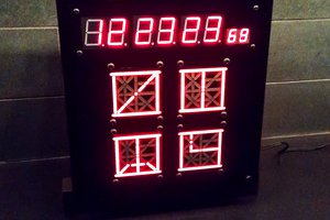
These displays are estimated to be well over 50 years old, and according to the seller originated from collection of Charles H Bell, who was apparently in charge of decommissioning / updating the control room for the KSC visitor center / museum. Initial inspection leads me to believe that they use 7 incandescent lamps to light up the individual segments, although I have yet to determine what type – there were very few early LEDs available at the time ~1969.

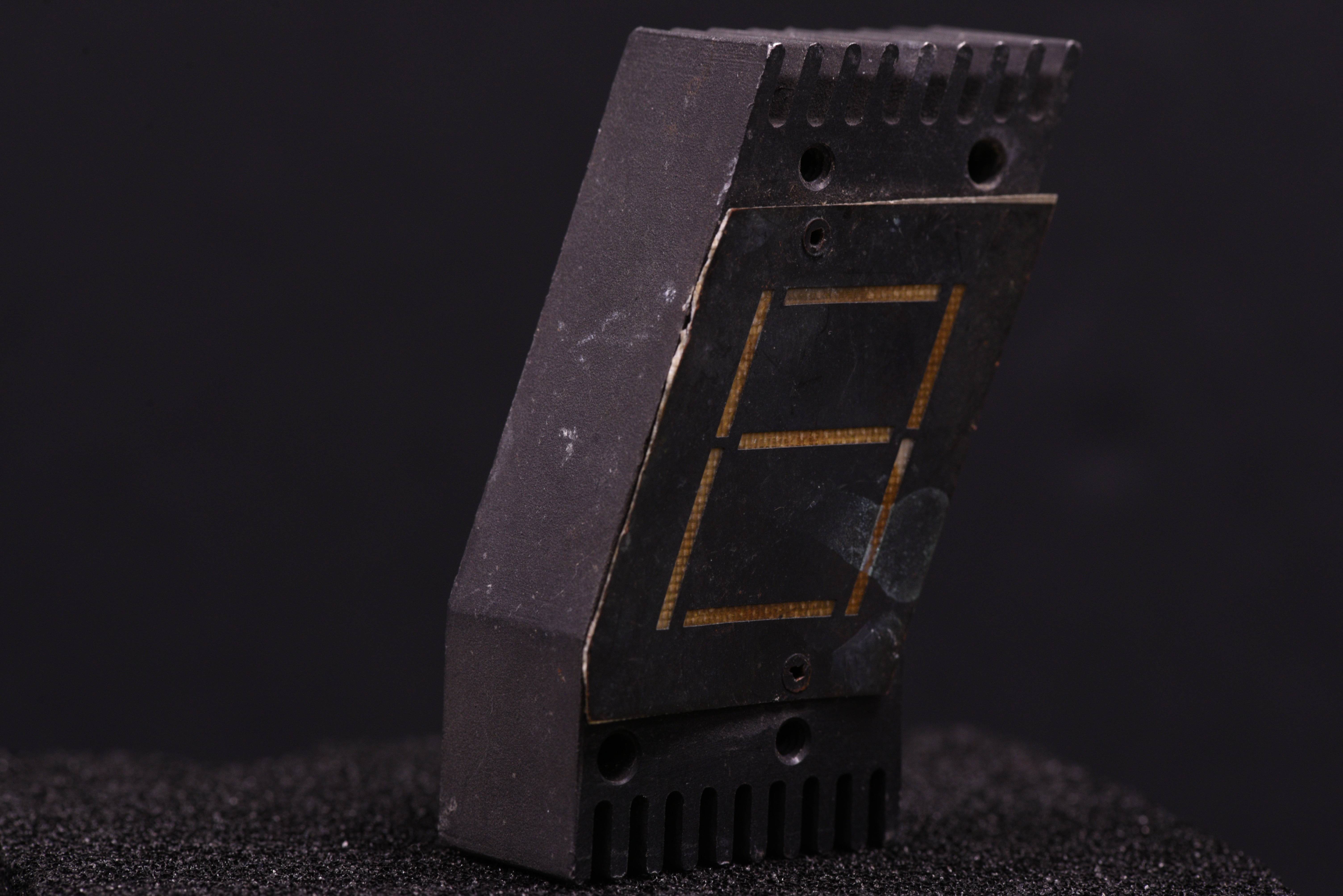
The displays are machined from solid chunks of aluminium and have heat sink/cooling fins – presumably if they did use incandescent lamps, these would get hot and needed to dissipate the heat.

The smaller type of the displays (I will refer to as TYPE A) uses a metal plate with cut-out mask and some kind of diffuser - it is very thin and looks like fibre glass or a very PCB. I am not sure how the mask was created but it looks like it may have been etched from the metal material which looks like brass or copper. The mask is riveted to the main body.
Initial ideas for producing a replica assembly consisting of 3 main parts.
(1) Front face mask:
- (a)Multi layer mask with laser cut vinyl stuck on thin diffuser material.
- (b)Black PCB with pre-cut cut apertures for segments
- (c)Laser cut acrylic filled with opaque epoxy filled segments
(2) Central body/housing:
3D printed plastic body with holes for lamps; CNC aluminium would be awesome.
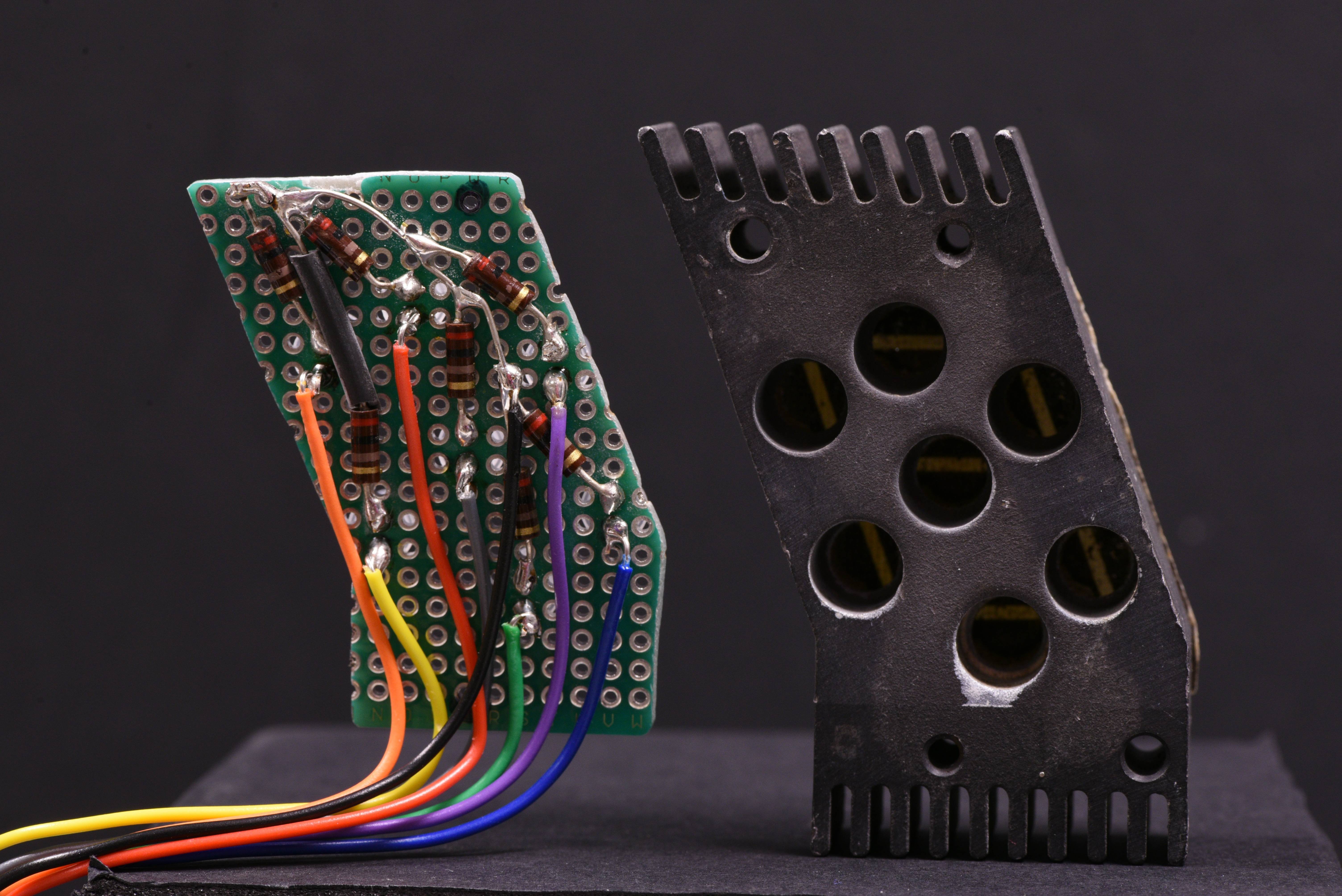
(3) Back plate PCB
To house the LED lamps, resistors and wiring. The PCB would connect through a bundle of 8 wires. Further improvements would be to put a dedicated microcontroller on each digit, like the Texas Instruments TIL-311 or Hewlett Packard latched BCD displays to reduce the wiring burden.
Lighting up the original "Type A" display.
After various experiments shining LEDs through the holes, I decided to use a diffused 5mm white LED, and got to work marking on a prototype PCB the hole positions. The next task was to layout LEDS as close to the hole positions and connect in a common cathode configuration. I soldered 7 current limiting resistors (200 Ohm) directly to the back, and made a connection loom via single core hook up wires.


Conveniently I had already built a tester based on an Arduino pro mini for 7 segment numitron / pinlites (project write up coming soon) so have used this for initial testing.


Further development is underway, I have various photos of the segments lit up from 0-9 and some alphanumeric characters in testing – perhaps someone could make a virtual clock using these images. I would very much welcome comments and suggestions… are there any NASA engineers out there?!
The larger displays (referred to as TYPE B) use internal reflected light scattering to illuminate the segments and the cavities inside are painted with white paint..

Presumably a side emitting lamp would work best for this design. For future development I might consider using a diffused epoxy resin to fill the segments, a sheet of paper or perhaps some opaque laser cut acrylic lenses .
")


 RIUM+ (Mike Ando)
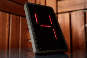
 Madison
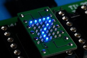
 Mile
Mile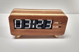
 Spencer
I love these old displays (even though they are electrically thirsty and get awfully hot). Re-creation of the designs is one of my great vicarious joys - and one day I may even reproduce some Dekatron counter tubes using LEDs.
Having had some experience with this style of display (but not these actual units), the lamps are probably: 90V wire-ended neon tubes with thoriated electrodes were often used. The 1400 Ohm 250mW resistors on the original would suggest this to be the case.
Under-driven 36V or fully driven 28V wire-ended peanut bulbs might be used, but these wouldn't require resistors, and would almost certainly overheat the display regardless of the cooling fins.
The diffuser/masks on your Type A will be ~0.25mm glass fibre PCB with chemically blackened etched copper masks. Multi-message status arrays using this style of mask used to be popular - 1 lamp per message.