 krzysztof krzeslak
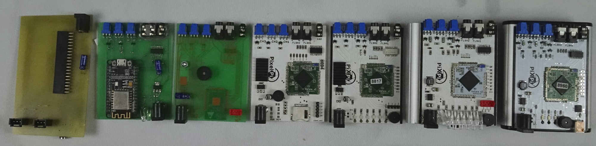
Hello in this log I wanted to talk a bit about initial goals which I had for controller, design process, prototyping and also I will try to explain what was rationals behind each taken design decision.
As i mentioned in project description I started working on this controller after gaining some experience with high speed photography using Arduino and beginnings was hard, but anyway i enjoyed playing with this project so this was first and very important step - to get fun from what you do :).

After first experiments i already had some thoughts what could be improved to make this works easier and better.
My initial thought was that it will be good to had possibility to easily tweak delays in program, electrical connections wasn't reliable at all, as well using optical sensor for detecting droplets also wasn't guarantee of good timing and repeatable results, so I had something to work on.
Then I came with idea of using RaspberryPi on which I could run some web interface which will be accessed with smartphone browser. From web interface [python]script was run, this script through RPi gpio`s and Mosfet shield will drive solenoid valve to make some droplets. At this time I already knew that utilising solenoid valve is right way, as I dig a little in internet and it seemed common solution for such use case, but I didn't saw anyone using RPi nor Python for it which can be understood, as it can be described as "taking sledgehammer to crack a nut", but I wanted to use it it as i could put some web-interface on it quite easily ...and i had a RaspberryPi lying on shelve which i wanted to use for something :p
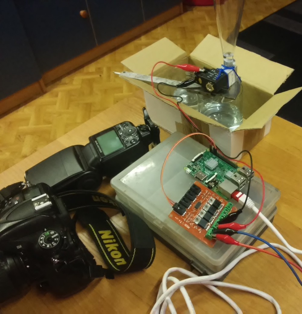
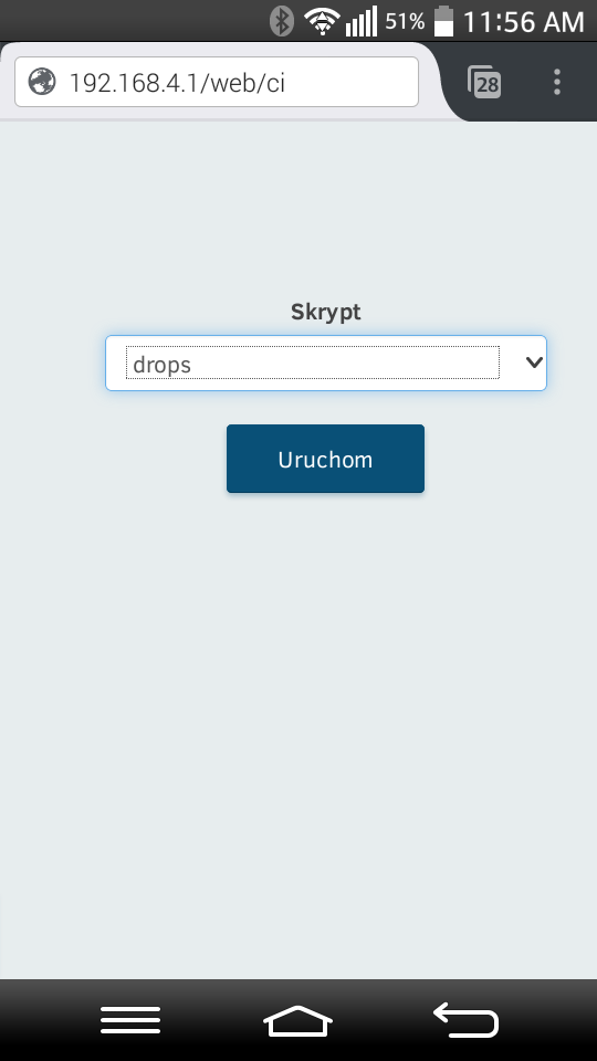 Web interface which i used back then, time for quick lesson of polish :D Skrypt=Script, Uruchom=run, also it was lacking any configuration, just run selected script, so in effect I ended up hooking laptop with ethernet cable and direct script editing.
After this experiments I started thinking about creating some dedicated controller which I would like to use... and after some time I really started working on it ;)
I set some initial goals for controller:
1. Can be quickly and easily set-up
2.Can be reconfigured using smartphone, without need of use computer.
3.Can be used without knowledge in programming nor electronics.
4.At the same time will not limit those with some technical knowledge, so let's say to be hacker friendly and possible to extend in much as possible ways.
Withing above goals I came to some design decisions:
1. Single controller board which will have possibility to connect modules, provide supply for them and (of course) basic control signals.
2. Controller board need to be equipped with Bluetooth or Wi-Fi connectivity, so it can be controlled from smartphone Application.
3. Smartphone application need to utilise some graphical configuration/programming interface to make it easy to use, so I dig a little and when typed "graphical programming library" in Google search I discovered Blockly library(by the way, also created by Google) , also this affected final choice of programming language which I will need to run on controller board, as it will be hard to compile code on smartphone I needed language which will have possibility to execute code without compiling(from string) I already had experience with python and knew that python have "exec" function, so on smartphone I will need only to create Python script as a text.
Because of this decision i needed to look for (micro)controller which will be able to host Python.
4. Project will be opensource.
Withing this conclusions in mind, finally i started working on prototypes:
Approach 1: Hard beginnings
Heheh beginnings was hard, this was not working at all, but at least I learned something with it
first of all... no more etching :p
second even Rpi zero will be too big and complex for such use case I needed to look for something else.
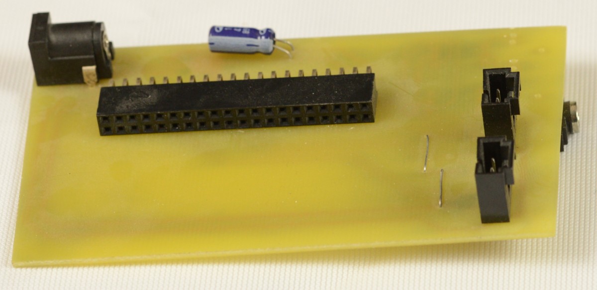
Approach 2: Hmm This isn't how i Imagined it.
After i came to conclusion that Rpi will be too complex for such task I decided to give a try of esp8266 as it was equipped with WiFi and it's able to run MicroPython, but as you can see, also this approach was... there's was an issues I think biggest of them was that i connected some pin which should be connected, so in effect I was not able to access serial of esp.
Conclusions was following:
- I rather should use "plain" esp board instead of module, as to keep WiFi antenna close to edge of board usb will be directed in direction that is not handy to use.
- If pins which shouldn't be connected cannot be used I will have too less gpio's on esp8266
Approach 3: There's some progress

This time it was better ...it was even working and was not so bad, for this iteration i abandoned esp8266 and moved to esp32 which have more gpio`s, also instead of module with serial/usb chip I used plain esp32 and just connected external converter for programming purposes.
At this point I started to working on Android application, as well on proper application for Android and after some time I was able to connect them:

Time for conslusions:
There was significant issue with esp32/MicroPython it is single threaded, so for example when i sent script, there was no communication between controller and Android App possible until script was finished, so it introduced a lot of problems, how to stop script or what in situation when user will sent script which will had infinite loop in it.... I realised that i need multitasking, one task/thread for handling communication and controlling execution, second for execution.
Also another reason behind that I abandoned esp32 quite easily as I not liked one more thing about it, programming and debugging of it was not so easy scripts, as on RasPi/Linux.
Approach 4: Big step forward
So finally I found VoCore2, it's a coin sized Linux computer, equipped with WiFi, 580mhz Mediatek SoC, lot of gpio`s, it's available at affordable price level and it's fully open-source as well open-hardware(board design is impressive), so this is why praise it so much ;)
After moving on with VoCore2 I started to writing new control application for a board, which was running multi-threaded server, so it was able to respond on requests even control script was running, also I needed to create library for interfacing with gpio.
Also as you can see at this time i was naming this project "PixelPi".
Conclusions:
- Mistake in design, Ethernet ports cannot be used as gpio's(those which starts with P0..), so I got only one port which was working in it.
- sd card is not really needed for my use-case
- At this moment I also started thinking about adding possibility of control some motorised modules, so I needed a little more sophisticated communication interface for module.
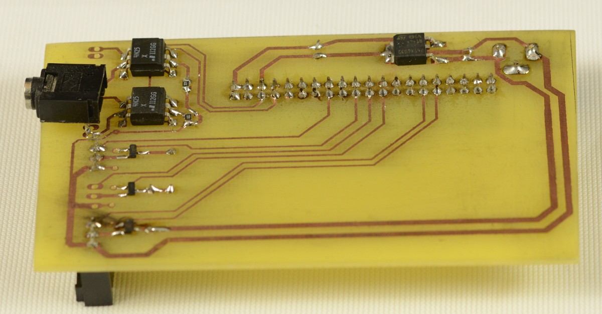
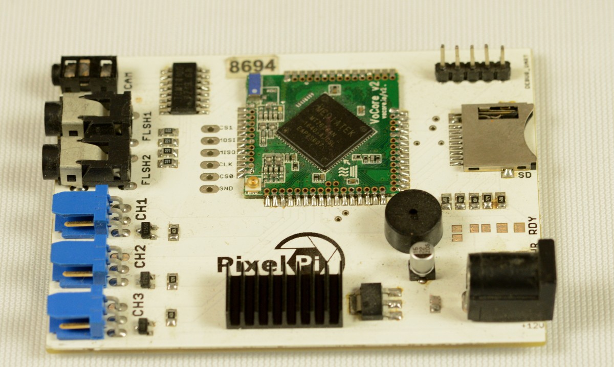
Approach 5: Some tweaks
So in this approach:
-SD card connector was removed
-led's was added for state signalling
-Added circuit for one-wire/uart conversion on port red, more on this here:
https://www.maximintegrated.com/en/app-notes/index.mvp/id/214
so now port red could be used as input, output and com for one-wire communication.
-Also some gpio connector/pins was added for future uses
Conclusions:
-voltage regulator circuit should be replaced, as there are better ways than heat-sink on voltage regulator.
-ports of VoCore are fragile so should be protected somehow as I killed this board finally with voltage spike from solenoid.
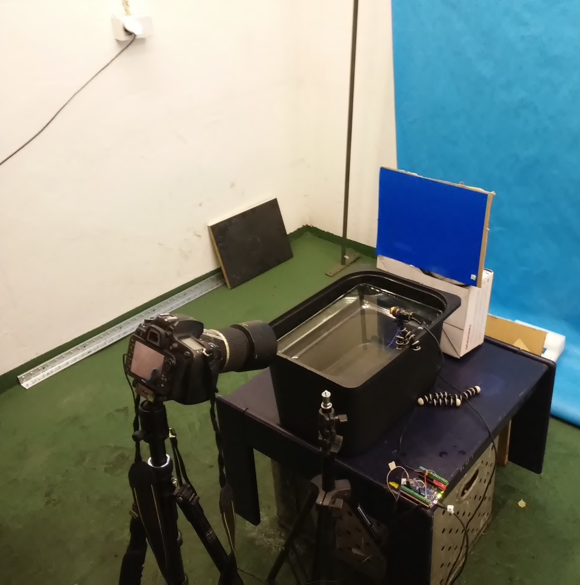
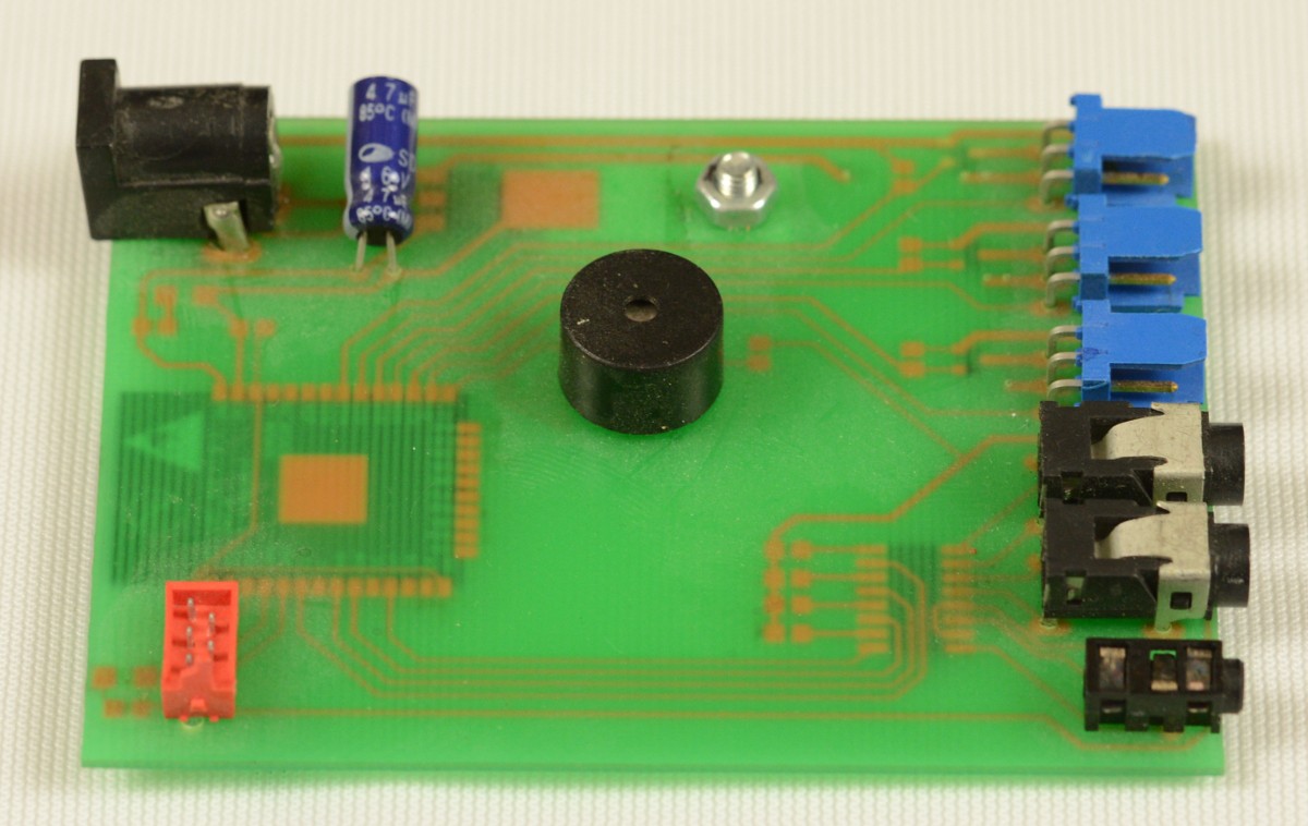
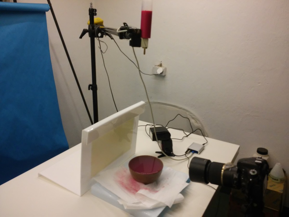
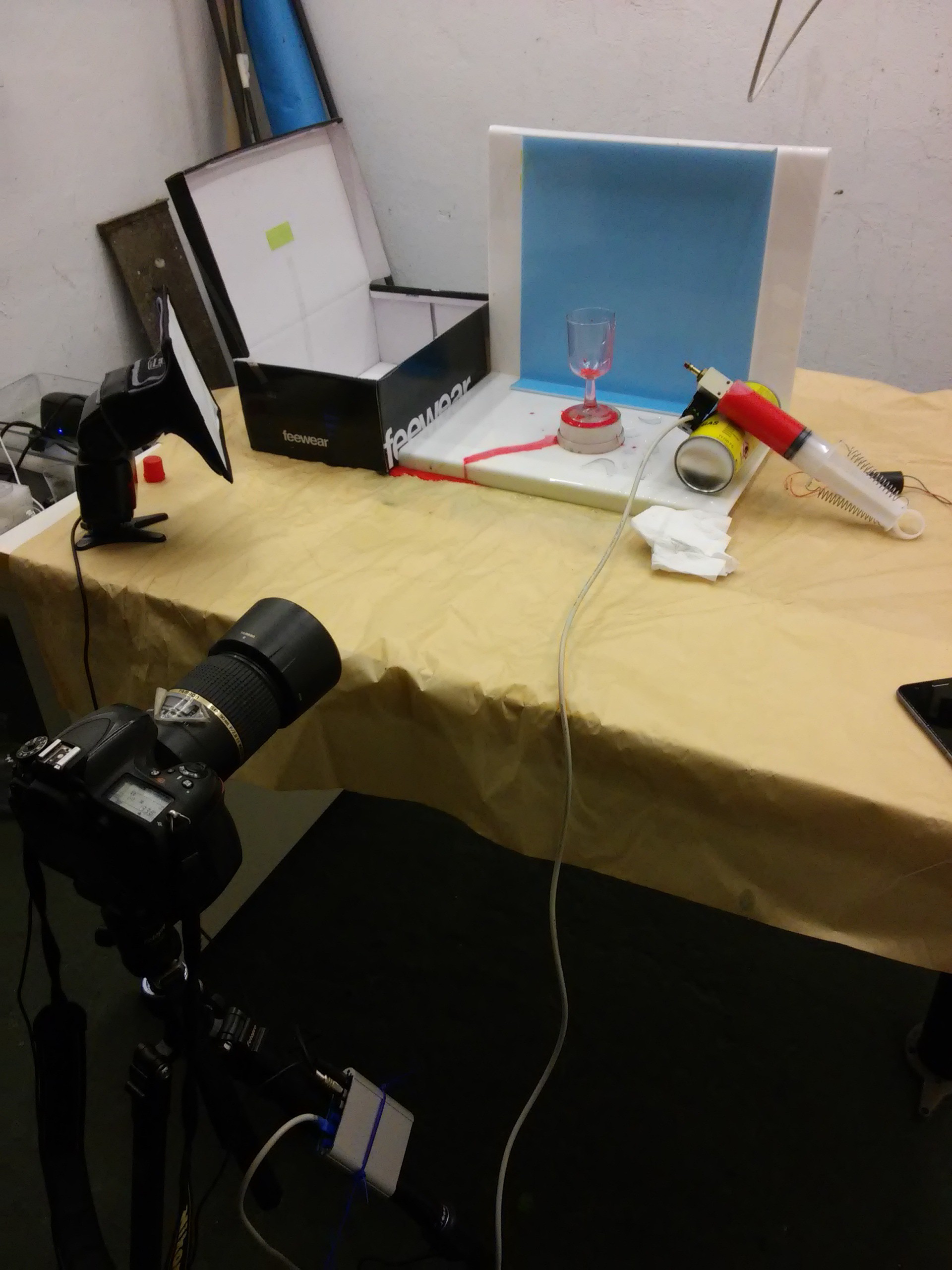
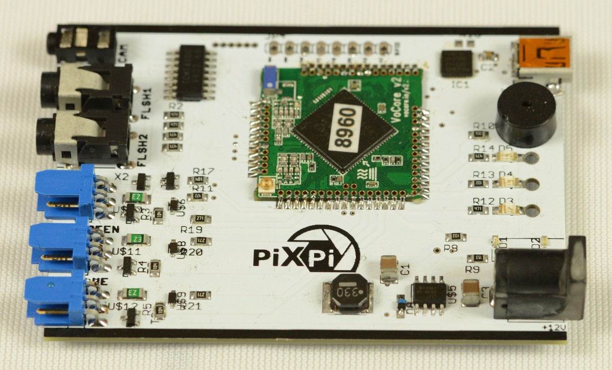
Approach 6: battle-proved
So on this board switching voltage regulator and some port protections was added and it worked really well, this board is fully functional and it's working until today. Also it was first board which was put in enclosure, with this I made most photos which you will see on website.
Conclusions:
-I don't really need led's for indication of flash and camera trigger state.
-It will be handy to not need for remove board from enclosure to connect to serial console of VoCore.
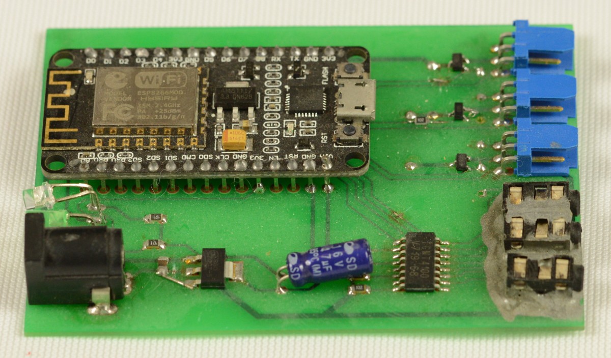
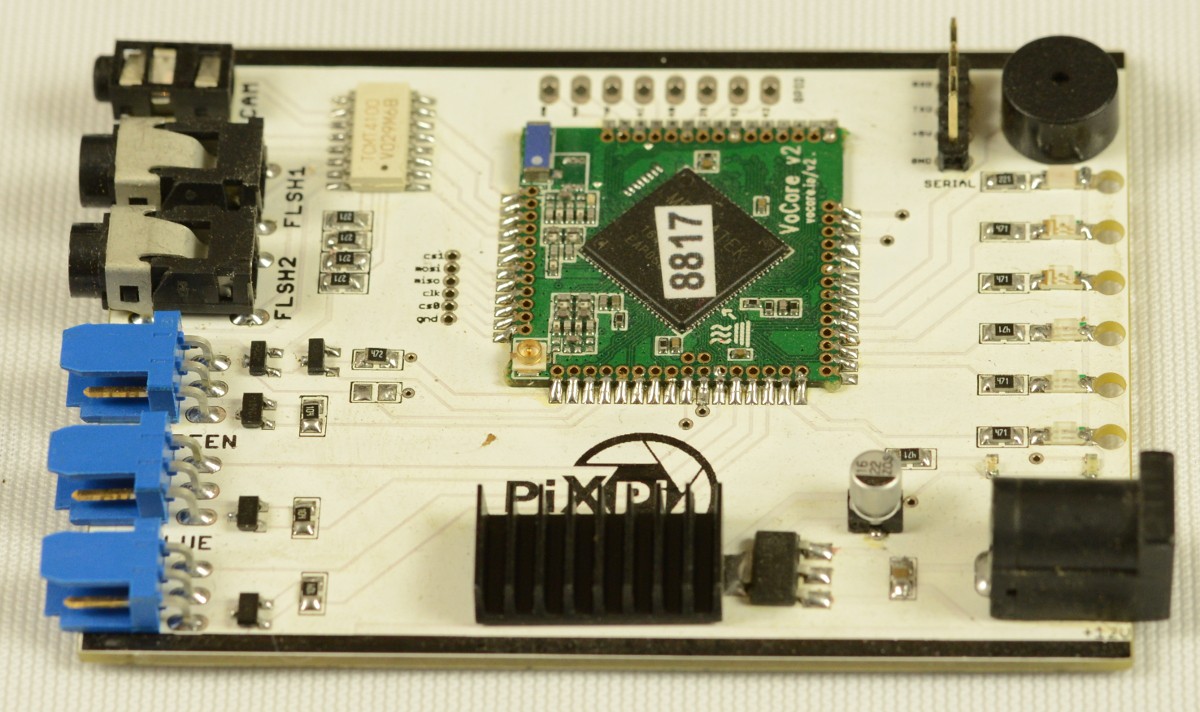
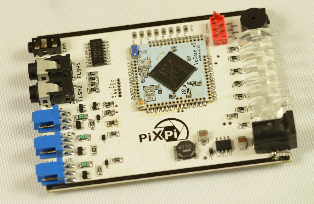
Approach 6: Current version
Aaand here we are, it's current version, as you can see 3 leds was removed and cp2102 usb/uart converter as well usb port was embedded on a board, so it's easy to access it.
Conclusions:
- Now i have doubts if one-wire is good choice for communication with motorised modules, but I not made a final decision of removing it as maybe it will be good to have it in future, now i'm exploring possibility of using "pulse/pwm"(just like in servos)mode for driving motorised modules.
- It's covering initial goals, so I focusing more on software and modules.
Ideas for future:
It would be very awesome to extend possibility of camera control with PiXpi, currently you can just release shutter, but in future I think it will be possible to control other parameters with ptp interface, through usb/ptp connection.
Discussions
Become a Hackaday.io Member
Create an account to leave a comment. Already have an account? Log In.