Close

Modules under the hood

A project log for PiXPi dslr camera controller

Modular and programmable DSLR camera trigger

krzysztof-krzeslakkrzysztof krzeslak 08/13/2019 at 18:500 Comments

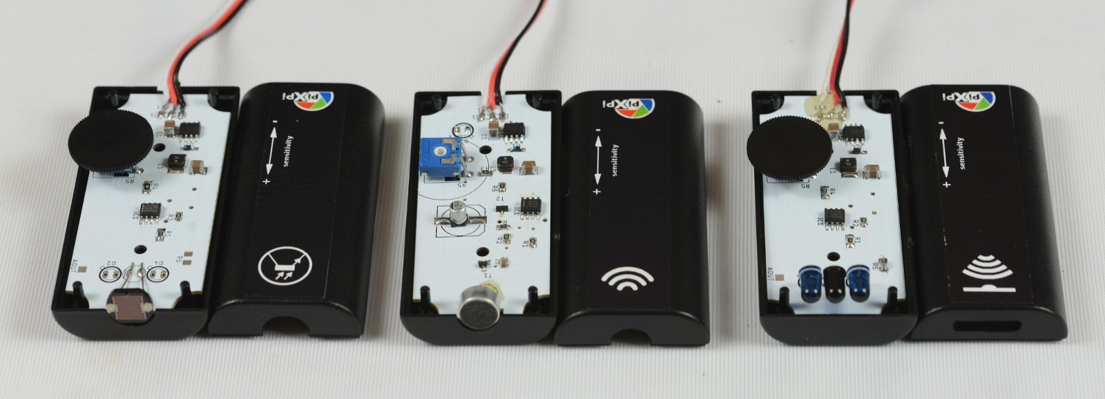
Hello, today i wanted share some detailed overview of modules, how they built and more importantly how they communicate with main controller, it's significant as standarized communication interface is something which make possible to easily extend capabilities through adding new module, so I put some thoughts behind design of modules interface.

So on controller there are 3 modules ports:

- Port red

- Port green 

- Port blue

Each port consist of 3 pins:

COMMON: configurable 3,3V input or output (additionally as 1-wire in case of port red)

12V supply(currently always on, but in future I plan to add "power drive" feature)

GND

                                                                       simplified port circuit
   Actual port driving circuit, there are some port's protections added and mosfet is actually driving low side

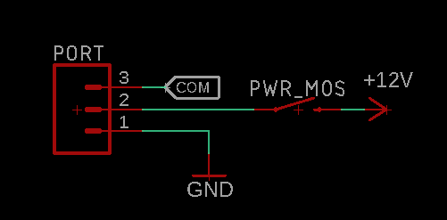
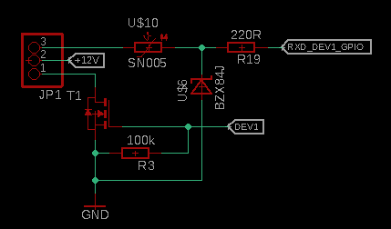
For driving Sensor modules following configuration of port will be used:

Com pin direction set to input, when sensor is not detecting anything it should give 3,3V after signal is detected it should pull COM pin to GND potential.

Supply for sensor is provided by two remaining ping - 12V and GND. 

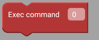
For driving Action modules

Com port set to output, when "action" is to be triggered, com port will go to High state out-putting 3.3V, but also reversed logic could be used here with no problems as default state can be configured as "HIGH" state.

For driving Motorised modules:

Currently I've implemented 1-wire communication(Over uart, so port red have additionally uart to 1-wire interface circuit)  for bi-directional communication over single pin with motorised modules, thought behind it was that 1-wire interface can serve multiple slaves, so using one port there will be be possible to communicate with multiple nodes, this could be useful for example for some multi axis sliders, but now I come to conclusions that maybe i over-killed it a bit and think about changing this approach to "servo-like" interface, so first I want to try driving motorised module using soft-pwm this will not have possibility of driving mutliple nodes with one port, but then not only port red will be capable to drive motorised module, but each of port, so still it should be fine, anyway I will keep uart/1-wire interface circuit on port red, as this can be useful in future, and interface circuit in quite simple. 

                                                       uart to 1wire circuit specific for port red,
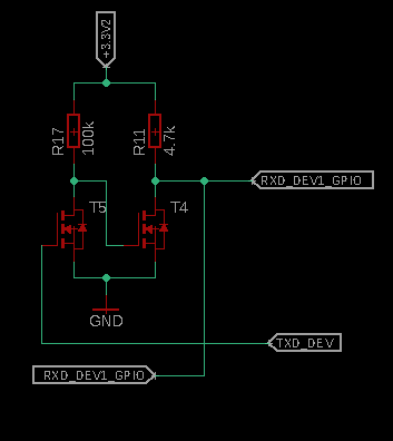
                        based on https://www.maximintegrated.com/en/app-notes/index.mvp/id/214

               Ports function are configurable from app, function refer to COMMON pin function:

(just note that "Com" is communication function of port, it's different thing from "Common" port)

In case of output's(port blue on this screen), default state can be configured, module selection is not used at all now, but thought behind adding it was to name port driving blocks with corresponding name's , for example not just "wait for port red", but "wait for noise" in case of selecting sound sensor on port red.


         After setting port(red in this case) to input mode, such blocks will be available in program editor

                                                         Available blocks in output mode
                                                                     Port red in "com" mode

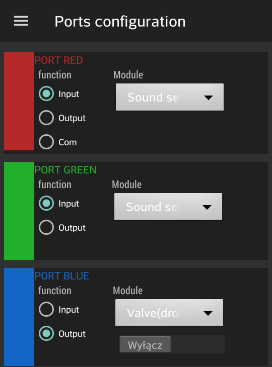
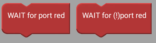
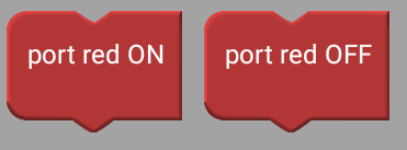
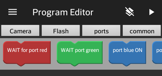
Reasoning behind naming port's with color's was that it's easy to distinguish quickly in program editor which port is being used.


                                               So what's under the hood of currently implemented module
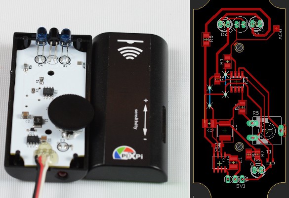
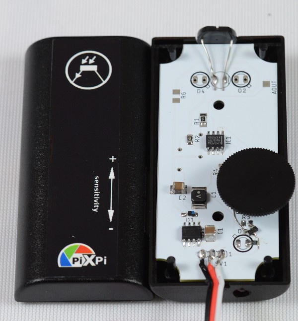
                            

                                                                                     reflection sensor

                                            Sources: https://github.com/krzysztofkrzeslak/pixpi-reflection-sensor

Reflection sensor consist of two iR-diodes and photo-transistor which is connected to voltage comparator, which compares voltage level set with potentiometer, it's supplied with AP1509 step-down converter. currently in best case operating range of this sensor is at maximum 35-40cm, but it differs greatly depending on color and surface of detected object, so in worst case for black material it can be reduced to 15cm, which is something which I want to improve in future. 


                                                                                                Sound sensor
                                                         Sources: https://github.com/krzysztofkrzeslak/pixpi-sound-sensor
                                     Sound sensor is based on ne555 chip, circuit is based on, just slightly modified to fit my needs:
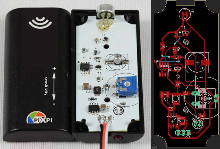
                                                                             https://www.doc-diy.net/photo/sound_trigger/


                                                                                         Light sensor

                                              Sources: https://github.com/krzysztofkrzeslak/pixpi-reflection-sensor

              Light sensor is...basically reused reflection sensor circuit without ir diodes as big photoresistor insted of phototransistor :)


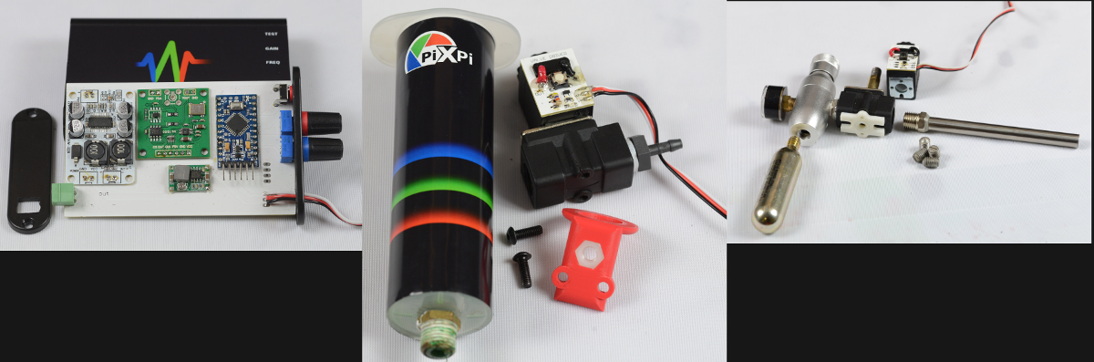
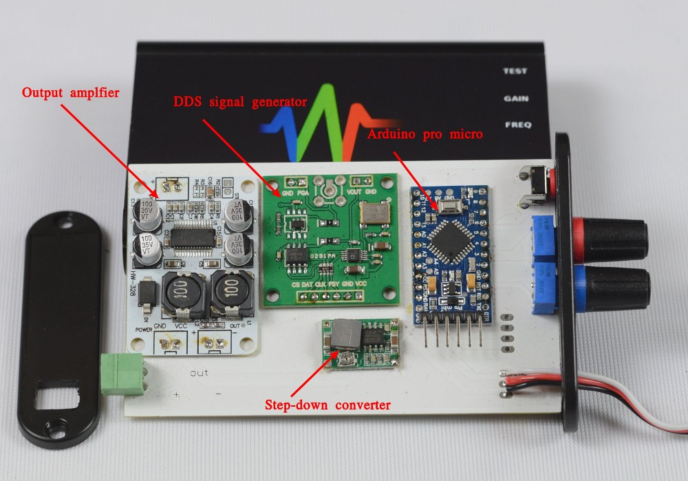
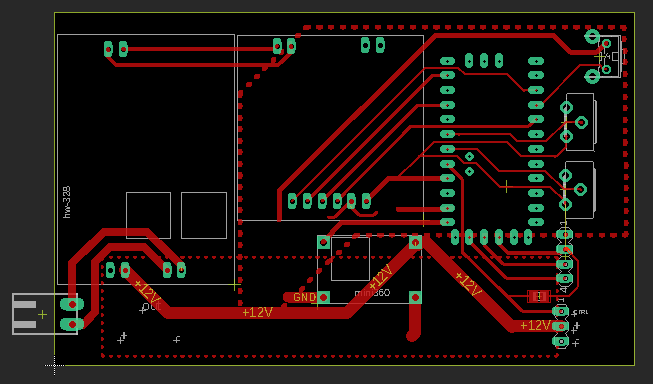
                                                                                              Speaker driver module
                                                              Sources:  https://github.com/krzysztofkrzeslak/pixpi-speaker-driver

For speaker driver I used Arduino, dds generator and power amp modules and i found it as a good decision as this reduced complexity and costs of circuit. All is enclosed in black anodised aluminium case from Hammond, bought from local electronics supplier, washers for potentiometers and button was 3-d printed. Operating principal is that when it receives "HIGH" signal on com pin, it's starting to generating signal with frequency and gain, set with potentiometers. btw. those un-routed traces are connected with polygon after applying it, yea this board also need some tweaks, as I need also change potentiometers on it as this which i used now are quite expensive.

                          
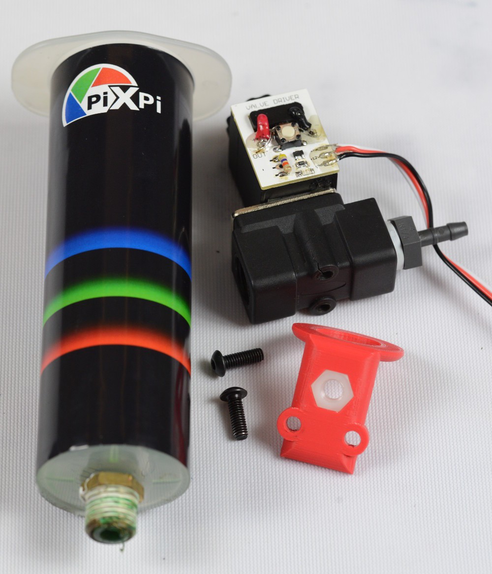
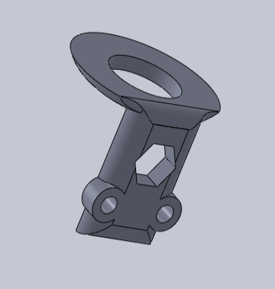
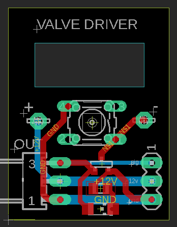
                                                                                               Pneumatic gun module
Heart of pneumatic gun module is solenoid valve, solenoid of this valve is driven through small board with mos-fet(more on this in droplet module description), also very significant part of this module is pressure regulator, which o get from Aliexpress, "proper" use for it is pressurising keg with beer but I must stick with bottled beer now ;), as it works pretty well as supply for pneumatic gun :p, it supply about 10 Bar's , which is just right for crashing bulbs and glass, but not too much to create some serious injuries to photographer, anyway still safety glasses are necessary ;)

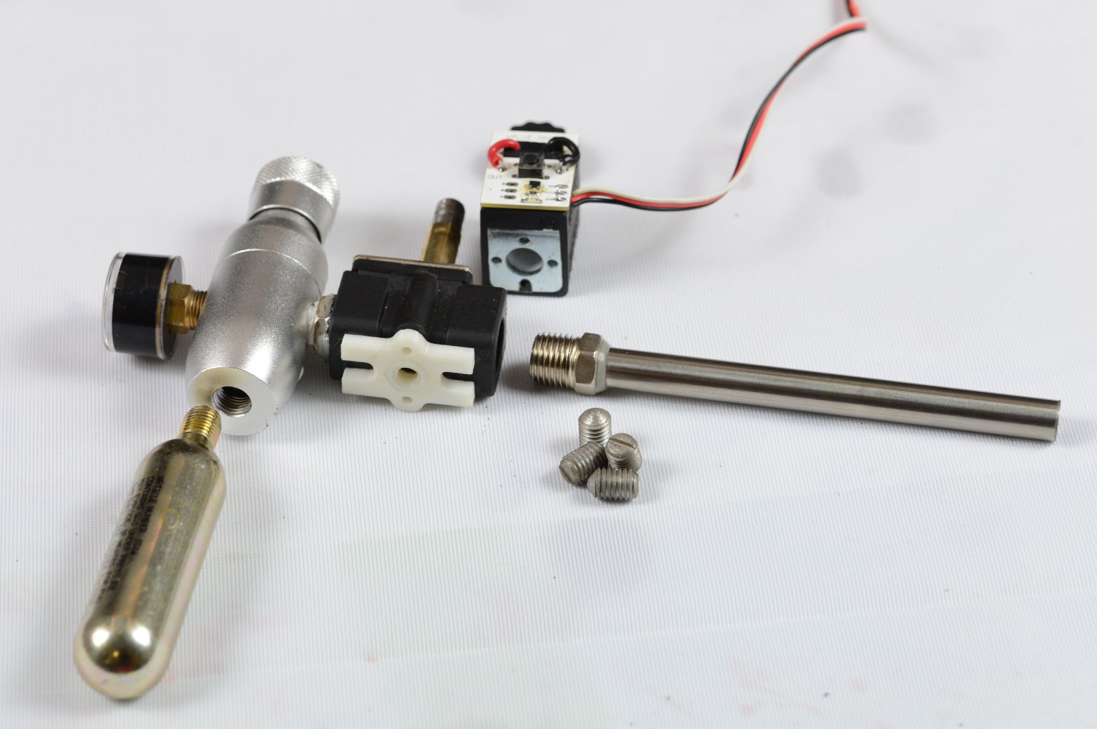
regulator: Aliexpress link, Here this regulators can be bought

valve: Aliexpress link   , those are marketed as fish tank valve ;)

For bullets i use something which is called clamping screw, which i get at local hardware store, they are cheap, working very well and even looks like bullets: google search link

barrel is just piece of stainless 10mm pipe, glued with to threaded reduction piece.

                                                                                          Droplet module:

                                     Solenoid driver source:  https://github.com/krzysztofkrzeslak/pixpi-solenoid-driver

For droplet module as liquid reservoir syringe cylinder was used I just put sticker to it to make it look nice, valve unit is same as for pneumatic gun, so solenoid driven with mosfet board, also on mosfet board button can be seen, it's for manual valve opening, in case of this module it's very handy for example for filling valve with liquid, tripod mount is 3d printed.

                                                                                                  Valve "holder" design
Valve driver board, here also some tweaks will be needed I need to add mos-fet gate protection and maybe not to drive coil directly through tact switch, but with using of on-board mos-fet.


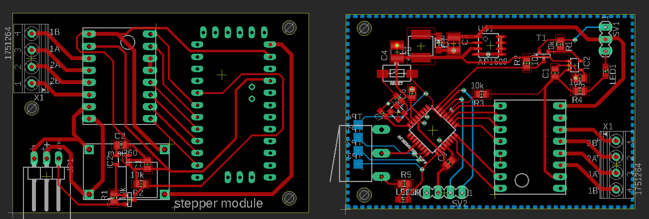
                                                                                                Motorised modules (ExtremeMacroRIg)
                                          Currently one motorised module which is built is macro rig, currently i'm working on driving circuit

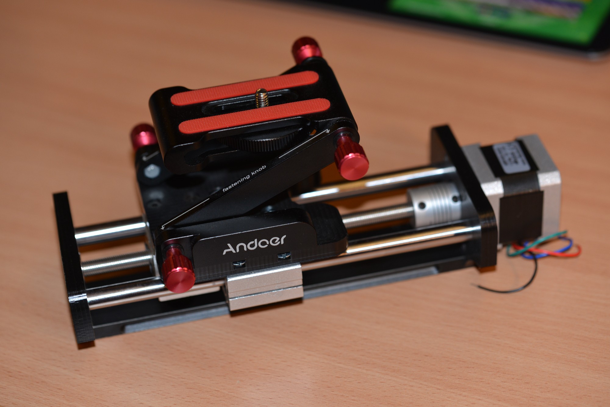
                                                         Sources:  https://github.com/krzysztofkrzeslak/pixpi-stepper-driver
Currently I've got 2 prototypes for driving boards,but unfortunately I've got some problems making newer board working, so for software development I will fallback to older board, as generally they should be software compatible as i'm planning to put arduino bootloader to second board


...so for today I will end on this, just follow for updates ;)

Discussions