Close
0%
0%

Lab Bench III

You guessed it! It's a lab bench & my third. The kicker? It's unlike any other...

Similar projects worth following
A lab bench is a very personal thing. You spend a lot of time working at it and, by impacting what types of tools and processes you have space for, it fundamentally shapes how you work. As a student, I've been very nomadic for the past few years and have had to move all of my equipment with me. This has mandated that I use a flimsy "bench" which folds in two and has rickety homemade shelves which are easily disassembled. With steadier housing on the horizon, I've decided to retire my trusty portable setup for something a little better. The bench I'm building is designed to be sturdy more than portable. It will also have shelves built directly onto the surface which are specifically designed to accommodate my test equipment in a 'form fitting' way :) . It will be broad enough to comfortably fit large electronics projects while also holding an A5 notebook and 15" laptop. Plus, a plethora of electronic devices will be integrated into the bench makin

Here are the key parameters I want in this bench:

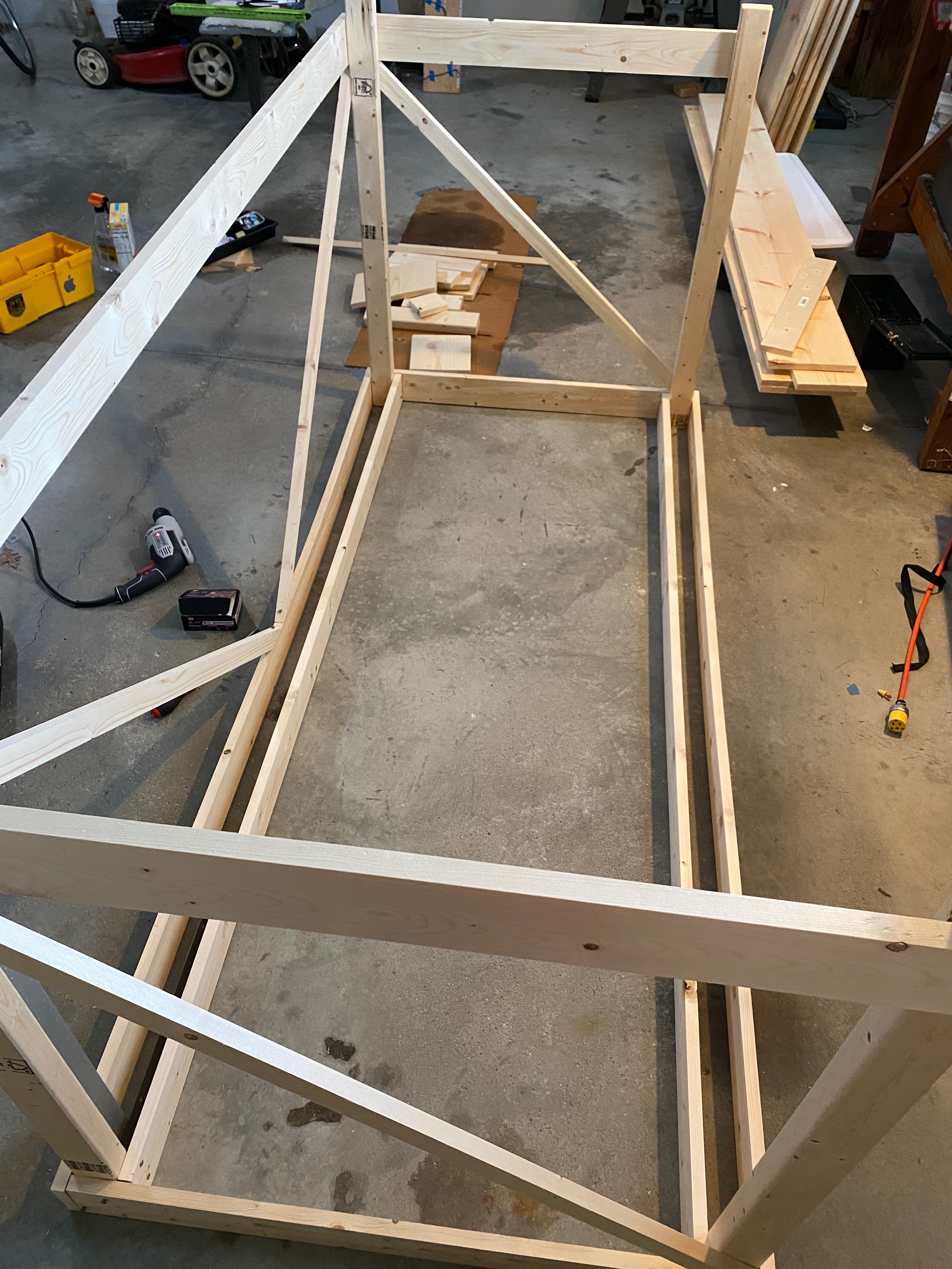
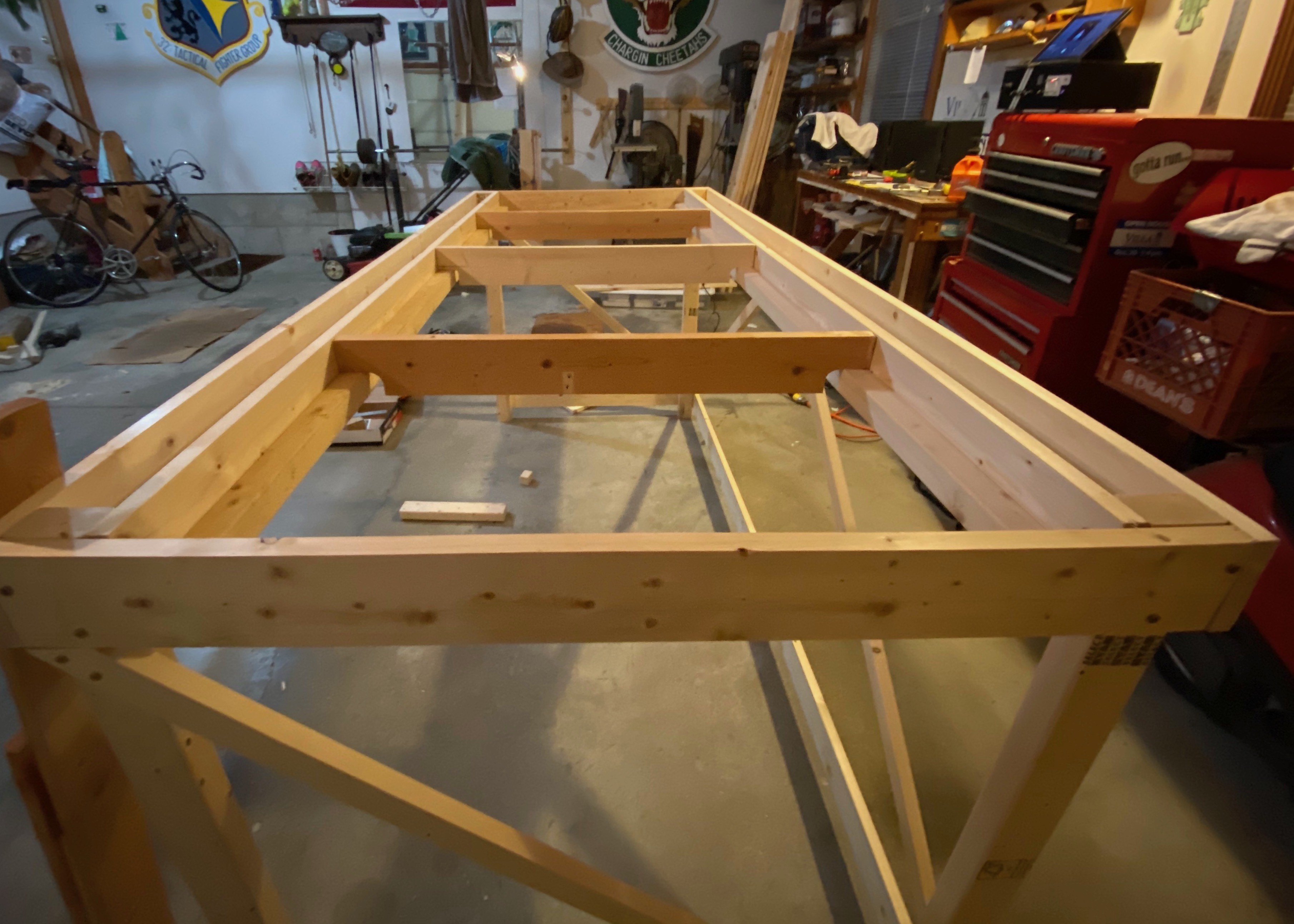
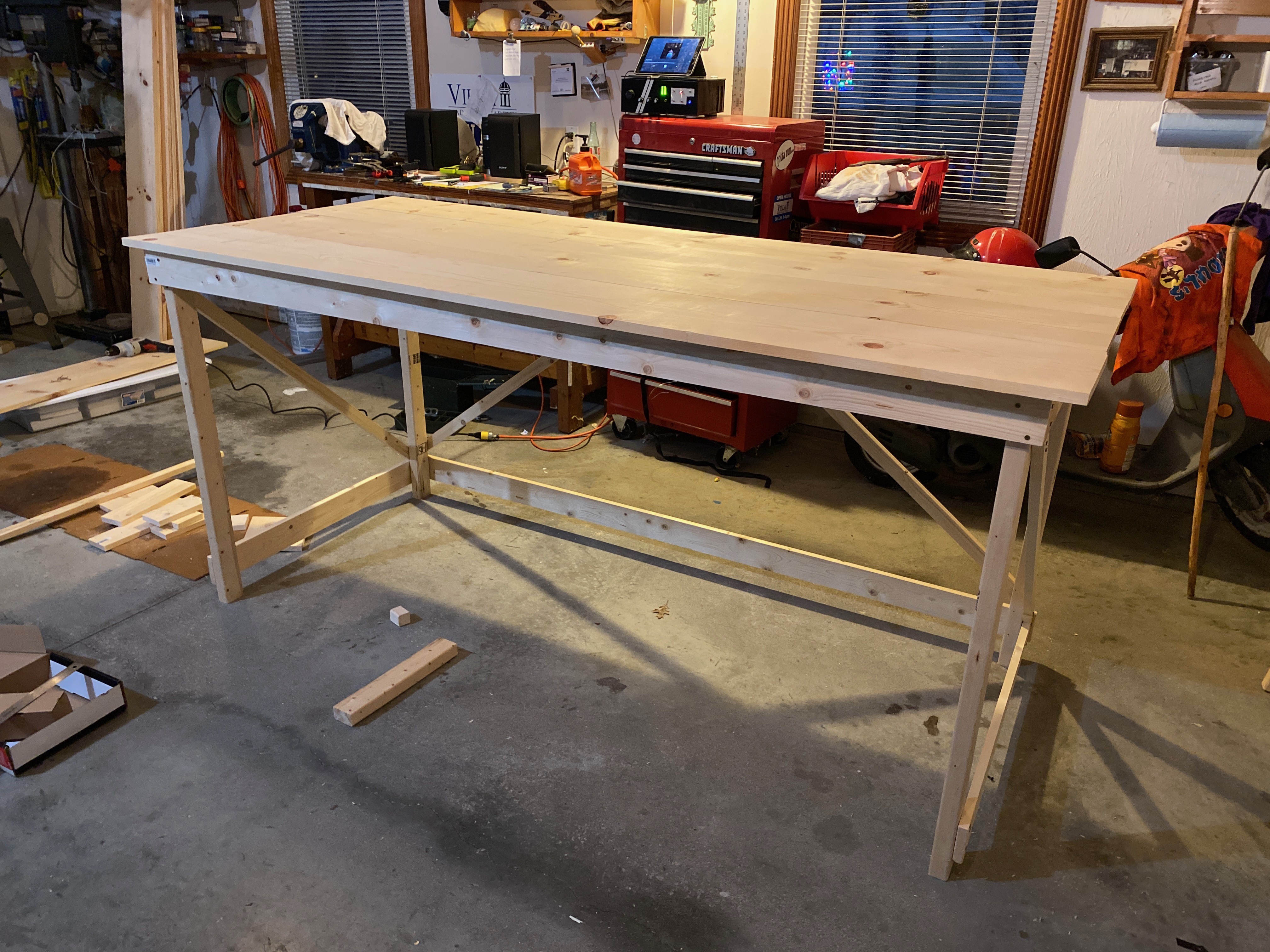
  • Sturdy: It needs to be strong
  • Big: I want to have room for my stuff.
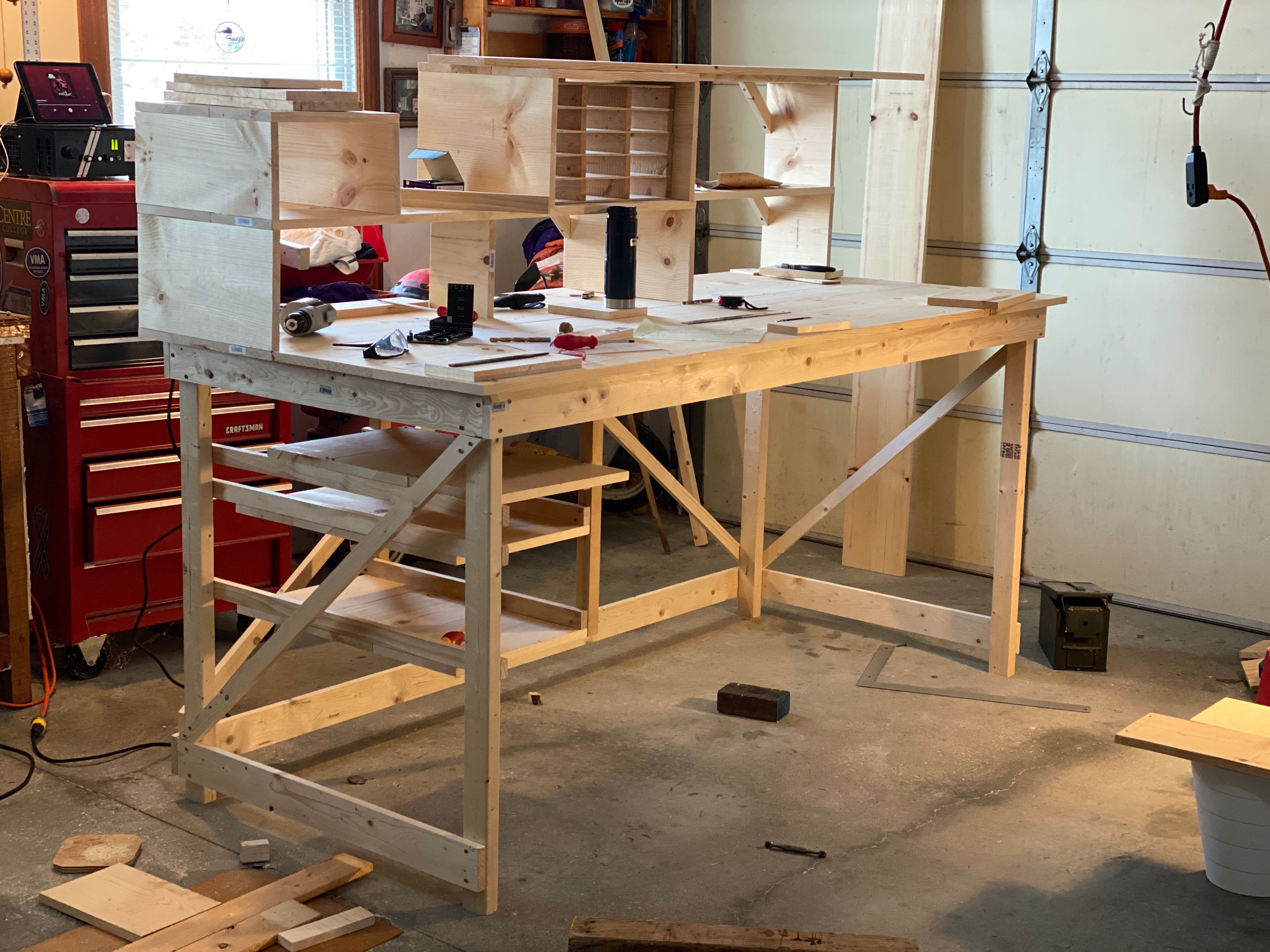
  • Good shelves:
    • Form fitting: Make room for things like my scope, AWG, and chunky PSU but don't waste space!
    • Lots of space for hand tools
    • Component rack: Store 15+ boxes housing various sorted components
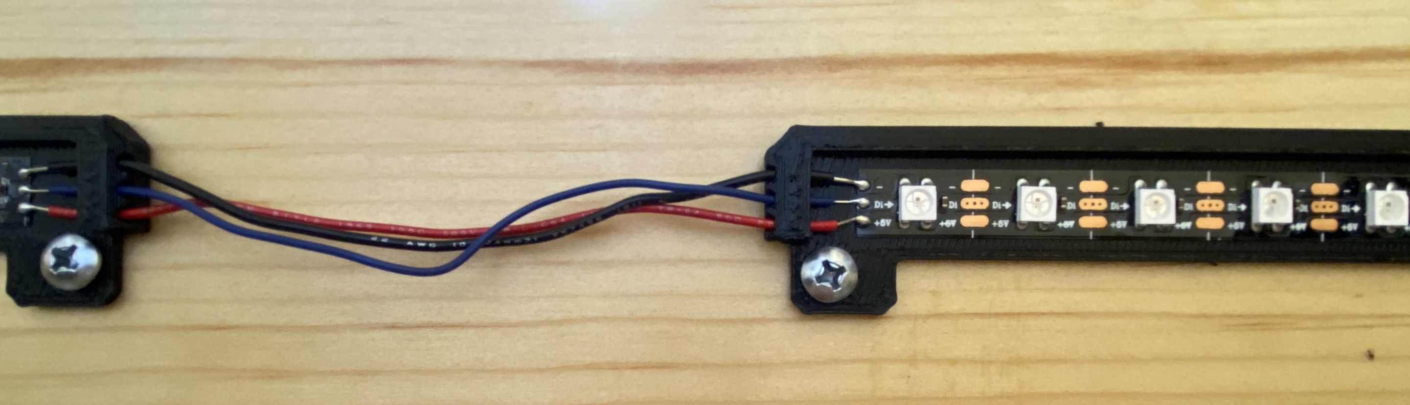
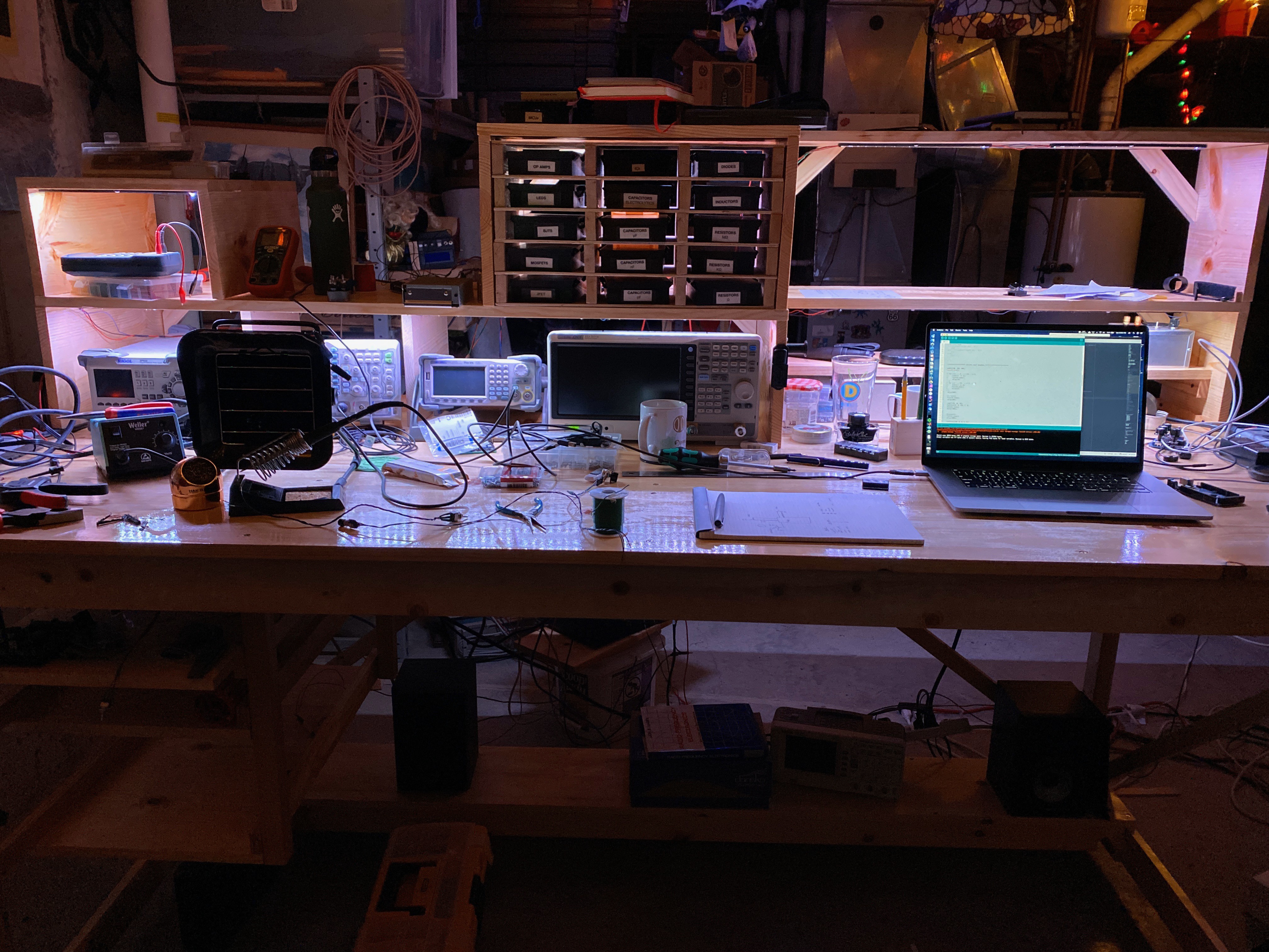
    • Lights: I installed LEDs on my current bench - I want the same (or better - stay tuned...) here.
  • Integrated Electronics:
    • Lights: I already talked about this
    • 12V DC bus: I build a lot of smaller devices which run on 12 V. Keeping a ton of wall warts around is a pain. Plus most of the cheap ones seem to use really crappy SMPS which are quite noisy. Having one big beefy 12V supply lets me ditch these for a better one & cut down on some wires.
    • Equalizer: I'm often either listening to music or building audio electronics. Installing one of the equalizers I've already built makes sense.
    • Flood lights?: I drop tiny parts all the time. Putting some flood lights on the bottom to light up the floor when needed could help.
    • Thermometer/hygrometer + data logger: Okay I can't justify this one. But why not
  • Tool mounts: On my previous benches I 3D printed some structures to mount specific wires, tools, etc. I use them daily and plan to make more for my new bench.

  • Building the Shelf Lights

    Grant Giesbrecht01/14/2020 at 19:31 0 comments

    I put LEDs on the underside of my shelves for my old bench and really liked the extra illumination - plus it looked cool. I'm doing the same thing for this new bench, but I'm using individually addressable LEDs and a better light mounting system. 

    I'm using WS2812B LEDs and I'm controlling them with an Arduino Mega. I didn't want to use the adhesive that comes with the LEDs directly on my shelves because the adhesive is kinda crappy. Instead, I'll use their crappy adhesive on 3D printed mounts which will screw into my shelves. If the adhesive fails, I can experiment with other glues without worrying about damaging the finish of my shelves. More importantly, the 3D printed light mounts will also provide some rigidity to the wires, which from prior experience, really want to tear their pads off the light strip. They'll also provide a shade which hides the bright emitters for a more polished and tidy look.

    Here's a joint between two light bars. The ends have guide-holes for the wires, helping protect the fragile connections.
    Make sure you don't connect your data wire to the data out side rather than the data in side. I had to run a wire along the edge to connect to the right pin after screwing this up. Cyanoacrylate-based superglue works well for adhering the wire to the 3D printed bar.
    I used dupont connectors to connect my light bars to the control signal and power.
    The control electronics were a lot easier than I expected. I was thinking I'd need to make a PWM driver circuit like I did for my previous lab bench light build. However, because the LEDs are individually controlled, the intensity variation is performed locally within each LED, making my job super simple. I wire my beefy 100W, 5V 20A power supply to the power connection, then connect the data lines to any digital pin on the Arduino. Cool!
    I have 10 light bars, each holding 16 LEDs distributed throughout five shelf-nooks. I even have one behind my black component boxes for some cool backlighting.

    The rest is programming. In order to make it easy to make cool patterns, I estimated the relative position of the light bars and made function which understands my lights to be arranged in a grid 96 columns wide and two rows high. I can assign any color to any 'pixel' on my shelves and the function automatically locates the correct bar and turns on the LED(s). Because of the arrangement of the bars and the spacing between them, there isn't a 1-to-1 association between LEDs and grid squares. For example, the light bar behind my centrally located grid-shaped shelf holding black boxes has 16 LEDs but occupies 14 cells in my grid. Now I can make cool animations below without having to worry about the relative position of different bars, I just assign colors to pixel locations like on a screen, but the screen is actually a shelf :)

  • The Build

    Grant Giesbrecht12/22/2019 at 22:40 0 comments

    I'm building the actual wooden bench. I'm not going to go into much detail on this part of the build, however the one really important tip I've got for anyone building a bench is to use diagonal beams, especially for the verticals components. It's crazy how much more rigid this will make your bench and how few DIY benches online use them. I swear if you use boards half the size you were planning but add diagonal braces, your bench will be way more rigid than if you try to overbuild your bench with huge beams but no cross-bracing. Pre-drilling your screw holes makes life way better, and ofc don't screw into the end grain! If you want more details on my exact build strategy or diagrams, leave a message in the comments and I'd be happy to help. 

    The sizes of boards I used are:

    • 2x3s for the legs
    • 1x4s for the horizontals
    • 1x2s for the diagonals
    • 1x8s, 1x10s, & 1x12s for the surface boards

    Some other specs:

    • Height: 1,05 m
    • Length: 2,25 m

    Here are some photos showing my general strategy. The idea was to use four 1x4s as horizontal beams supporting the table surface, then lay 3 across in the perpendicular direction to keep the middle from sagging and to keep all the boards aligned. Everything screws into either the legs, or the ring of 1x4s (which also screw into the legs) around the top and base of the table.

    I installed the legs upside down because it made it easier to keep everything square.
    The supports in the middle rest on two 2x2s I screwed to the 1x4s. This is a lot stronger than using some type of bracket.
    The bottom shelf uses the same idea as the top surface - surface screws into a 1x4 that rests on a 2x2.
    The side shelf uses two 2x2s that drop down from one of the horizontal 1x4s to mount 1x2s. The 1x2s will mount the planks making up the surface of the shelf (not pictured).
    The completed bench, before adding shelves etc
    The surface shelves are broken into four parts. Here all four are mounted on the bench.

  • EDL Hardware Working

    Grant Giesbrecht09/14/2019 at 07:37 0 comments

    I got new parts from Mouser and finished populating my boards. First power up didn't work completely: 1.) the LEDs blinked so fast they looked like they were always on and 2.) most of the time the display wouldn't turn on at all and I'd have to restart the machine. I found out the problems were caused by 1.) no delay in my pattern display demo program so the characters cycled so quickly, every segment looked like it was on. 2.) I soldered the wrong timing components for the initial condition setting circuit. Instead of 10kΩ and 22nF I needed 100kΩ and 100nF. I used these correct values during my breadboard test - I'm not sure why I put the wrong values in the schematic ¯\_(ツ)_/¯. These simple fixes got it up and working nicely.


    I updated the firmware on the Arduino to read out data from the sensors and show it on the display assembly. I noticed that I flipped the enable wires for the 1st and 3rd characters but is fixed very easily in software. Temperature (C), relative humidity (%), and pressure (kPa) are displayed.

  • Building the EDL

    Grant Giesbrecht09/03/2019 at 05:42 0 comments

    The boards arrived, however I only got them partially assembled because I ran out of solder ( oops). That's why a lot of components haven't been populated yet. However everything required to test the critical systems was populated. I couldn't get it to work - I traced the issue down to the ring counter. Probing the inputs to U3 showed that it was being fed the correct signals. It looks like U3 is a goner. I'm going to replace it, but can't until I get a new shipment from Mouser - it turns out that was my last x174.

    This is where I connected all three boards (control board + shift register board + display breakout). The breadboard is just being used to link the 8 Male-Female jumpers connecting the control and shift register boards.

  • EDL PCBs (Part 1)

    Grant Giesbrecht08/10/2019 at 01:41 0 comments

    I soldered an Arduino Nano onto a piece of protoboard to wire it up to all the peripherals.

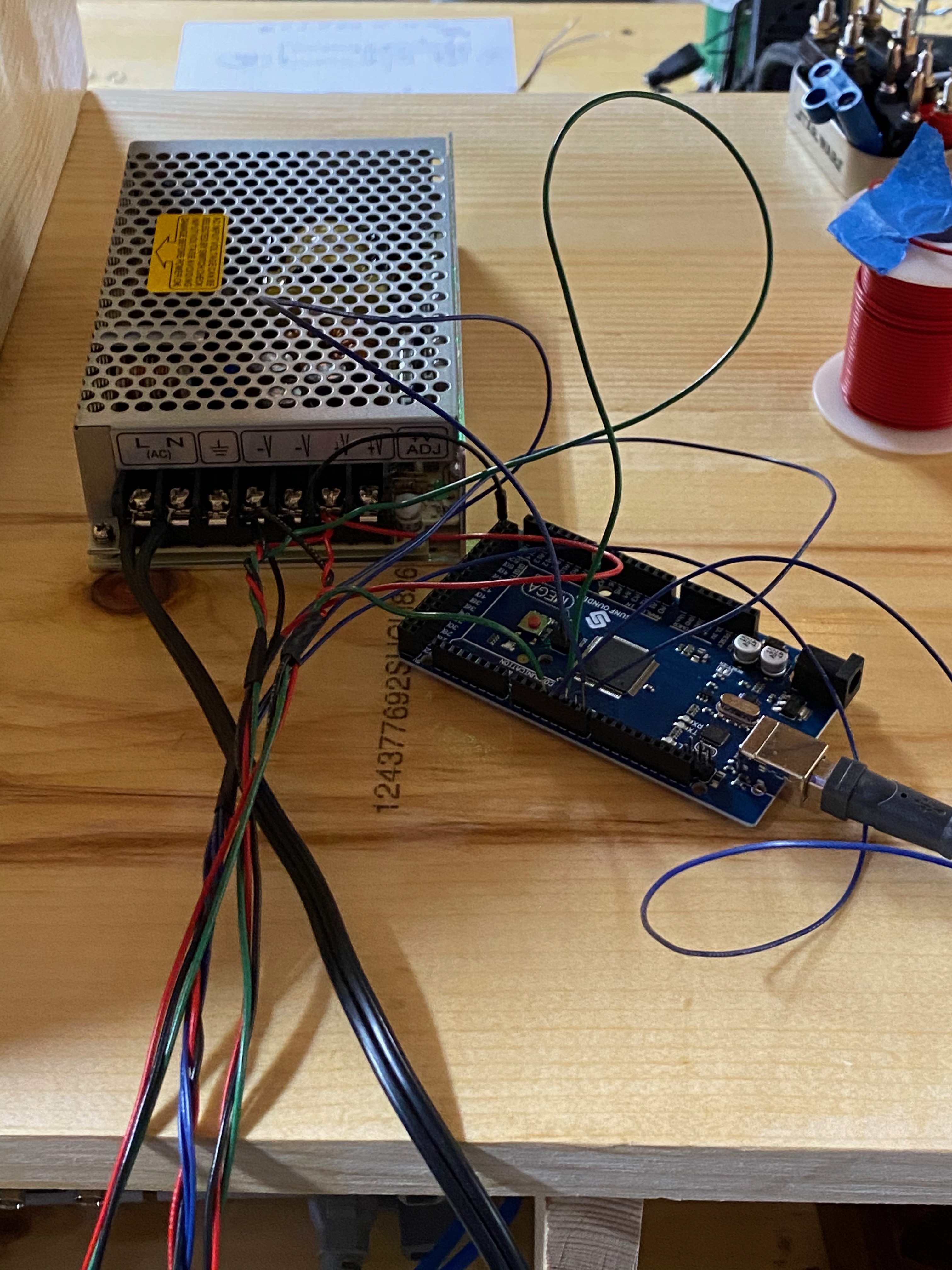
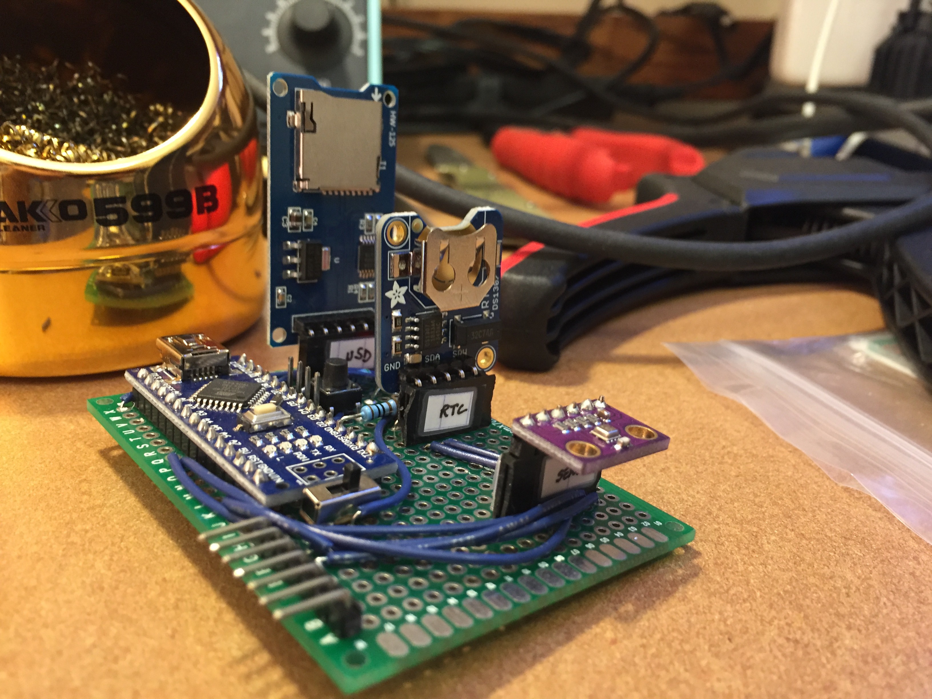
    This board also has the real-time clock, MicroSD card module, the sensor, a push button (w/ debouncing circuitry) for cycling through error codes on the display, a switch to disconnect Arduino power, and a power LED for the Arduino.

    I've designed PCBs for the display breakout and display drivers too.
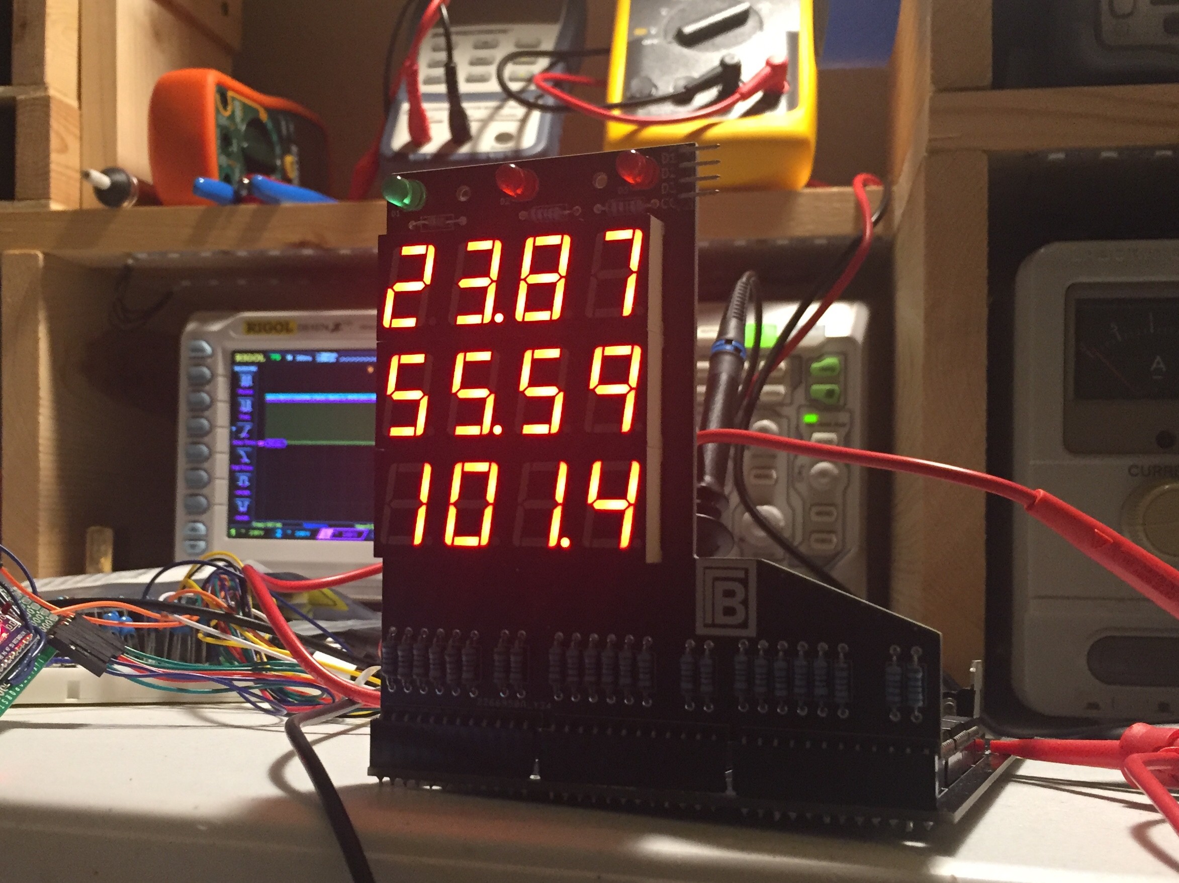
    I wrote an Arduino sketch which you can find on the project's GitHub repo. Because I don't have the display driver board yet it's still a work in progress, but it can read the sensor values, log them on the SD card, and report them to the serial monitor.
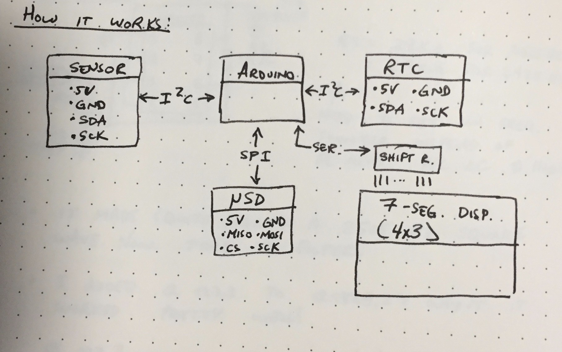
  • Electronics I - Environmentals Display & Logger

    Grant Giesbrecht07/31/2019 at 08:14 0 comments

    The environmentals display and logger (EDL) displays the temperature, humidity, pressure and time, then logs the data in a microSD card. I'm using an Arduino as the brains of the operation. I bought  a COTS SD card module, thermometer/hygrometer/barometer module, real time clock (RTC), and LCD display. Later I decided to switch the LCD display to 7 segments because I like the look better (especially against natural wood). The switch to 7 segment displays severely increased the complexity of the system because instead of the prepackaged solution of the LCD I needed to implement a system to control all 96 LEDs for the displays (96 = (7 segments + decimal point) * 4 characters per display * 3 displays ). I opted to use shift registers and charlieplexed 7 segment displays because it would let me control all 96 lights with only four wires. This is a pretty commonly used system, but here's a quick run through of the idea:

    • Load data in 12 8-bit shift registers. Each register stores bits to control one 7 segment display (plus decimal point).
    • Turn one character on in each 4-character display at a time (the display's only let you activate one character at a time to reduce the number of pins) - ie. turn on 3 characters total at a time. 
      • A ring counter (run by a ~500 Hz clock) turns exactly one character's shift register's outputs on for each display, then shifts to next, and so forth.

    These diagrams taken from my notebook show the general idea:

    I decided it was complex enough to warrant a custom PCB - I don't want to all 200+ connections by hand! First though I tested all of the major subsystems on a breadboard so I wouldn't miss any huge problems when I ship my design out to a boardhouse. First I built the clock. I opted for a super simple timer 555 circuit.

    It worked quite nicely. Next I went for the ring counter. You can use a couple discrete D-type flip flops to make a one-hot ring counter (ie. one with only output on a time - we need this so we don't turn on two characters at once and short the outputs of two 74HC595 shift registers to each other). The problem here is that you need to guarantee an initial condition in which exactly one flip flop is set high and all other are low. I wasn't able to find a suggestion for how to do this on the web so I came up with this solution:

    The idea is to use a 74HC244 line driver to set the initial conditions correctly whenever the Arduino brings the blackout line low (this signal is also connected to the flip flops and disable's their output, thus allowing the Arduino to turn off the displays, hence the name). An RC network is used to add a delay between the Arduino bringing blackout high and the initial condition register turning off. This guarantees a few clock cycles occur while the flip flops are enabled and the initial conditions are still held. This worked nicely also. Next I set up the shift registers and wrote an Arduino program to load data into them. I ran into some software bugs and mistakes in my wiring (one of which shorted the shift register outputs and fried a few chips - oops). I worked out all the kinks though and got the displays to show what I wanted. The only catch was that the amount of current drawn by the display from the ring counter was too much, contrary to what my back of the envelope calculations predicted. Adding a P-channel MOSFET to drive the common anodes of the display fixed this. Not shown here is a 74HC04 hex NOT gate used to invert the signal from the ring counter - the 74HC595s use active-low output enables, so do the PMOS transistors.

    Here's the beast set up on a breadboard displaying demo data from the Arduino. I programmed the Arduino to display a series of characters and patterns to verify everything was working perfectly. I also only hooked up two characters to save some breadboard complexity. 

View all 6 project logs

Enjoy this project?

Share

Discussions

Similar Projects

Does this project spark your interest?

Become a member to follow this project and never miss any updates