 Grant Giesbrecht
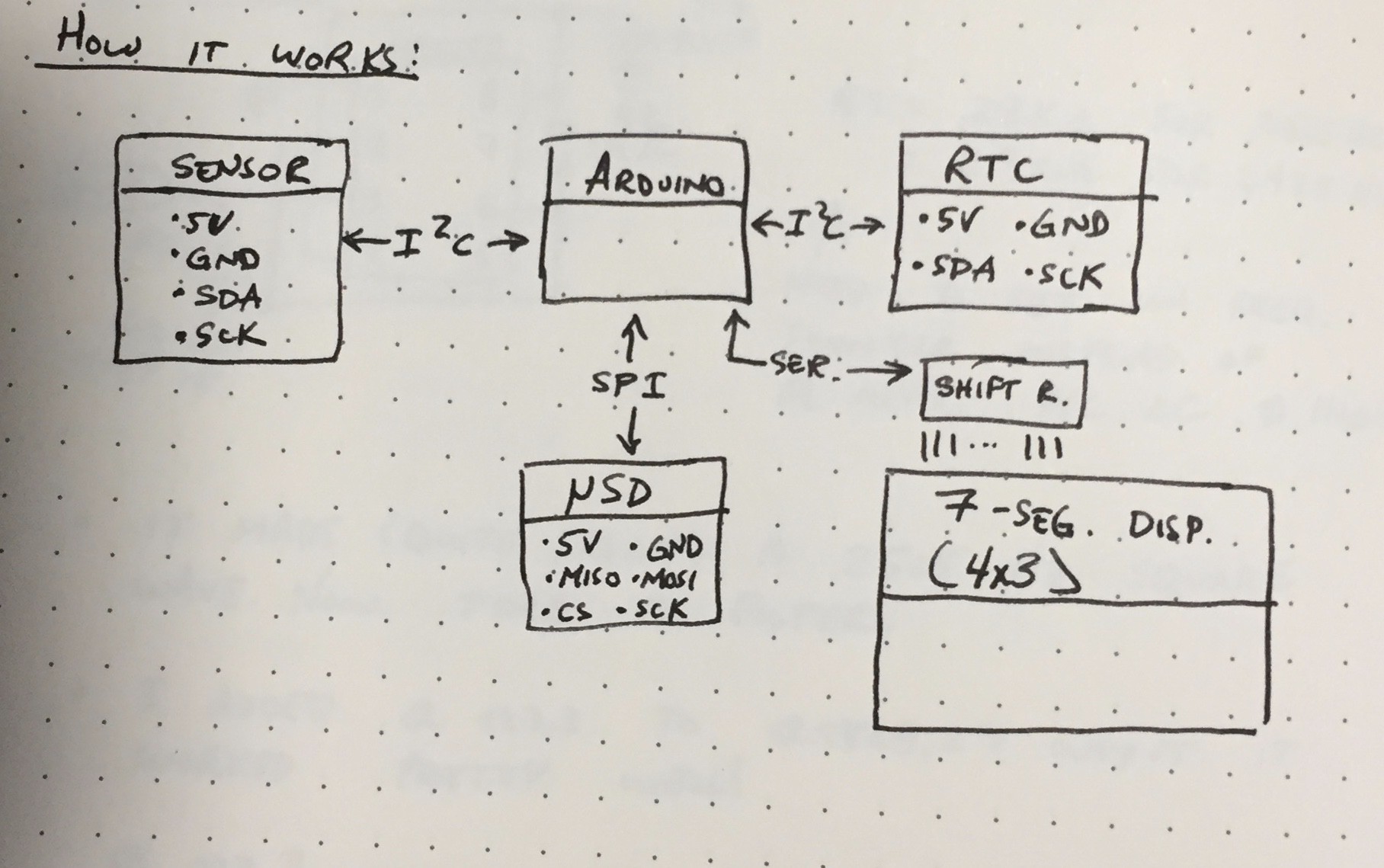
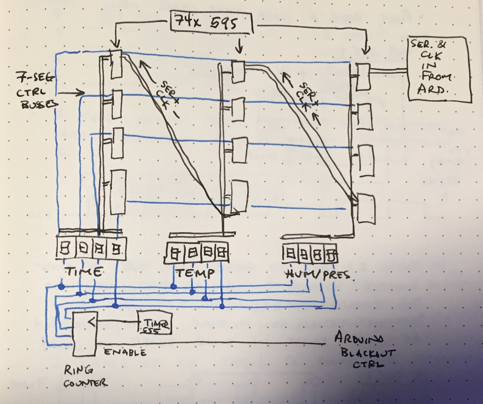
The environmentals display and logger (EDL) displays the temperature, humidity, pressure and time, then logs the data in a microSD card. I'm using an Arduino as the brains of the operation. I bought a COTS SD card module, thermometer/hygrometer/barometer module, real time clock (RTC), and LCD display. Later I decided to switch the LCD display to 7 segments because I like the look better (especially against natural wood). The switch to 7 segment displays severely increased the complexity of the system because instead of the prepackaged solution of the LCD I needed to implement a system to control all 96 LEDs for the displays (96 = (7 segments + decimal point) * 4 characters per display * 3 displays ). I opted to use shift registers and charlieplexed 7 segment displays because it would let me control all 96 lights with only four wires. This is a pretty commonly used system, but here's a quick run through of the idea:
- Load data in 12 8-bit shift registers. Each register stores bits to control one 7 segment display (plus decimal point).
- Turn one character on in each 4-character display at a time (the display's only let you activate one character at a time to reduce the number of pins) - ie. turn on 3 characters total at a time.
- A ring counter (run by a ~500 Hz clock) turns exactly one character's shift register's outputs on for each display, then shifts to next, and so forth.
These diagrams taken from my notebook show the general idea:
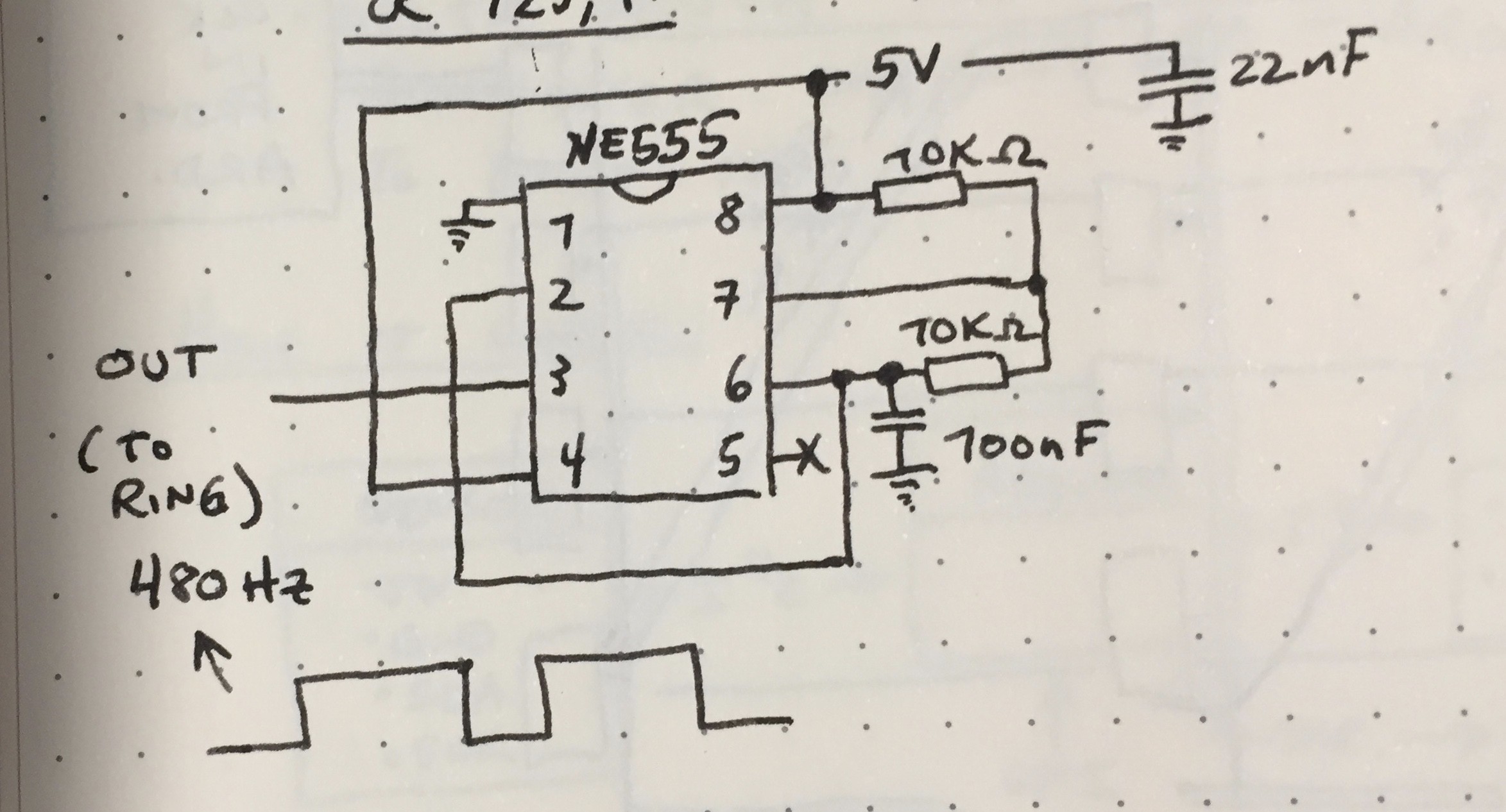
I decided it was complex enough to warrant a custom PCB - I don't want to all 200+ connections by hand! First though I tested all of the major subsystems on a breadboard so I wouldn't miss any huge problems when I ship my design out to a boardhouse. First I built the clock. I opted for a super simple timer 555 circuit.
It worked quite nicely. Next I went for the ring counter. You can use a couple discrete D-type flip flops to make a one-hot ring counter (ie. one with only output on a time - we need this so we don't turn on two characters at once and short the outputs of two 74HC595 shift registers to each other). The problem here is that you need to guarantee an initial condition in which exactly one flip flop is set high and all other are low. I wasn't able to find a suggestion for how to do this on the web so I came up with this solution:
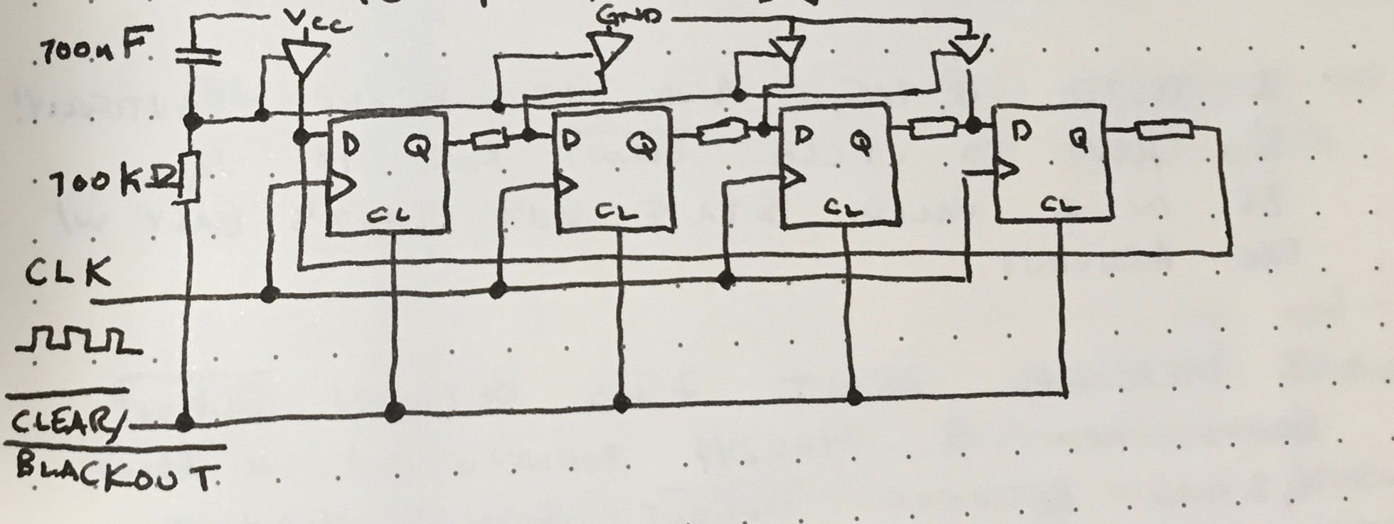
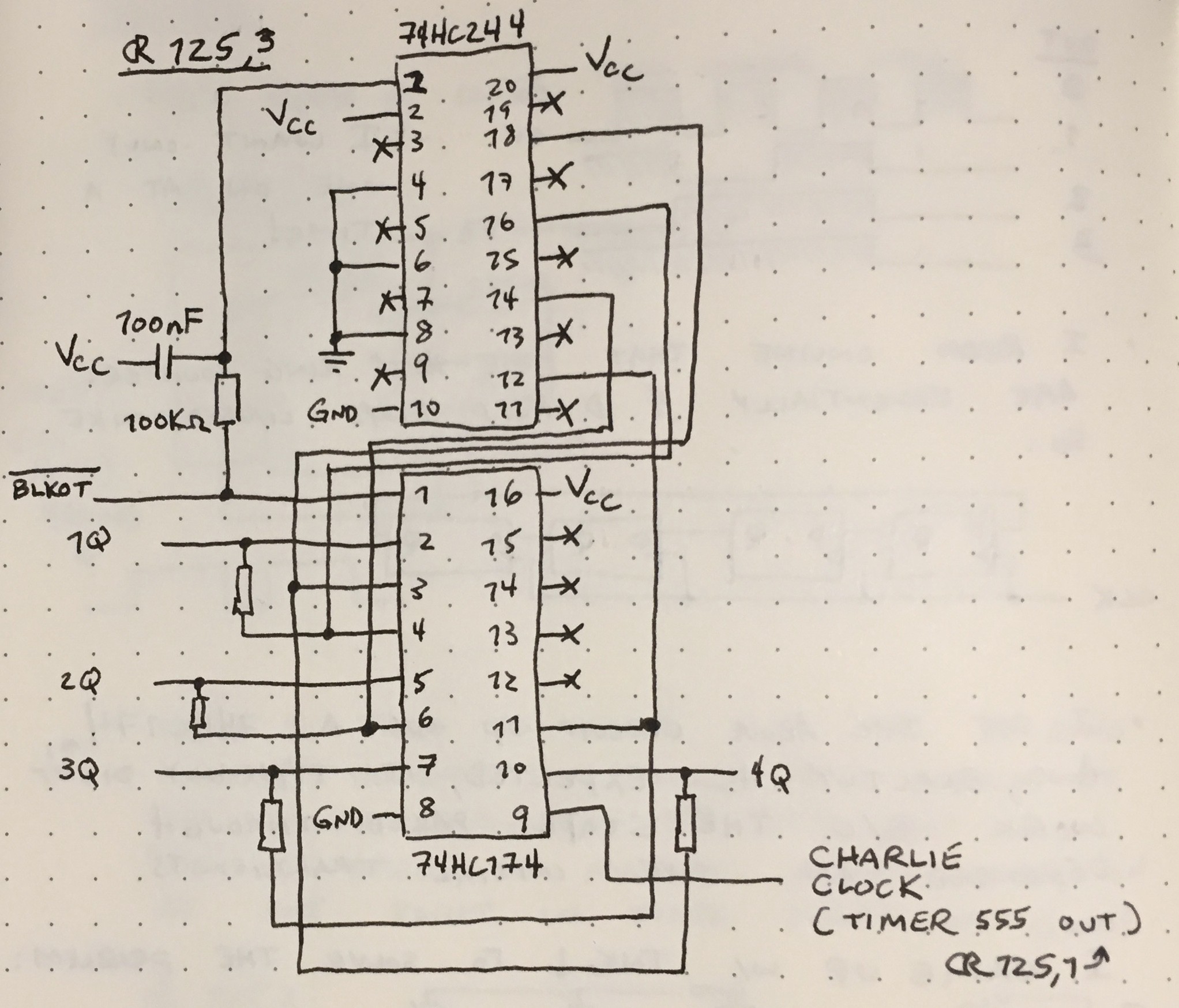
The idea is to use a 74HC244 line driver to set the initial conditions correctly whenever the Arduino brings the blackout line low (this signal is also connected to the flip flops and disable's their output, thus allowing the Arduino to turn off the displays, hence the name). An RC network is used to add a delay between the Arduino bringing blackout high and the initial condition register turning off. This guarantees a few clock cycles occur while the flip flops are enabled and the initial conditions are still held. This worked nicely also. Next I set up the shift registers and wrote an Arduino program to load data into them. I ran into some software bugs and mistakes in my wiring (one of which shorted the shift register outputs and fried a few chips - oops). I worked out all the kinks though and got the displays to show what I wanted. The only catch was that the amount of current drawn by the display from the ring counter was too much, contrary to what my back of the envelope calculations predicted. Adding a P-channel MOSFET to drive the common anodes of the display fixed this. Not shown here is a 74HC04 hex NOT gate used to invert the signal from the ring counter - the 74HC595s use active-low output enables, so do the PMOS transistors.
Here's the beast set up on a breadboard displaying demo data from the Arduino. I programmed the Arduino to display a series of characters and patterns to verify everything was working perfectly. I also only hooked up two characters to save some breadboard complexity.
Discussions
Become a Hackaday.io Member
Create an account to leave a comment. Already have an account? Log In.