 Grant Giesbrecht
I put LEDs on the underside of my shelves for my old bench and really liked the extra illumination - plus it looked cool. I'm doing the same thing for this new bench, but I'm using individually addressable LEDs and a better light mounting system.
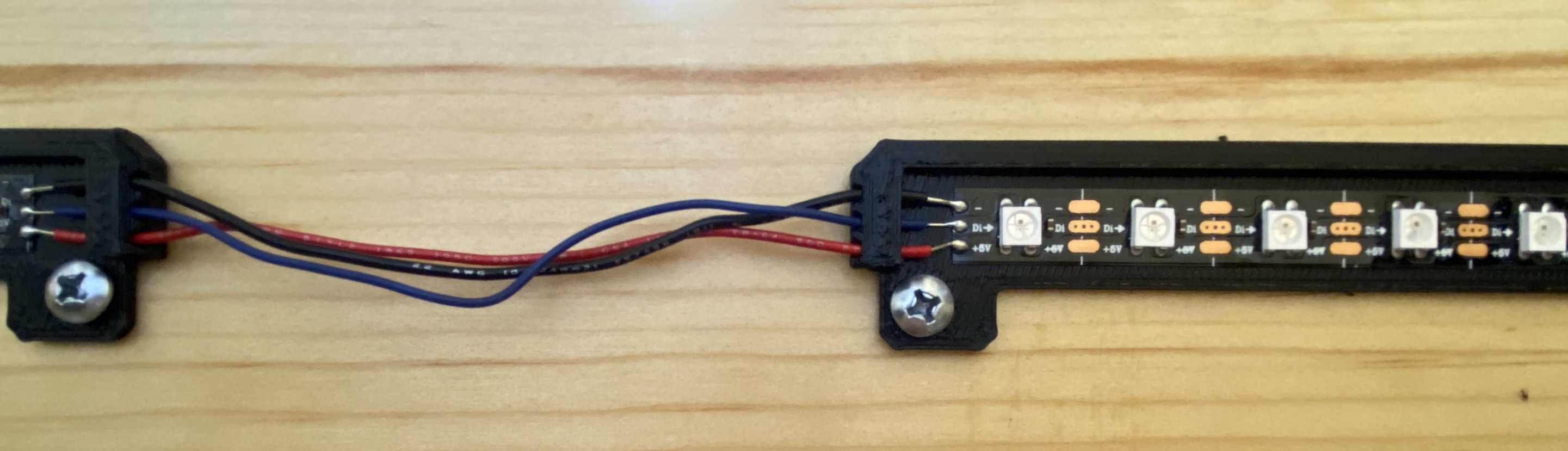
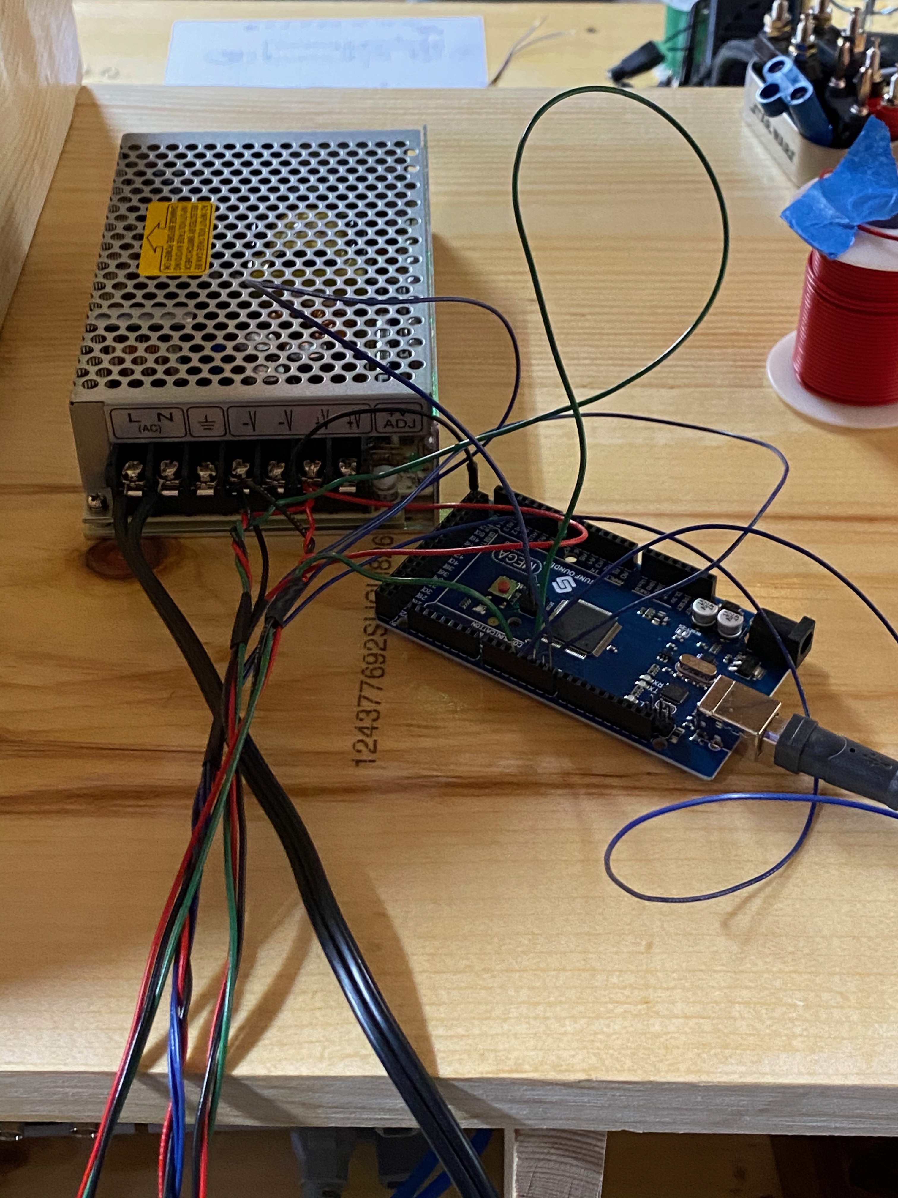
I'm using WS2812B LEDs and I'm controlling them with an Arduino Mega. I didn't want to use the adhesive that comes with the LEDs directly on my shelves because the adhesive is kinda crappy. Instead, I'll use their crappy adhesive on 3D printed mounts which will screw into my shelves. If the adhesive fails, I can experiment with other glues without worrying about damaging the finish of my shelves. More importantly, the 3D printed light mounts will also provide some rigidity to the wires, which from prior experience, really want to tear their pads off the light strip. They'll also provide a shade which hides the bright emitters for a more polished and tidy look.


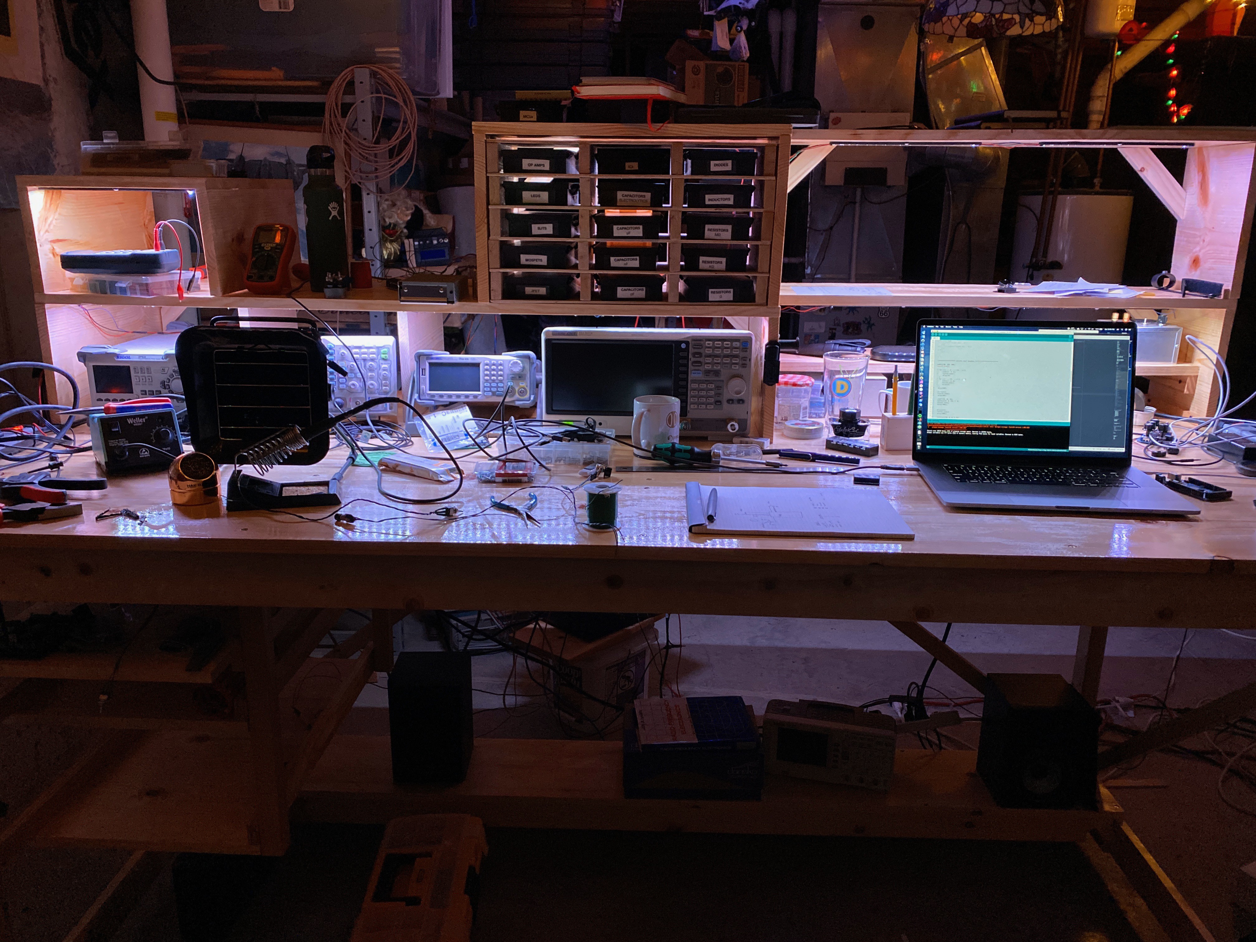
The rest is programming. In order to make it easy to make cool patterns, I estimated the relative position of the light bars and made function which understands my lights to be arranged in a grid 96 columns wide and two rows high. I can assign any color to any 'pixel' on my shelves and the function automatically locates the correct bar and turns on the LED(s). Because of the arrangement of the bars and the spacing between them, there isn't a 1-to-1 association between LEDs and grid squares. For example, the light bar behind my centrally located grid-shaped shelf holding black boxes has 16 LEDs but occupies 14 cells in my grid. Now I can make cool animations below without having to worry about the relative position of different bars, I just assign colors to pixel locations like on a screen, but the screen is actually a shelf :)

Discussions
Become a Hackaday.io Member
Create an account to leave a comment. Already have an account? Log In.