Kyle Isom
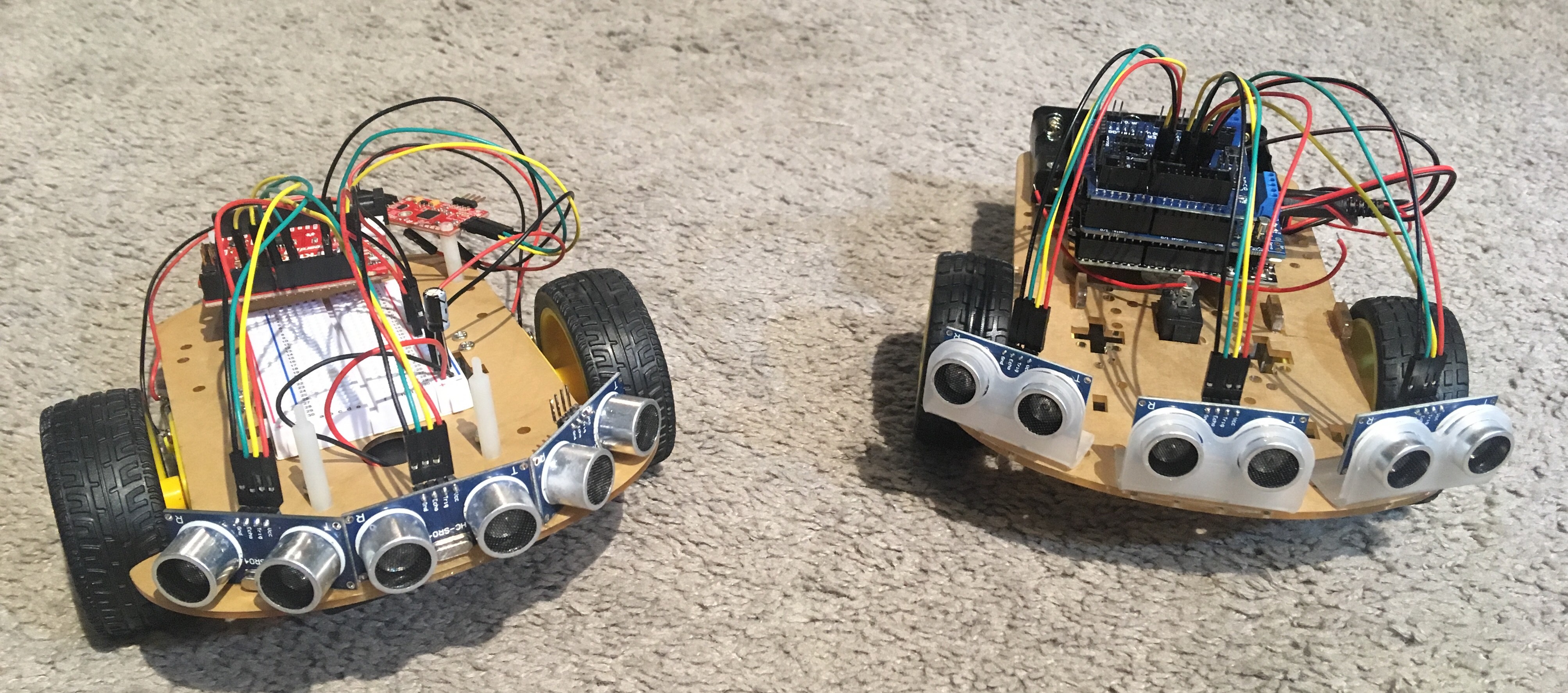
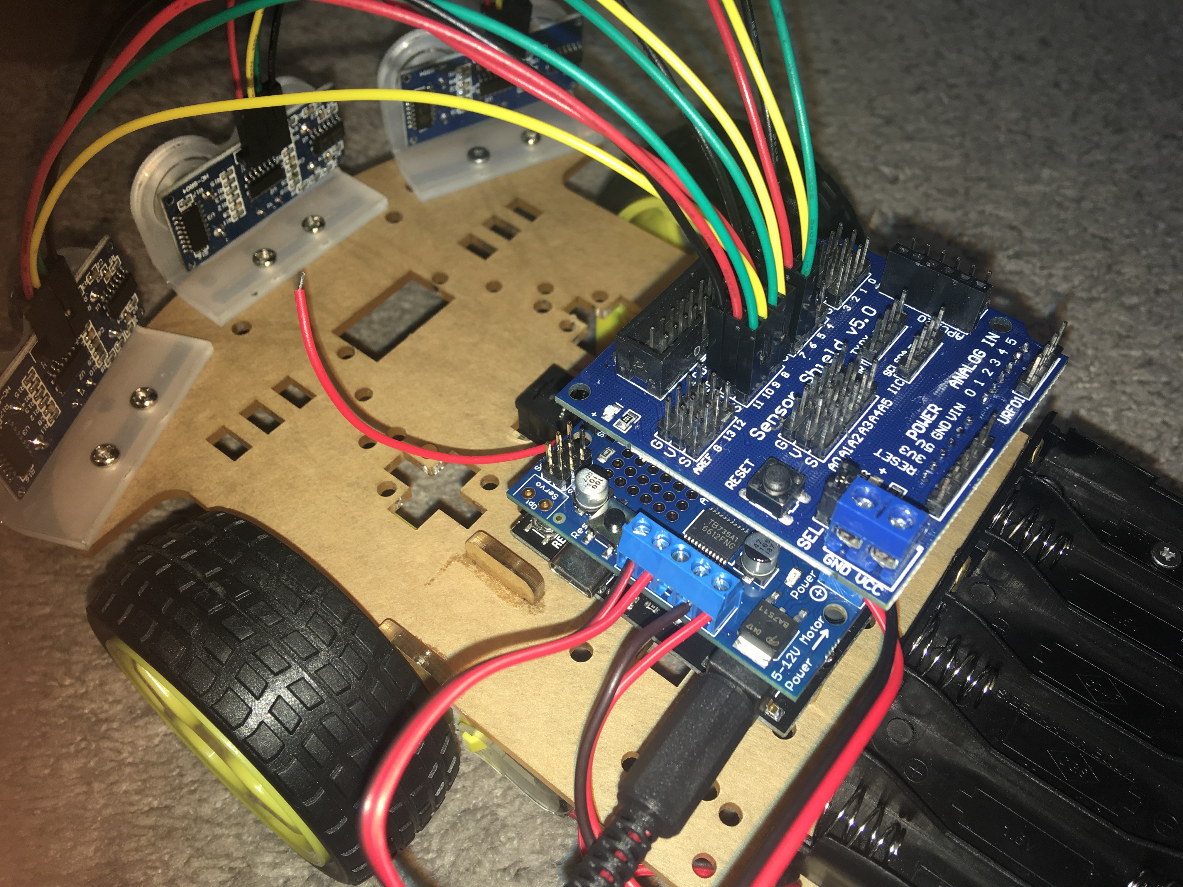
I took a self-driving car class last year, which was fun but didn't have us actually do anything tangible (unless you count computer programs as tangible). I decided to build a small robot to make some of the stuff I learned more concrete.
0%
0%
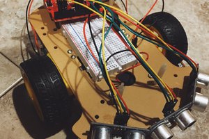
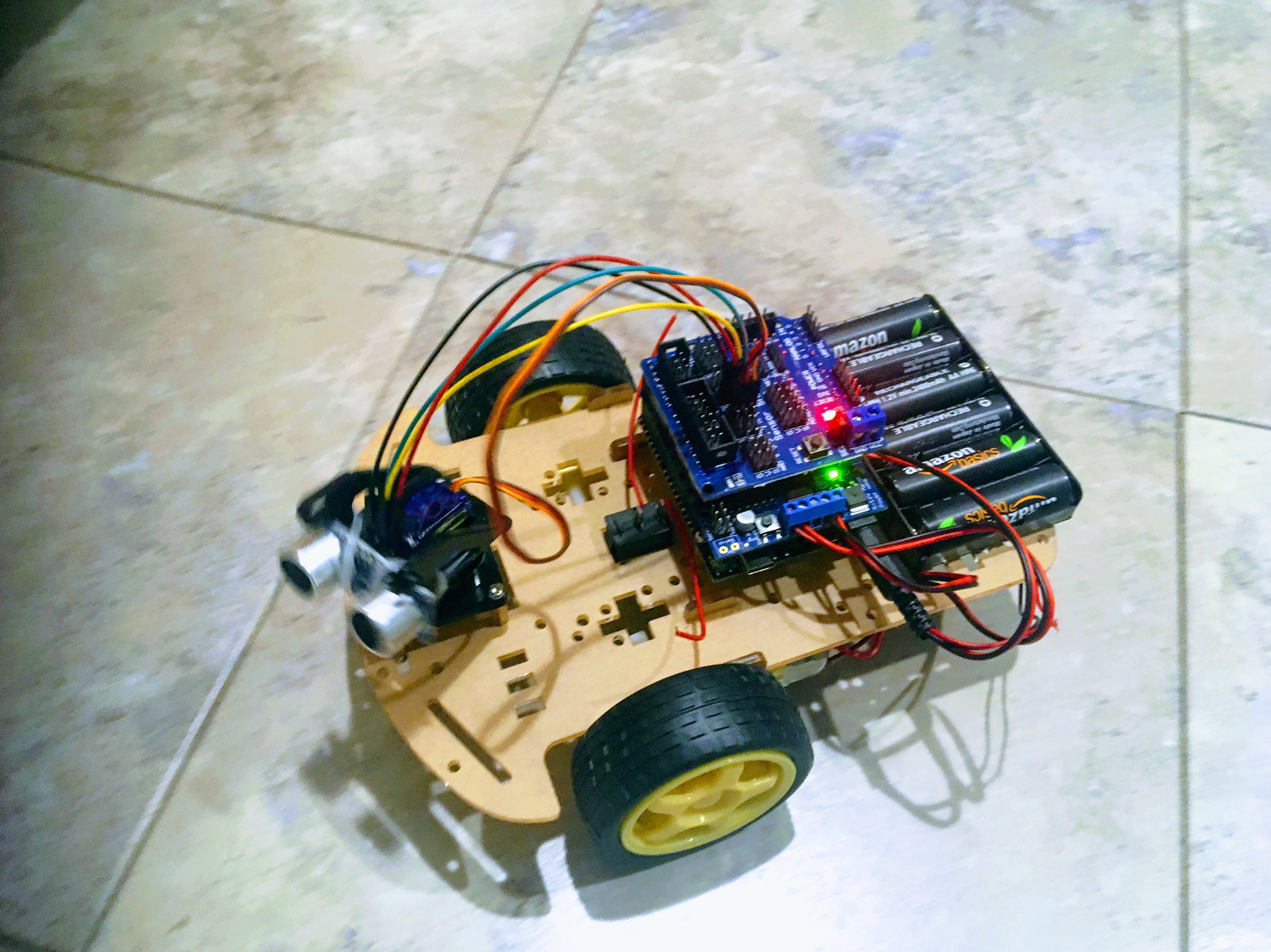
Scooter 2
A small robot to experiment with sensor fusion and navigation.
Become a Hackaday.io member
Already have an account? Log in.
Just one more thing
To make the experience fit your profile, pick a username and tell us what interests you.
Pick an awesome username
hackaday.io/
Your profile's URL: hackaday.io/username. Max 25 alphanumeric characters.
Pick a few interests
Projects that share your interests
People that share your interests
 Jacob David C Cunningham
 evive toolkit