 patchartrand
Making projects that interact with the physical world becomes challenging very quickly when its on the human scale. The need then arises for a relatively high powered servo to move objects, arms or wheels. At the moment, there is a large gap between the ubiquitous hobby servos and the semi large robotics servo. The choices are to use a large RC servo that is not too powerful or an entry level robotics servo that is expensive and complex to control.
Let’s say that someone wanted to make a remote control lawn mower (tractor, not the push type). Seems like an easy project…. Pushing, pulling and steering all the functions on the tractor requires a fair amount of force and speed. Linear actuators can do the levers but they are quite slow and will need a feedback loop with appropriate control circuit. RC servos are too weak to control any items and the industrial equipment is heavy, very expensive and complex to implement.
Second example is if someone wanted to build a robotic arm. The inexpensive answer is to use stepper motors with timing belts. The stepper motors are susceptible to loosing steps and are often oversized for the application to combat this issue. The second solution is to implement industrial or robotics servos. Both of these solutions are very expensive costing multiple thousands of dollars per degree of freedom.
The Ultra Servo is meant to remove or dramatically reduce the roadblocks to create these large projects. The design intent is to serve a wide range of clients that range from the following 2 groups:
- Someone that is only comfortable with the standard RC type of communication but can still wans to set basic settings (angle of rotation, continuous or position control, absolute positioning and how to react upon loss of signal)
- Someone that is proficient in coding/control loops that wants an engineer platform or “Lego part” to build off
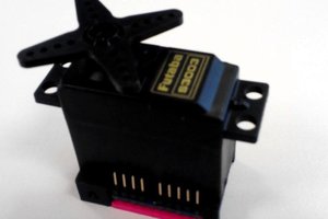
From the start I want to have a servo that is as fool proof as possible. What I mean by that is if the designer or operator makes an error, it will not burn out or break something immediately. Therefore the servo has a hard-wired current limiting, reverse voltage protection, optical isolating RC in and high toque gearbox. All these features will eliminate headaches and reduce precious trouble shooting time. After quite a bit of design and engineering, the servo will have the following specifications:
- 60 lbs*ft at stall
- 60 rpm free rotational speed
- Absolute positioning (Eliminating a homing sequence is always welcome)
- Programmed output angle range
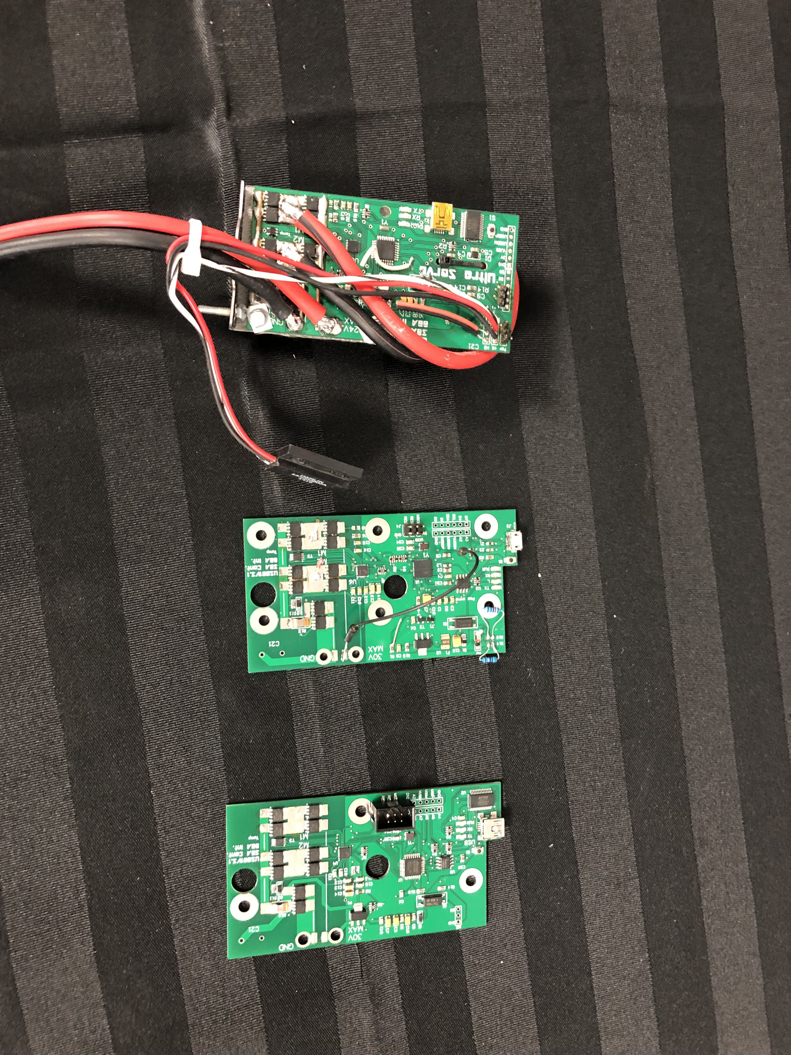
- Arduino Based micro controller
- 30A continuous motor controller
- Current sensing
- On board temperature sensing
- Brushed DC motor
- Most compact design possible
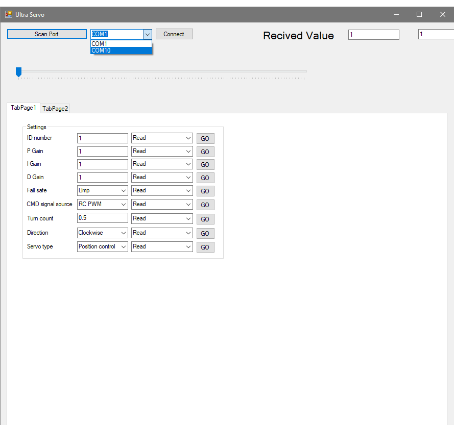
- Windows based GUI to set settings over USB to the servo
- Read real time data of the control loop and internal sensors
- Price point of 1,150 USD
There has been quite a bit of re-design and coding that has gone on since the 2017 submission. All aspects of the servo have been redesigned to make the Ultra Servo a marketable product. Below is a list of what is left to do:
- Finish the GUI interface
- Program the servo board to receive commands/settings from usb
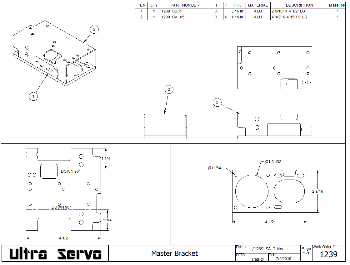
- Finish up the mechanical build to validate all tolerances
- Sticker kit
- Durability testing
Licenses:
- Circuit Maker (open source)
- Arduino Development platform (open source)
- Autodesk Inventor (Yearly subscription)
- Microsoft Office (Yearly subscription)


 Alvaro Ferrán Cifuentes
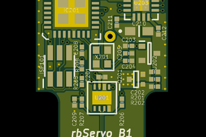
 RasmusB
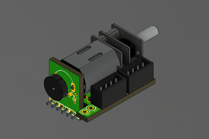
 Holotype Robotics
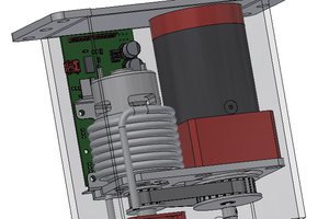
Thanks for the information on the 01mechatronics. I had no Idea they existed. They have a very nice developed product. The main focus for this servo is its strength it has 60ft lbs or 81Nm of torque. The ultra servo definetly will not have as much communication functionality as the 01mechatronics. I want it simple enough for somone that only uses RC signals (not to be intimidated) and open enough that if someone wants to go into the programming, they can.