 Andrey V
Short video about this device:
- 0:00 - description.
- 0:23 - usage for simple weight scale application.
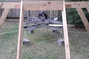
- 1:03 - usage for Automated 3-axle Truck Weight Measurement System.
- 2:47 TODO list
- 3:00 What next?
Where load cells mainly use in industry?
- Trucks weight scales
- Railway weight scales
- Conveyor weight scales
- Cranes

Attention, please! Just push "read more" for the project details, and you will find a lot of useful information about the device development!
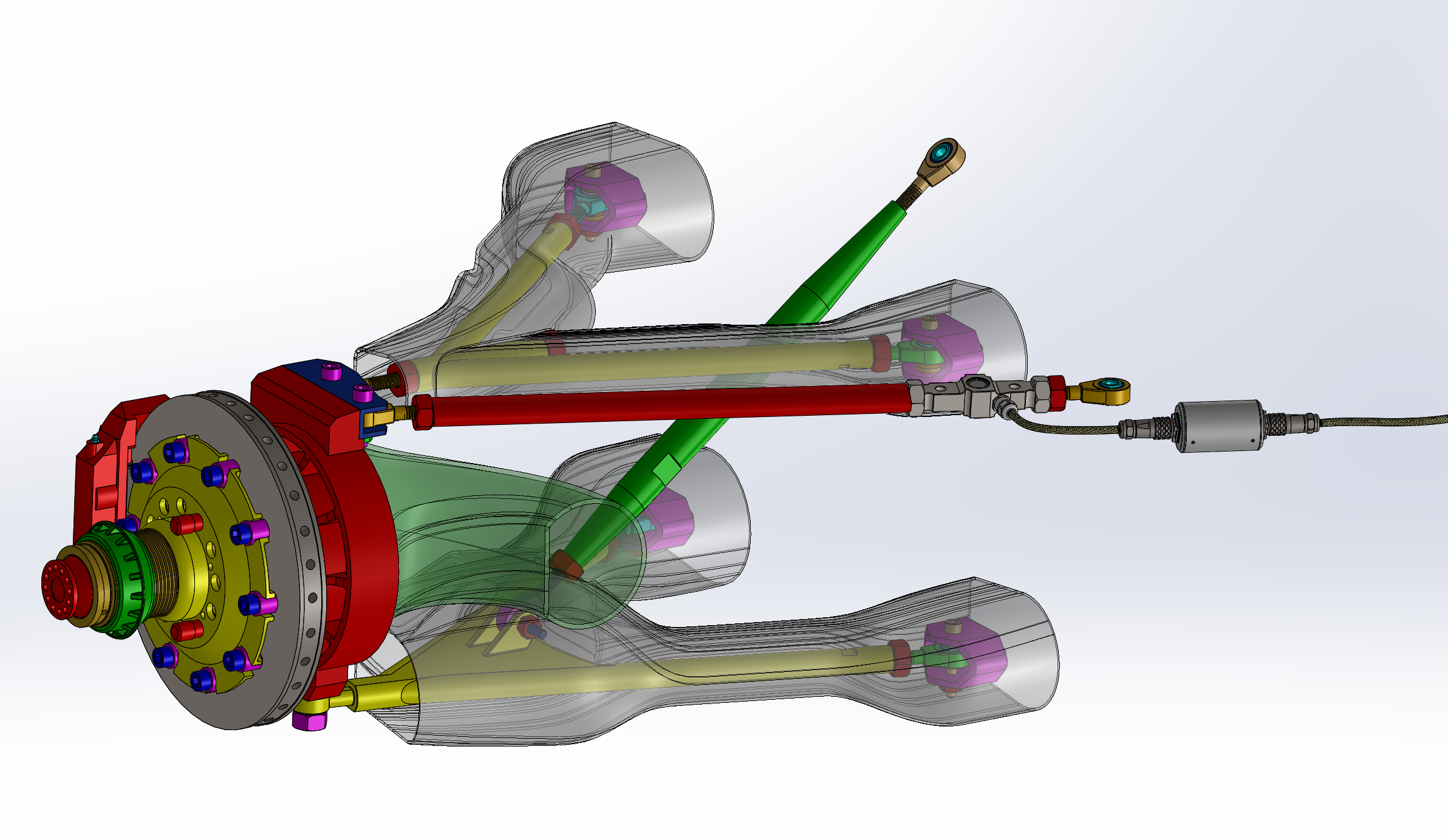
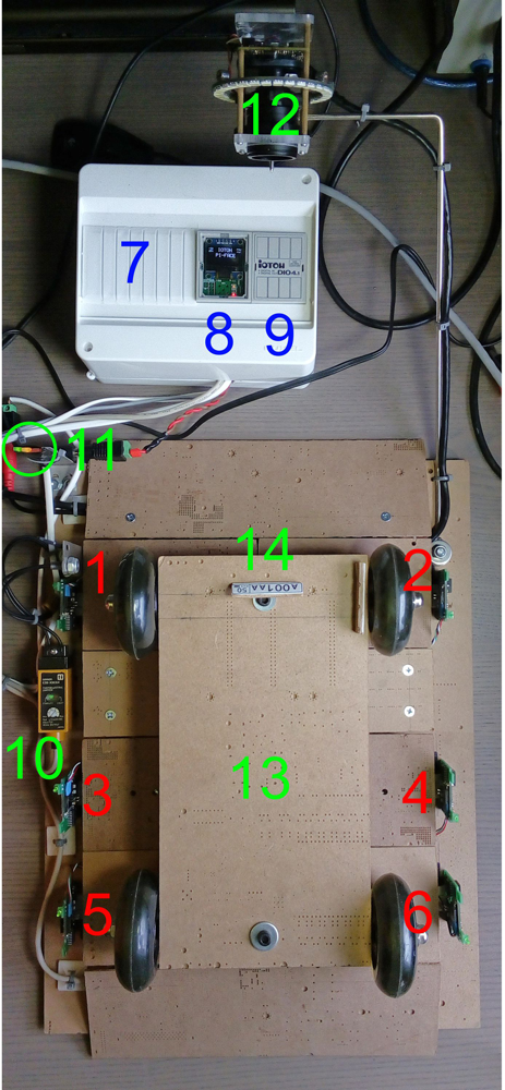
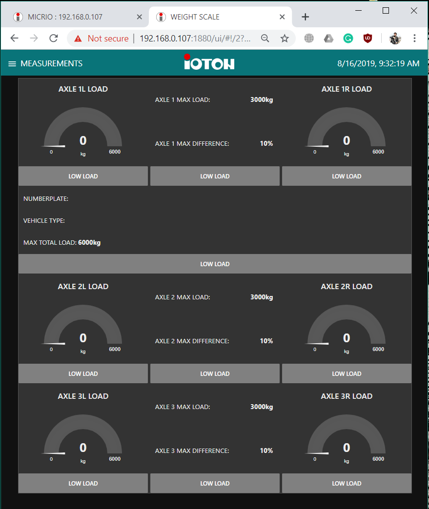
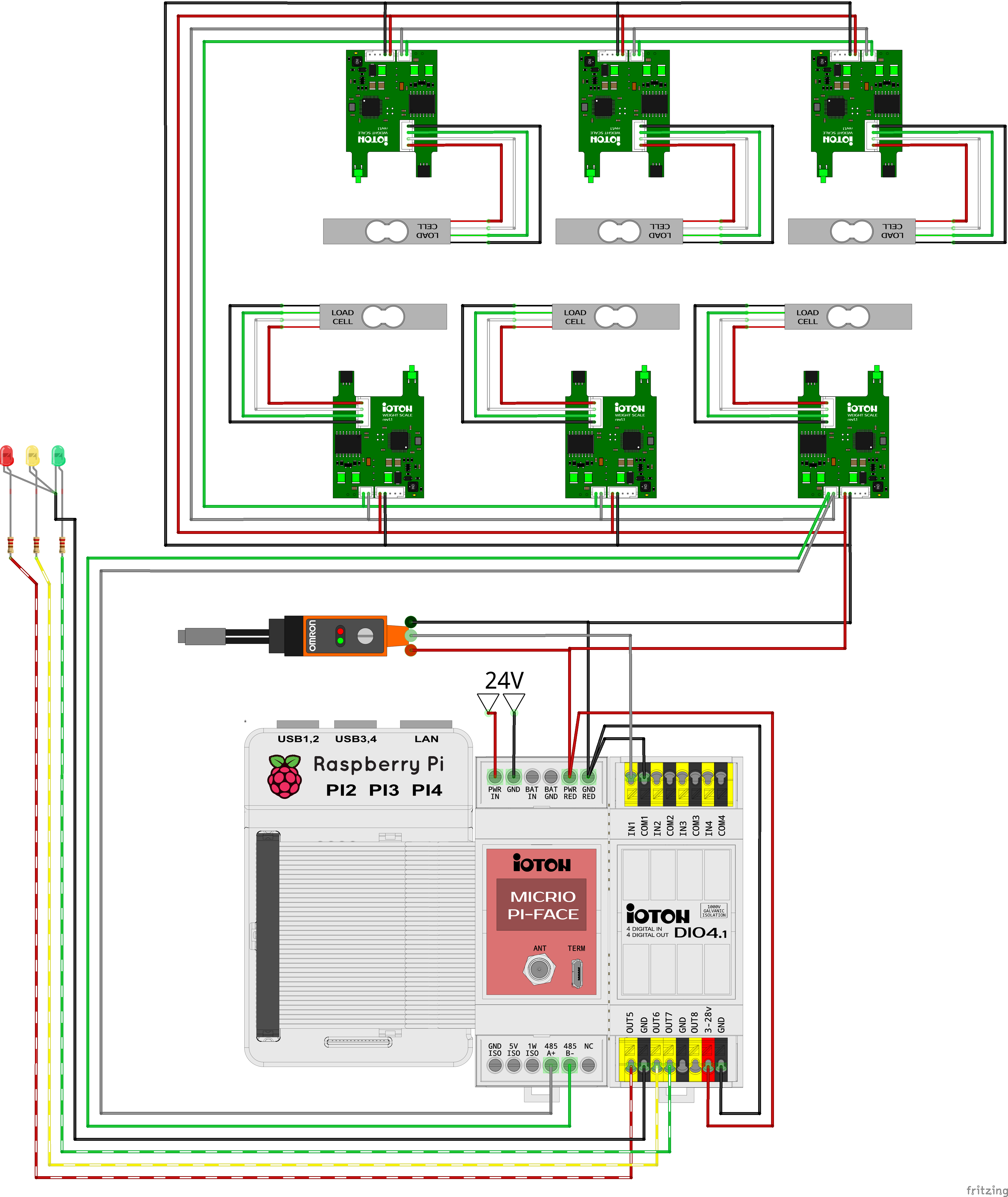
In the project log, you can find my implementation of weight scale for 3 axle trucks, and some tests.
I apologize for my bad English. Please, be patient to this fact, or show me errors, I will fix it)
I will try to post new chapter every day, but sometimes it is impossible, because I have one more large project and I need to spent some time for it. If you are interested here the link - https://hackaday.io/project/166617-ioton-micrio .
Let's start.
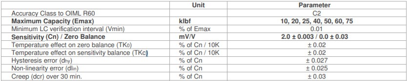
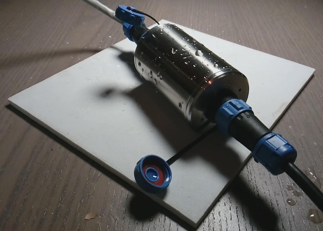
About the load cells:
Because of my bad English I will not write about load cell working principles and theory behind it (you can find enough information about it in the internet).
I stops only on weaknesses.
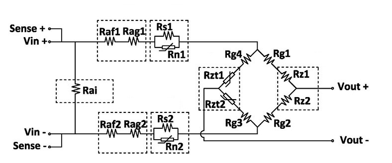
What weaknesses the load cells have?
1. Low sensitivity (typically around 2mv/V). With 5V excitation voltage, we will get only 10mv for tension and the same voltage for compression. So the noise immunity is not good, and we cannot use a long cable between the load cell and the ADC.
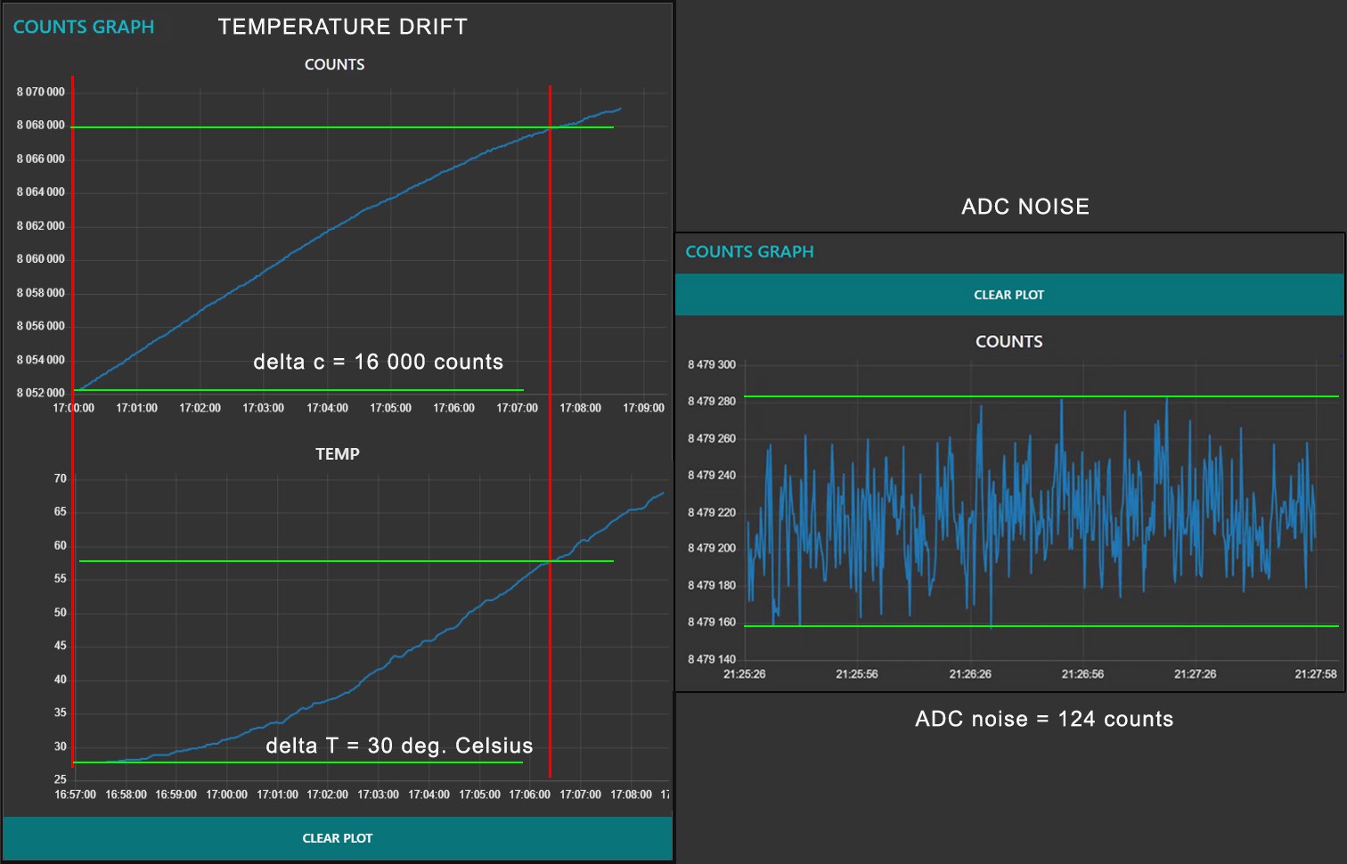
2. High temperature drift. If you put the same load on load cell you will get different results for different load cell temperatures. Also, the temperature affect on two parameters - zero balance and sensitivity balance.
About the solutions on market:
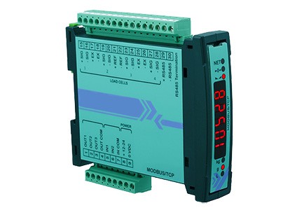
What imperfections in design for typical solutions I found on the market?*
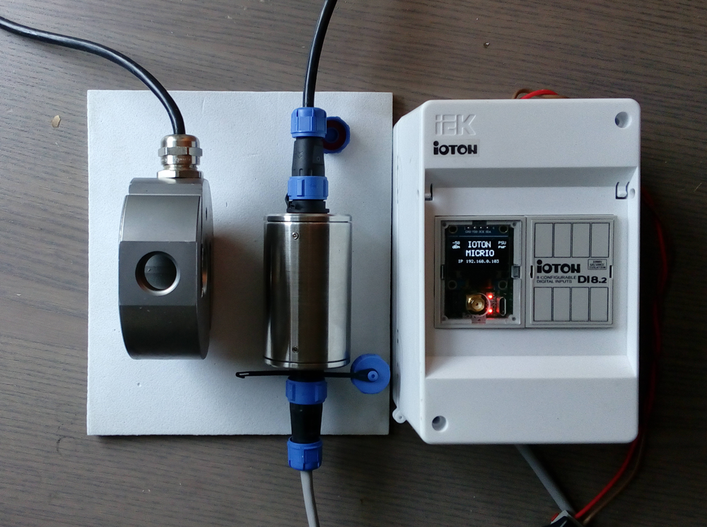
- Most of the load cell to Modbus interfaces have DIN rail mount for mounting in the electrical enclosure. In most cases the distance between load cells and electrical enclosure is significant, so noise immunity of this system is bad and we cannot do precise measurements.
- All solutions I found on market cannot do anything with the load cell temperature drift.


 Peter McCloud
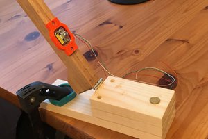
 Alexander Dvorkovyy
 Ken Meyer
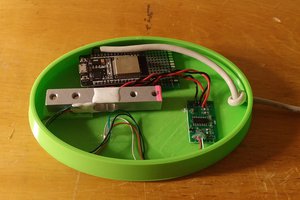
 Kevin Arne
Dear Andrey, Are you still working under one ?