 Andrey V
Short video about this device:
- 0:00 - description.
- 0:23 - usage for simple weight scale application.
- 1:03 - usage for Automated 3-axle Truck Weight Measurement System.
- 2:47 TODO list
- 3:00 What next?
Where load cells mainly use in industry?
- Trucks weight scales
- Railway weight scales
- Conveyor weight scales
- Cranes

Attention, please! Just push "read more" for the project details, and you will find a lot of useful information about the device development!
In the project log, you can find my implementation of weight scale for 3 axle trucks, and some tests.
I apologize for my bad English. Please, be patient to this fact, or show me errors, I will fix it)
I will try to post new chapter every day, but sometimes it is impossible, because I have one more large project and I need to spent some time for it. If you are interested here the link - https://hackaday.io/project/166617-ioton-micrio .
Let's start.
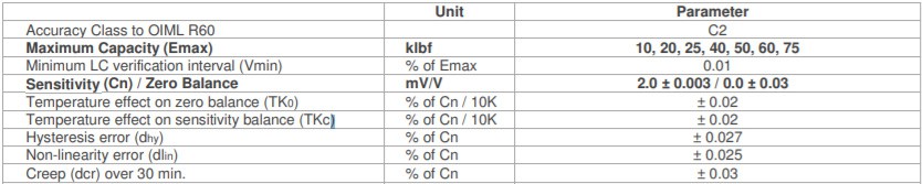
About the load cells:
Because of my bad English I will not write about load cell working principles and theory behind it (you can find enough information about it in the internet).
I stops only on weaknesses.
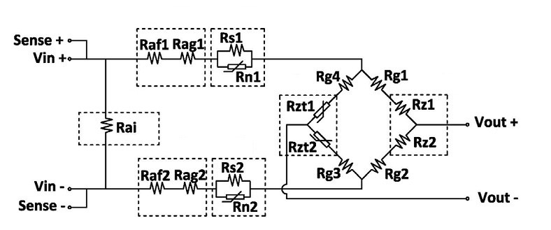
What weaknesses the load cells have?
1. Low sensitivity (typically around 2mv/V). With 5V excitation voltage, we will get only 10mv for tension and the same voltage for compression. So the noise immunity is not good, and we cannot use a long cable between the load cell and the ADC.
2. High temperature drift. If you put the same load on load cell you will get different results for different load cell temperatures. Also, the temperature affect on two parameters - zero balance and sensitivity balance.
About the solutions on market:
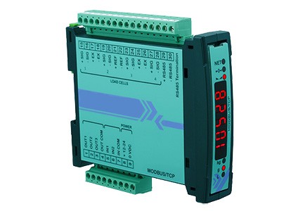
What imperfections in design for typical solutions I found on the market?*
- Most of the load cell to Modbus interfaces have DIN rail mount for mounting in the electrical enclosure. In most cases the distance between load cells and electrical enclosure is significant, so noise immunity of this system is bad and we cannot do precise measurements.
- All solutions I found on market cannot do anything with the load cell temperature drift.
My concept:
If some components in the system have weaknesses, the good engineers first thought must be 'how to eliminate it'. I thought a little about it and simple beautiful idea was born.
Only what I need is to place ADC as near as possible to load cell.
Maybe like this?
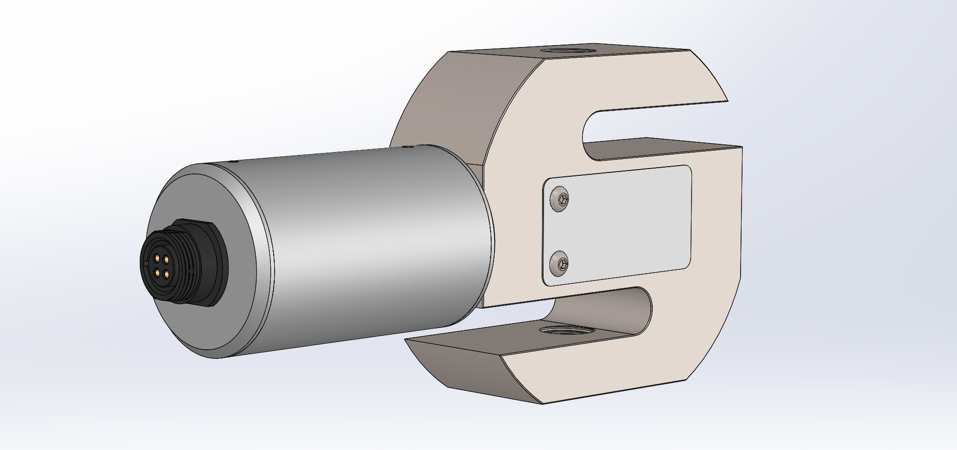
This design supposes nondestructive mount because converter mounts on the thread which load cell already have(cable gland thread).
But this design also has some weaknesses, because the load on load cell is unsymmetrical. But it will work fine with large weight capacity load cells (1000kg - 20000kg (2000lbs - 40000lbs)).
A few words about ADC:
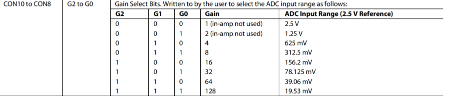
When you work with the load cells you will need a specific ADC. It's because the load cell signal is weak (typically 20mV Peak-to-Peak for 2mV/V load cell and 5V excitation voltage). If we have, for example, 2.5V ADC reference voltage we will need to amplify load cell signal x128 to get full scale from approximately 19.5mV input voltage. Some modern ADC's have internal PGA (programmable gain amplifier). So we will need to find ADC with 128x instrumentation(if you don't know what is instrumentation amplifier, please google it, its an interesting thing which can save you a huge amount of time if you do analog circuits).
Most well known ADC for the load cells is Chinese HX711, many people use it for Arduino projects e.t.c. But if you look in specs you will find it has not so good characteristics. With 90nV own RMS noise, I think the best result is around 15000 counts or around 14 bits. And all other characteristics like temperature drift e.t.c is not so good. Also, this IC doesn't have reference input...
I quickly searched an ADCs for the load cells and found a good solutions from Analog Devices:
AD7190 - very high precision (only 8.5nV RMS noise with gain = 128).
AD7799 - high precision (27nV RMS noise with gain = 128).
AD7780 - precision (44nV RMS noise with gain = 128).
So I stopped in something in the middle. AD7799 is a reasonable price good ADC especially for the load cells and it has a low side power switch for the low power consumption. I think I can achieve around 16bits noise-free resolution with this ADC.
What special about ADC settings:
At first we need to understand what we need to measure.
As I mentioned before, load cell work in both directions - tension and compression. Lets look how it works:

As we can see from pic. load cell has output voltage around 0V without load, positive voltage if I push(compress) it and negative voltage if I pull(tension) it (look carefully on the screwdriver position and sign in red circle).
So if we will measure only tension or only compression voltage we can get wrong result. For example, if we measure compression load and load cell has some tension load(Initially) we cant see this tension load, so we will get wrong results. We must measure both voltages, for tension and for compression!
But as all in our life it has an own price. In this case it's 1bit of noise free data... But, I think we can live with it. As benefit we will get an easy calibration procedure (I will write about it later).
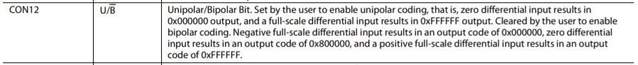
To measure voltage in both directions we need some voltage bias. It's not so trivial problem, if we talk about precise measurements. But hopefully, Analog Devices engineers gave as a good solution - bipolar coding! This option allow measure voltage in both directions with zero at 0x800000 (HEX) or 8 388 608 (DEC), max positive voltage at 0xFFFFFF (HEX) or 16 777 216 (DEC) and max negative voltage at 0x000000 (HEX) or 0 (DEC) ADC output result.
To enable this option we will need to clear(set zero) bit 12 of configuration register(page 16 manual AD7799)
Next we need to set configuration register bits 8, 9, 10. If all those bits are set we will have x128 PGA gain.
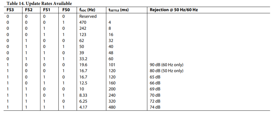
To achieve the best measurement precision we need choose the lowest update rate (4.17Hz). So we need to set bits 0,1,2,3 in configuration register.
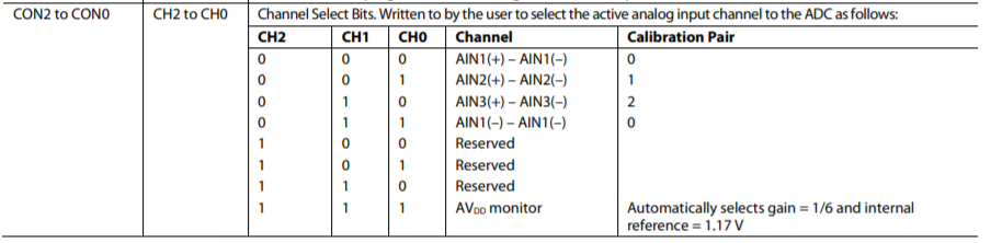
Also we need to select differential input pair ( AIN1(+) – AIN1(–) in my case), set 0 bits 0, 1, 2 in configuration register.
And last steps:
Enable burnout current bit 13 on configuration register (to see load cell health status).
Put ADC in continuous conversion mode (clear bits 13, 14, 15 on mode register).
Enable reference detect (set bit 5 on configuration register).
p.s. Yes I know, work with registers is so boring thing, but we can't go any further without it)
How to read ADC data:
On Analog Devices website I found .zip archive AD7799 Generic Driver. It contain 2 libraries written on C. First library (AD7799) for work with ADC registers and second (Communication) for communication settings, which depends of micro-controller your use.
In this project I use STM32F103C8T6 - most well known inexpensive micro-controller from STMicroelectronics. I know it is not most cost-effective solution, but in my opinion it's a good compromise.
For configure registers I used only 1 function from library:
void AD7799_SetRegisterValue(unsigned char regAddress,
unsigned long regValue,
unsigned char size);
Pay attention on format of data you put in register. For example, you need to set all 16 bits of the register (put 1 in all of it). If you are attentive you can see unsigned long(32bit) type for regValue. How to deal with it? You will need to put 16 bits in the middle of 32bit value like this regValue = 0x00FFFF00.
In my case I put in CONFIG register 0x00071000 and in MODE register 0x00000F00.
That's all for initial settings.
All procedure to read ADC looks like this:
Run once:
AD7799_Reset();
AD7799_Init();
AD7799_SetRegisterValue(AD7799_REG_CONF, 0x00071000, 3, 0);
AD7799_SetRegisterValue(AD7799_REG_MODE, 0x00000F00, 3, 0);
Run every time you need to read ADC data:
resultUnchecked = AD7799_GetRegisterValue(AD7799_REG_DATA,4,0);
statreg = AD7799_GetRegisterValue(AD7799_REG_STAT,3,0);
Maybe you wondered, why I need to read STATUS register every time? I will explain it later)
How to avoid ADC data errors:
"If you didn't make any errors, probably you did nothing." Maybe it's only words for somebody, but for me, it's a truth of life.
Sometimes the errors appear where you do not expect it at all. Something like this happens in this project. In this small chapter, I'll write how to avoid it.
As you read before I used 24bit ADC, so I need to read only 24 bits of data to get a correct ADC result. But 24 bits is no standard format for C variable, therefore AD programmers wrote a library to read 32bit. When I put 24 bits in 32-bit variable I expected to see hex result like this 0xFFXXXXXX or 0x00XXXXXX (XXXXXX - 24-bit data). In my case, it was 0xFFXXXXXX.
My first thought was extracting 0xFF000000 from it to get a clear 24-bit result. And I did it. But something really bad happened. When I tested the system and put results on the graph, I found - sometimes results of ADC conversion was absolutely wrong and out of 24 bits range. And this happens absolutely randomly. After some time of debugging, I found that sometimes I got 0x7FXXXXXX instead of 0xFFXXXXXX. I don't understand why ADC acts like this and I decided to eliminate the problem somehow.
Reading only 24 bits is not a solution, because In this 24 bits I will have only 16 bits of ADC data (because of the data order). So I decided to clear the first 8 bits. I did it bit by bit.
result &= ~(1UL << 31); // clear 8 first bits
result &= ~(1UL << 30);
result &= ~(1UL << 29);
result &= ~(1UL << 28);
result &= ~(1UL << 27);
result &= ~(1UL << 26);
result &= ~(1UL << 25);
result &= ~(1UL << 24);
Also, it is possible to do it in for loop.
After that, I tested the system and it works like a charm.
But two last things I need to check:
1. Does ADC input signal in range? (health status of the Load Cell)
2. Does ADC reference voltage is good?
How to check ADC signal range and reference errors:
As I wrote before, AD7799 has a STATUS register, let's look:
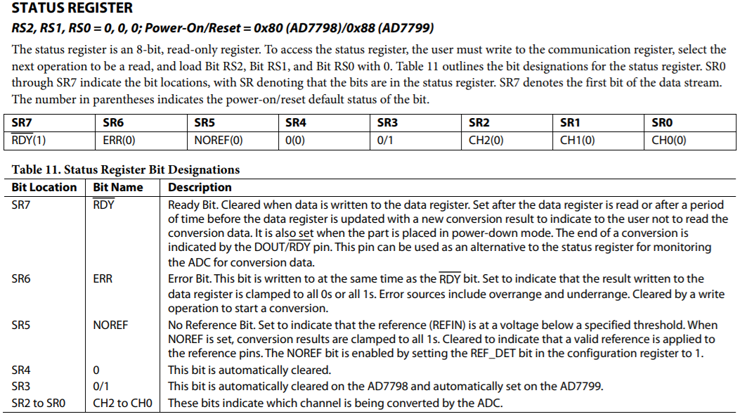
As you can it has SR6(error bit) and SR5(noref) bit. Normally, after a successful reading AIN1 channel, this register equal 0x88 HEX (for AD7799). So, why not check this register after every conversion, and if it not 0x88 we will know something bad happened. I did It like this:
resultUnchecked = AD7793_GetRegisterValue(AD7793_REG_DATA,4,0);
statreg = AD7793_GetRegisterValue(AD7793_REG_STAT,3,0);
if(statreg != 0x88FF){ // if ADC error (ADC 7793 not 88FF) (ADC 7792 not 80FF)
AD7793_Reset();
AD7793_Init();
AD7793_SetRegisterValue(AD7793_REG_CONF, adcGainHEXvalue, 3, 0);
AD7793_SetRegisterValue(AD7793_REG_MODE, placeToRegMode, 3, 0);
result = 0;
inReg[7]++; // sum of ADC errors
}
if(statreg == 0x88FF){ // if no ADC error (ADC 7793 88FF) (ADC 7792 80FF)
result = resultUnchecked;
}
As you can see from code, if the STATUS register is not 0x88 I just reset ADC and add 1 to error counter (I can read it from one of modbus input register).
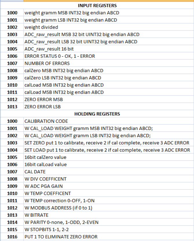
WEIGHT SCALE MODBUS registers:
MODBUS LIBRARY I USE:
One of my subscribers asked me about modbus library I use. So, it's time to give an answer.
My product is for commercial use, therefore I asked my friend from Nizhny Novgorod to write library for me. This library works only in RTU mode.
If you want to repeat my project for non commercial use, I can advise you a great library https://www.embedded-solutions.at/en/freemodbus/. You will need to spent some time to port it for the microcontroller you use, but if you will do it, you will have endless Modbus possibilities. This library works in RTU, ASCII and TCP modes. I tried it, it's really great!
CALIBRATION TROUBLES:
When I was writing the code for calibration. I made a mistake, like a child. Pay attention to it, and don't repeat my mistakes.
To calibrate load cell I need the next parameters
calZero - ADC data with zero load on the load cell
calLoad - ADC data with load on the load cell
calLoadWeight - weight of the test load
calCoeff - load coefficient
adcResult - current ADC data
weight - weight in grams
The calibration formula is simple:
calCoeff = (calLoad - calZero) / calLoadWeight
weight = (adcResult - calZero) / calCoeff
What I did wrong!!!
I assigned (int32_t) data type to the "weight" variable.
What happens next?
As weight variable has (int32_t) data type, in the next formula:
weight = (adcResult - calZero) / calCoeff
(long double) calCoeff will be rounded to an integer number before calculation. The calCoeff is not so big number, so rounding adds significant error in the result. It's not so easy to see and understand, what happens.
To fix this problem I declared "weight" variable as (long double) and add an additional variable (int32_t) weightInt.
Final code for the calibration looks like this.
calCoeff = (calLoad - calZero)/ calLoadWeight;
weight = ((long double)adcResult - (long double)calZero) / calCoeff ;
weightInt = (int32_t) weight;
After that, all work flawlessly.