 Kevin Arne
New Boards
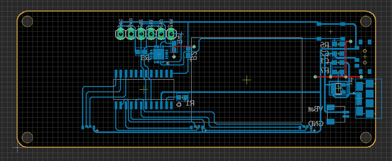
I finally decided to take the plunge and make my name tag programmable. I'm using an ATTiny85 in a QFN package coupled with IS31FL3218 LED driver (I2C) in a SOP footprint, and 155124M173200 RGB right-angle LEDs. The LED driver is PWM dimmable and has 18 channels (twice as many as I need). I also added a tact switch so I can potentially cycle through different display patterns. The LiPo charging circuit is identical, albeit re-positioned.
Difficulty with Assembly
I had some difficulty soldering the board. I tried lasering solder stencils out of mylar, but had some trouble getting the solder paste to stick to the board instead of my stencil. The laser left slightly ragged edges (unusual for lasers, but I don't usually use them on this scale), which may have caught the solder paste when I went to remove the stencil.
All of the RGB LEDs ended up tombstoned out of the oven (basic toaster oven) and had to be reworked with a hot air station. It appeared that the ground pad of the ATTiny85 also ended up bridged to the other pins, so that also had to be reworked. Finally, it turns out the manufacturer's suggested footprint for the LED driver was a bit too small.
I'll just use a hot air station for the whole thing if I make another one.

Programming Issues
Following the manufacturer's description of the registers and auto-increment features, I put together a test sketch (using Arduino IDE) meant to turn all of the LEDs on and off...
No signs of life, probably should've at least included a status LED of some sort.
Next, I uploaded a sketch that blinked one of the pins broken out to the programming header and watched the voltage change with my multimeter. That worked just fine, so I knew the problem was either with my code or the LED driver.
I consulted a friend at my makerspace who knows much more than I do about these things. He found a test sketch from the manufacturer, not using the auto-increment feature (and dividing the I2C address in half, which I don't understand). With a few tweaks (Wire.h -> TinyWireM.h) I got that code to run and flash my LEDs, which confirmed that my code was the issue.
I removed the auto-increment feature in my code (and also divided the address by 2, again, don't understand that) and was able to get the code running smoothly.
To Do
The next difficult part is figuring out how set up the interface for the LEDs in such a way that I can easily create the light patterns I want. I suppose I'll need to figure out which patterns those are first.
Once I have a couple of patterns, it'll be easier to debug a state machine using the button. I'd like to be able to switch between patterns using that button.
Finally, I need to figure out all of the non-electrical components, like the housing and heat-bent acrylic.
Discussions
Become a Hackaday.io Member
Create an account to leave a comment. Already have an account? Log In.