Close
0%
0%

Symbol LS4208 barcode reader retrofit

I have had a broken Symbol LS4208 barcode reader laying around for a while. I decided to give it a new life.

Similar projects worth following

I needed a 1D barcode reader, and had only a broken one.  It had some mechanical issue: it shot the laser beam with strange elliptic shape and could not read any barcode.

I came across recently on ebay some off the shelf CCD based barcode modules with price range 20-25 USD, so I decided to try to mount one in the Symbol's body.

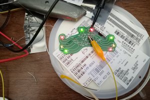
The module received it performs with acceptable results, so I did some hookup wire based experiments.

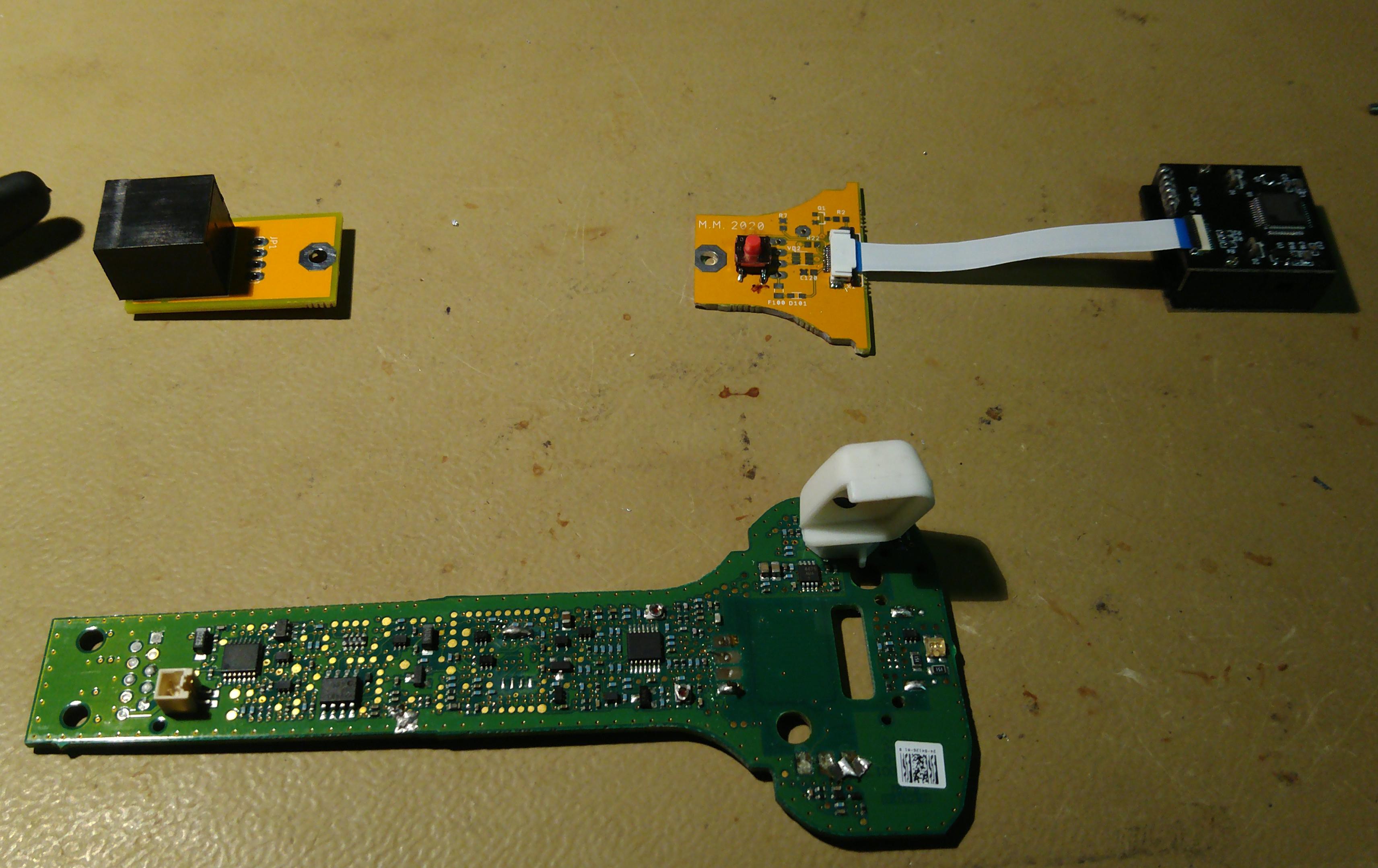
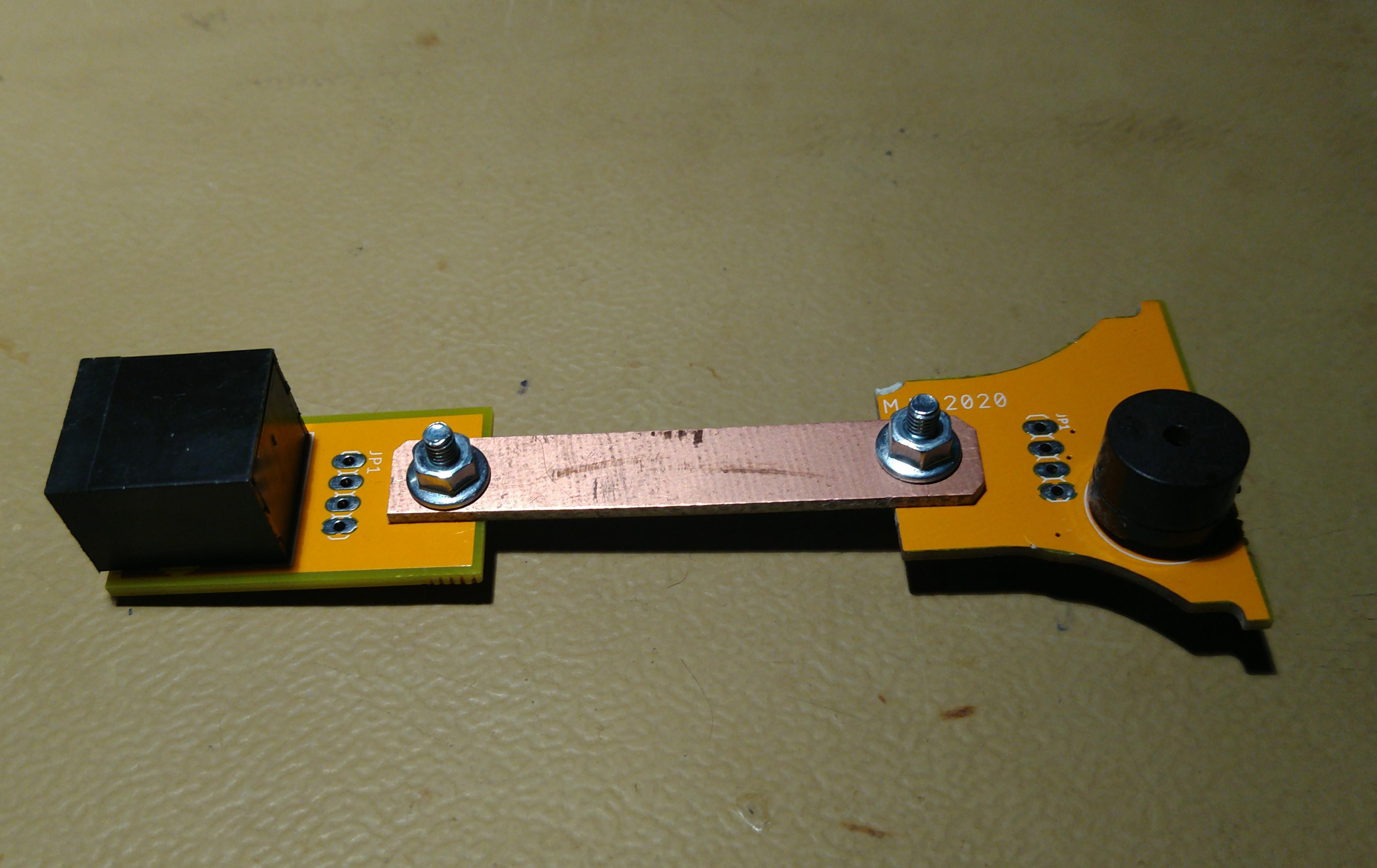
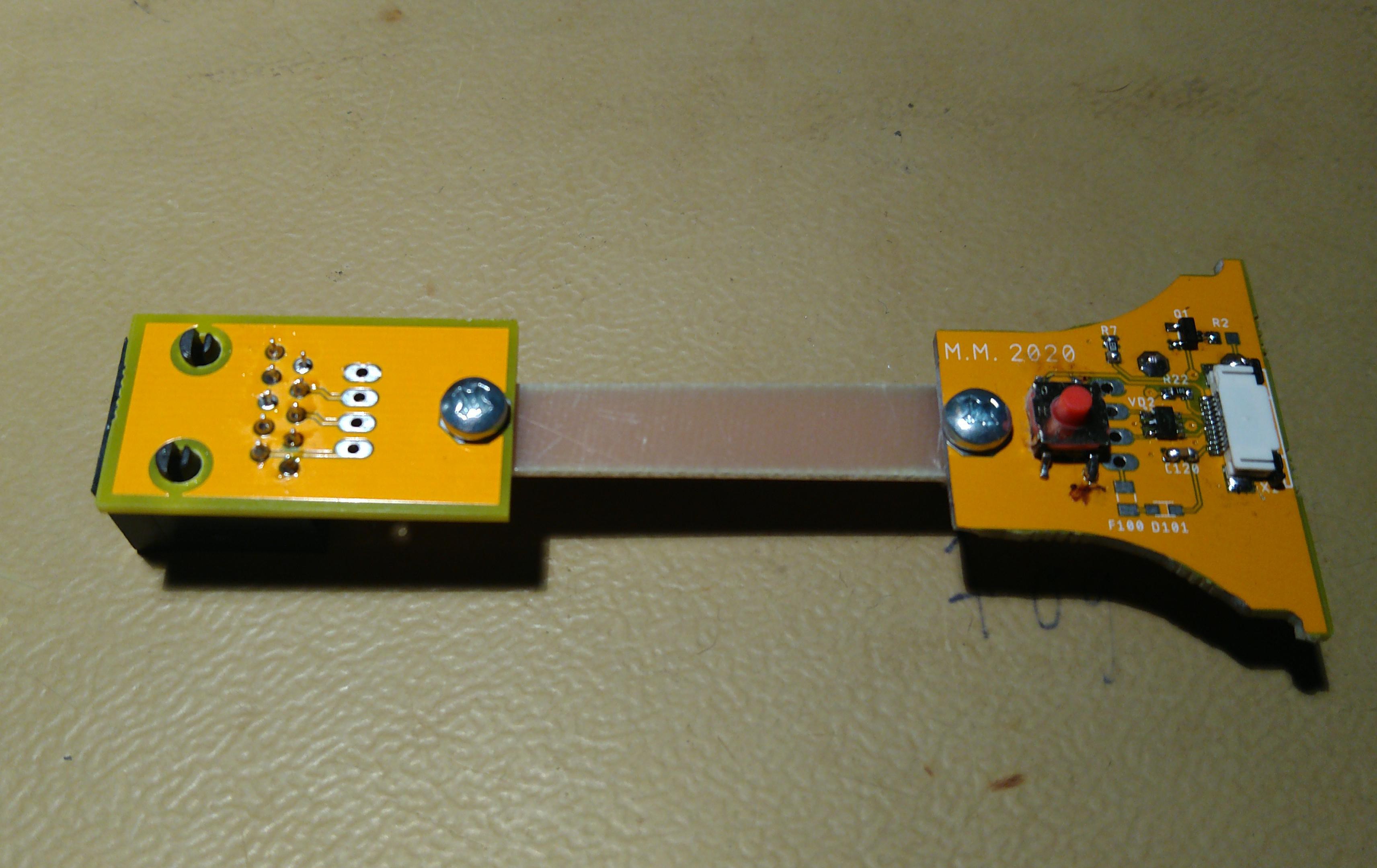
I have decided to design some replacement PCBs for hosting the bottom RJ50 connector, the beeper, the fire button and the module connector.

LS4208_SST25LF040A.bin

Backup from the SPI flash on the original board. Who knows when will someone need it.

octet-stream - 512.00 kB - 08/01/2019 at 16:23

Download

(EN)E1005(E1002) user guideV2.0.2.pdf

YK-1005 datasheet which includes pinout

Adobe Portable Document Format - 1.54 MB - 07/30/2019 at 22:07

Preview
Download

  • 1 × Symbol LS4208
  • 1 × YK-E1005

  • PCBs lessons learned

    Miklos Marton06/16/2021 at 21:53 0 comments

    The good:

    - PCB shapes turned out to be good. The PCB was scanned then vectorised and then imported to EAGLE. This process worked out fair enough.

    The bad:

    - The footprint of the salvaged pushbutton is small (damn I have skipped the always verify footprints on a printout before PCB ordering) Using multiple device footprints in these cases usually a positive thing.

    - Always add more info on the silkscreen if possible: having the USB coloring present would have been helpful

    - When making single boards like the RJ50 side make it universal: I should have broke out all the 10 RJ50 pins to pinheaders, then it could have been repurposed for other things in the future.

    - The ESD protection TVS was not at hand instead I populated NUP4302. However that part does not have connection between the in and out pins. Some extra green wiring was necessary.

    The lucky:

    - There were some DRC errors: the beeper pad overlapped with one connector pad.Luckily the connector pad was not connected to anywhere.

  • PCBs arrived

    Miklos Marton06/16/2021 at 21:41 0 comments

    I fitted one PCB set to my last dirtyPCBs order, and received them:

    As you see I made two separate PCBs to spare board space.

    The RJ50 and main boards will be connected with a blank PCB strip:

View all 2 project logs

Enjoy this project?

Share

Discussions

Similar Projects

Does this project spark your interest?

Become a member to follow this project and never miss any updates