 Mastro Gippo
 Now that I tested and improved the proof of concepts for power, energy measurement, control and car interfacing, I can merge everything in a single block that fits in a nice box. As discussed in the enclosure post, I choose to use a 3DIN standard box so I looked around for options.
I was pretty lucky to find a reputable manufacturer 5 minutes from home, and decided to test their 3MXTSC box:
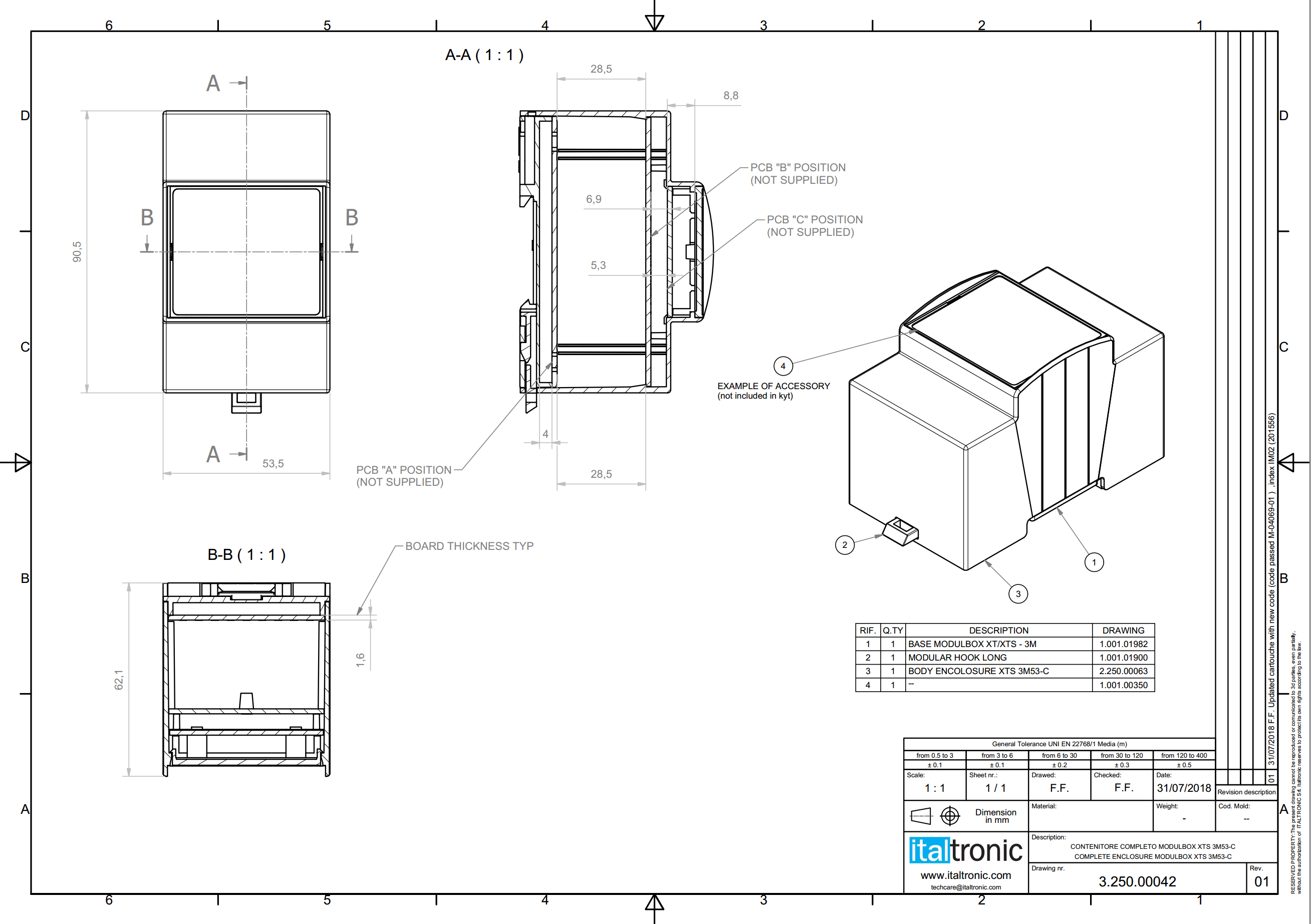 Documentation for this product is very good, and it was pretty easy to model the PCB outlines after their technical docs. Having a lot of stuff going on, it was pretty clear that I had to spread all the electronics on at least two PCBs. How do we split functionality? The constraints of this problem are to keep connections to a minimum and put the high voltage stuff all together with good isolation.
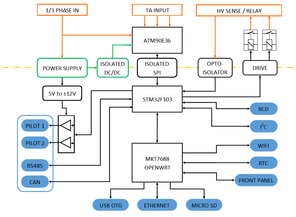 It's clear that a good option would be to separate everything along the yellow line, leaving the High Voltage stuff on the bottom board and putting everything else on the top one. However, while designing this board I found that there was a lot of space left so I started including more and more stuff, like the STM32 and driving circuitry for the Pilot signal, so I ended up placing almost everything there:
I also had to think of a way to connect the boards together. I've seen many manufacturers using flat cables or big connectors for similar applications in DIN boxes, but if you read the front cover article you'll know that I love using PCBs in weird ways. So I decided to use two vertical PCBs as "bridges" to connect the boards sides, as they fit perfectly in the DIN box slots:
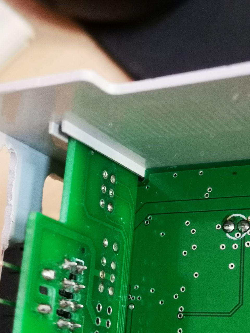
Oddly enough, the distance between this vertical board and the plastic shell perfectly fits a vertically mounted Molex connector like the ones I'm using on the bottom board, and everything lines up nicely:
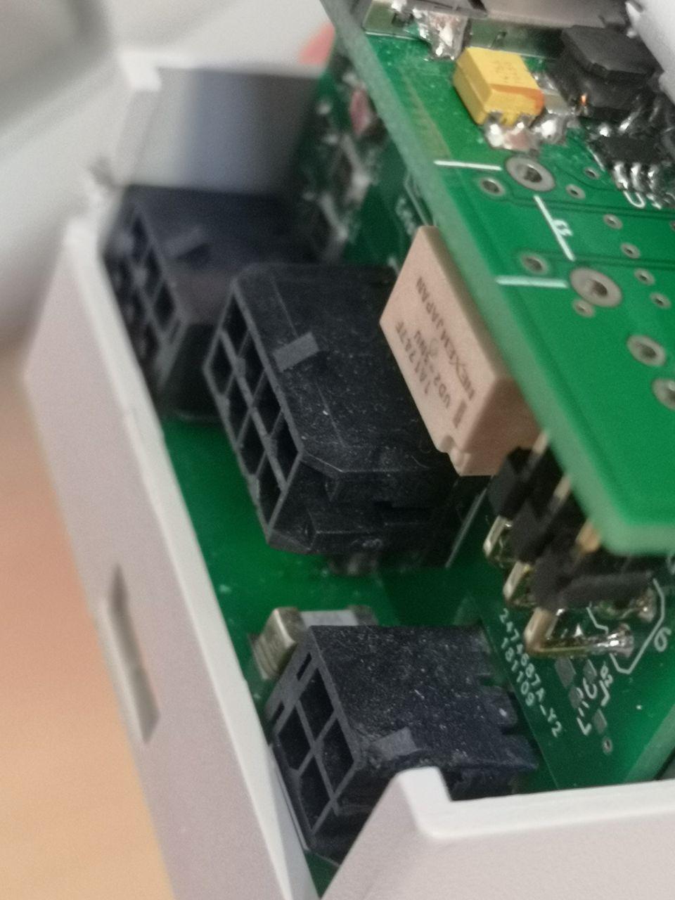 This vertical board also hosts the relays to drive the contactor and optocouplers to detect the high voltage on the contactors output. It's connected to the top and bottom boards with standard 90° 2.54mm pin strips, but due to size constraints I couldn't use matching female connectors so I had to solder them to the boards.
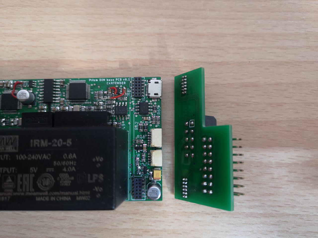
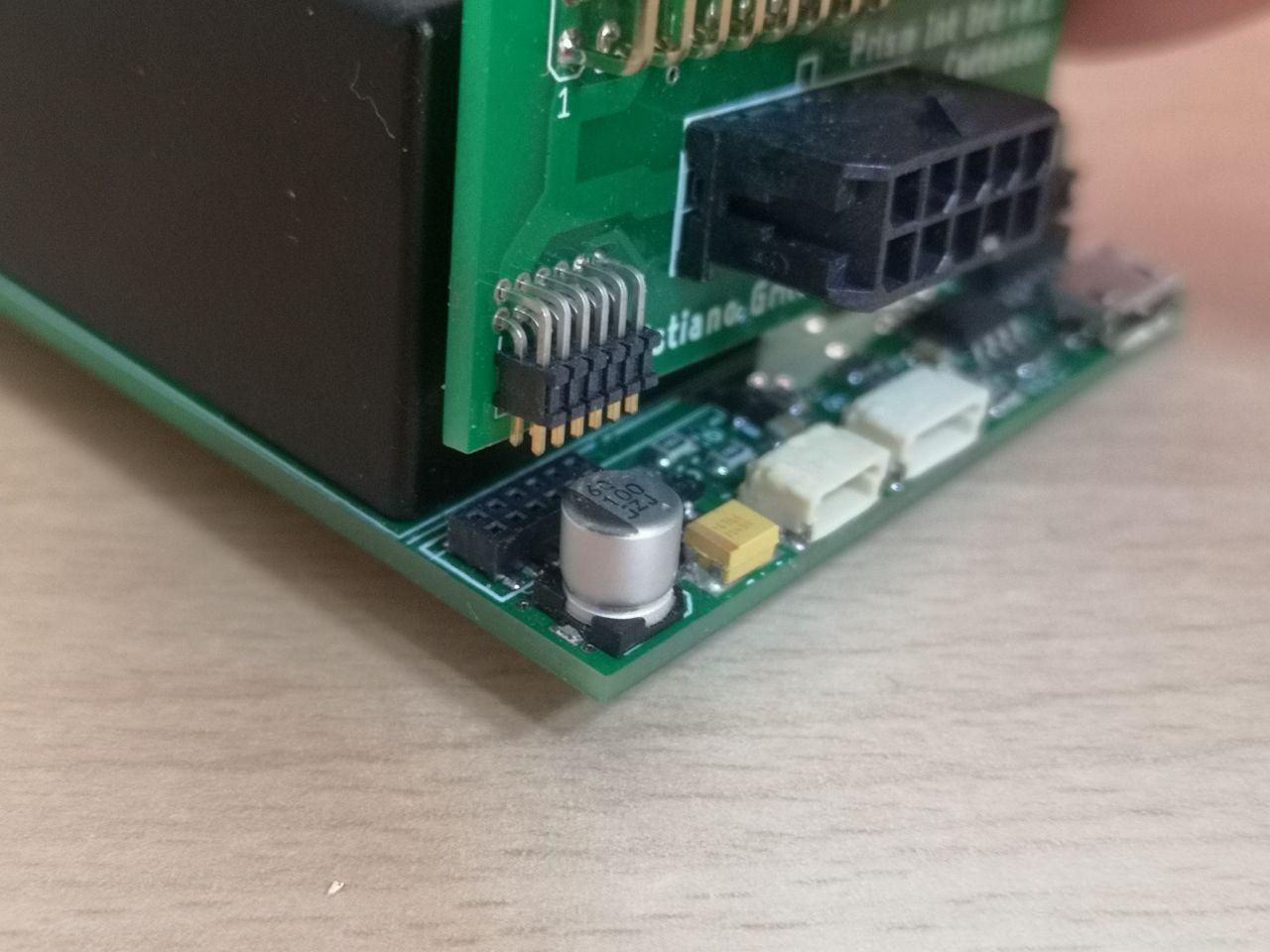
On the other side I didn't have much space to fit vertical connectors, so I opted for the cute tiny SAMTEC CLP-106-02-F-D-P:
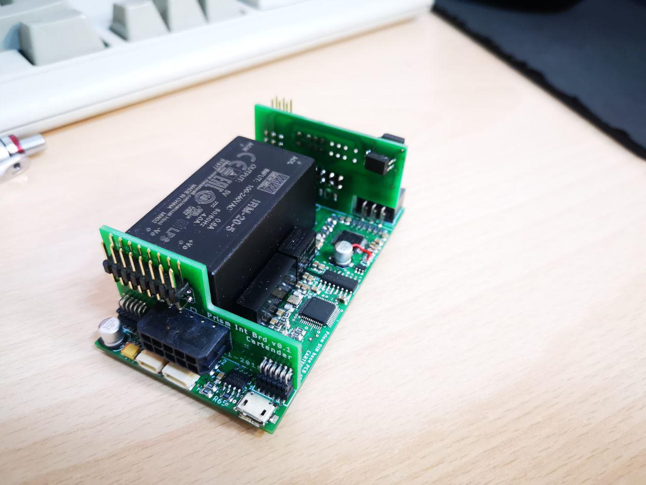
Everything fits nicely, and the only thing left to add is the Linux board. This design gives me a lot of flexibility, as I can easily replace the Linux module without having to mess around with other components. And owners can easily customize only this board, adding features like radio modules or other peripherals (i'm thinking about smartcards or TPMs for added security in critical applications). I started testing the concept with a GL-MT300N-V2 router, that is already marketed for makers - the product page proudly states "4 GPIOs for more DIY funs" as a selling point. The standard pin strips made it very easy to work with the board, and at that point I played around with the idea of using that router itself in the final product, so that everything's already working and certified:
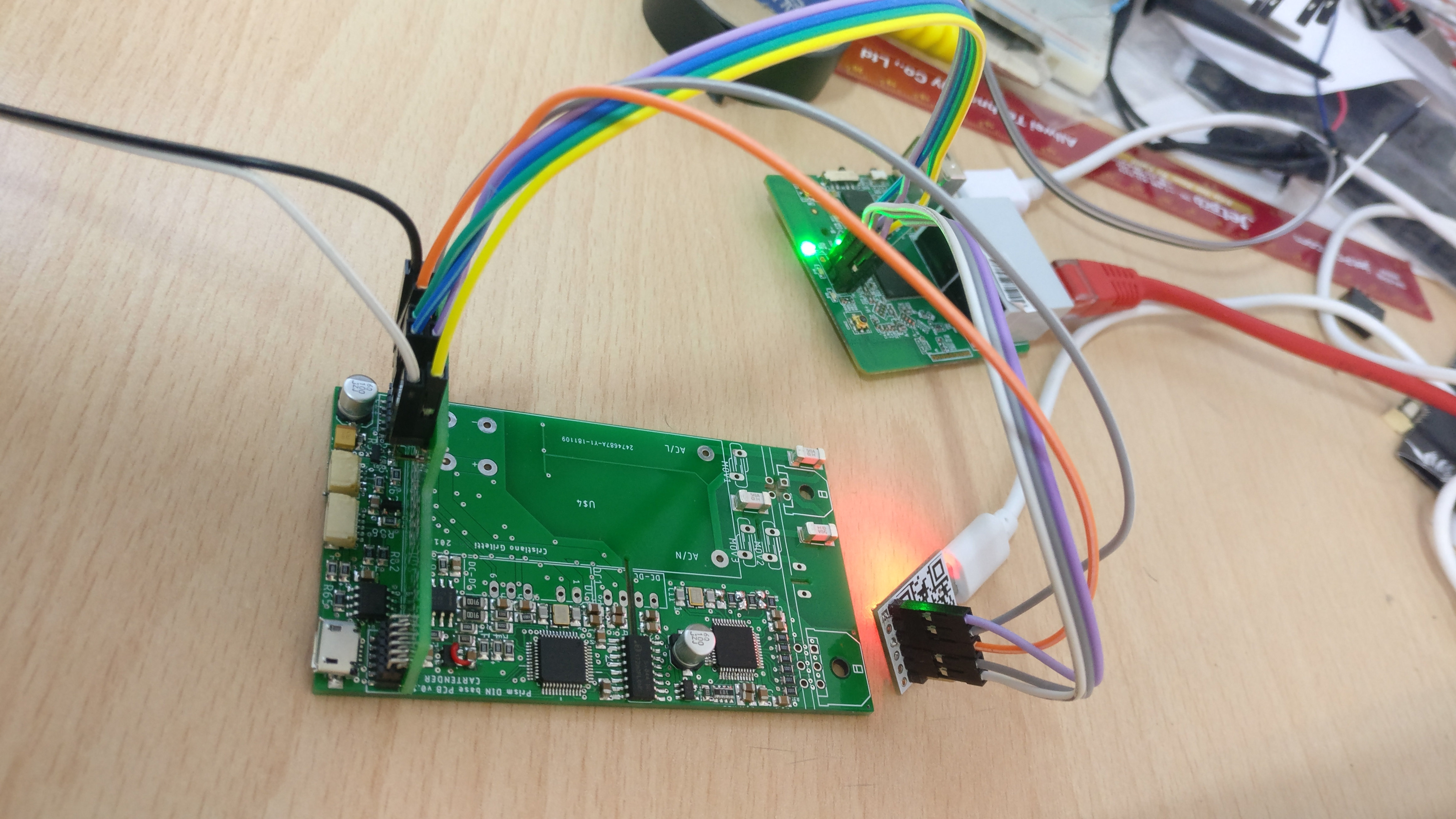 This would have been a bit expensive, also because I'd have to open up all the routers and mod them to add the serial port connection. So I decided to test some modules, and designed the first prototype to fit the SkyLabs SKW29, with a Mediatek MT7688AN chipset:
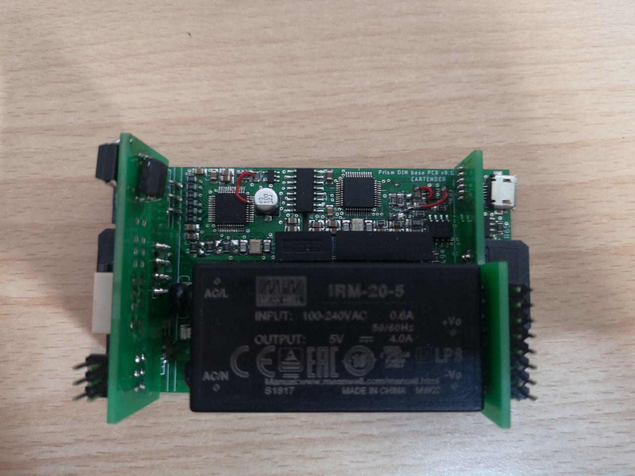
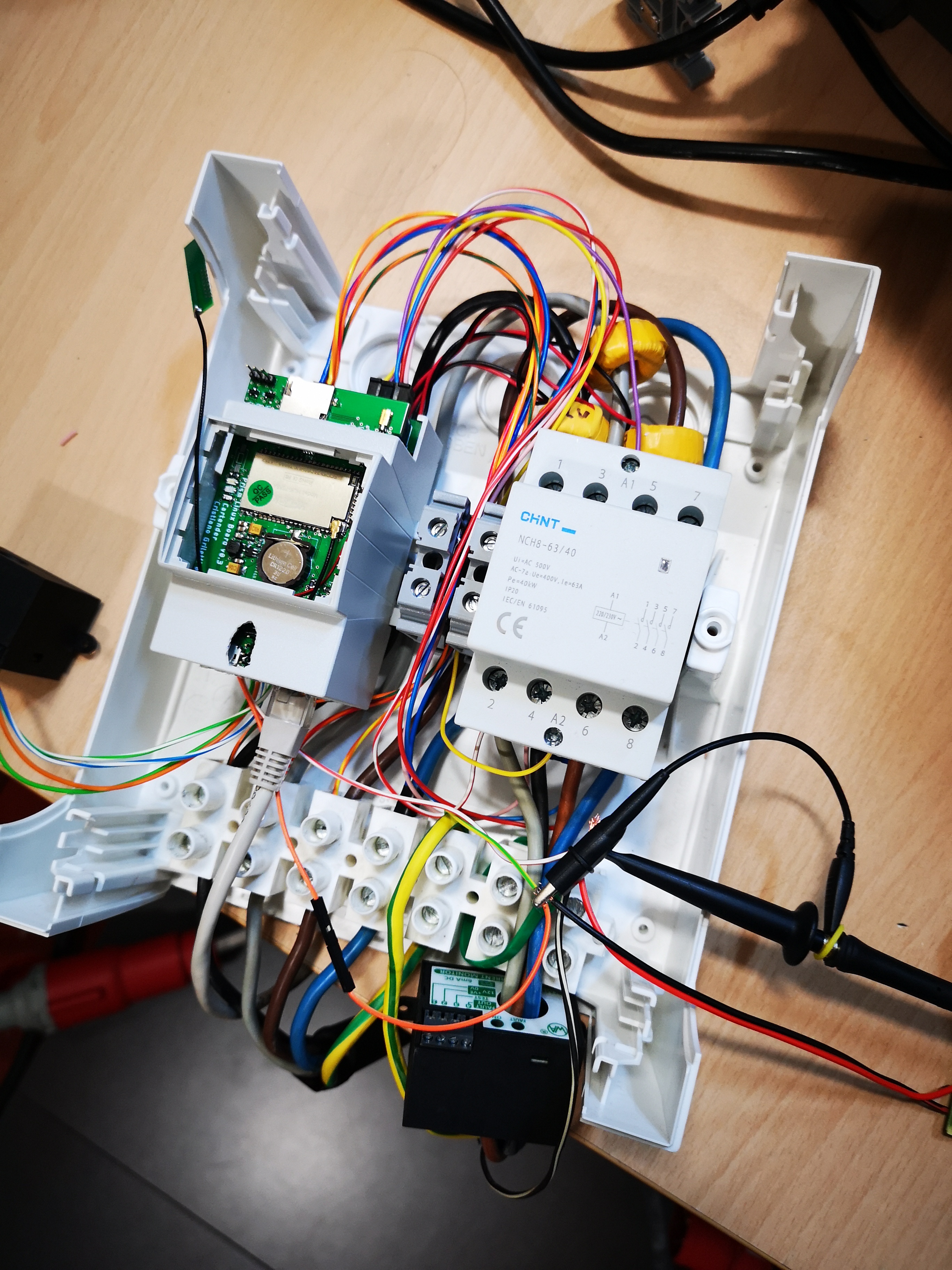
 I'm pretty proud to say that almost everything worked on the first prototype! Thoroughly testing every part of the circuit in advance paid off, and I had to fix only three bodge wires for a missing power connection and two inverted pins on the Pilot circuit. The boards did fit well inside the DIN box, that I completely cut away to better see the internal spaces.
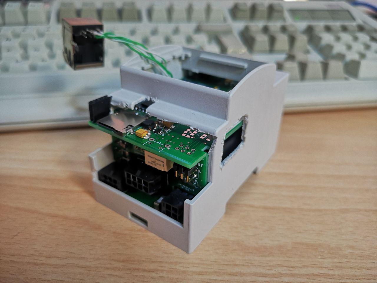
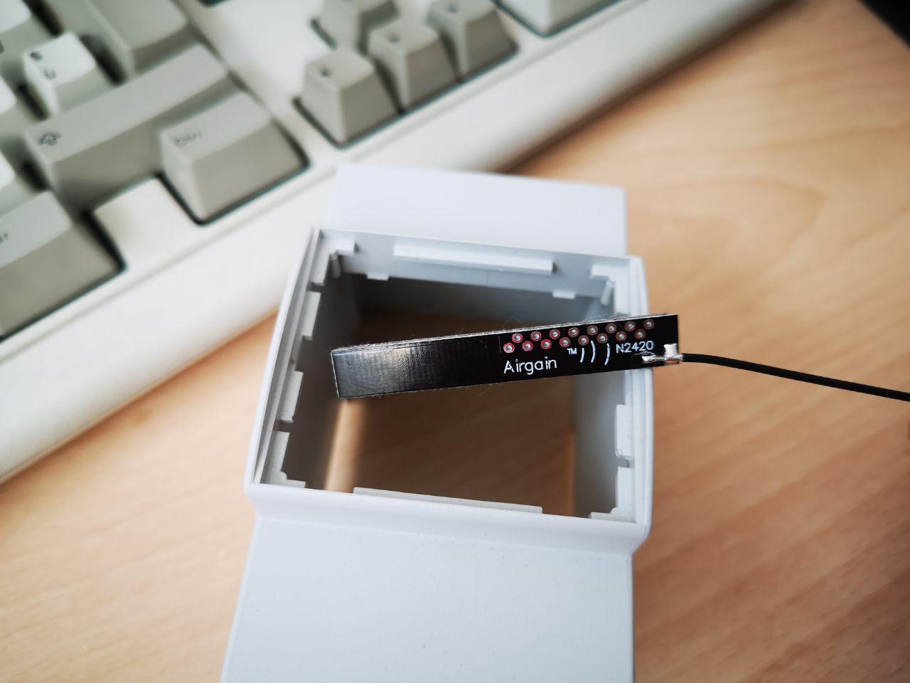
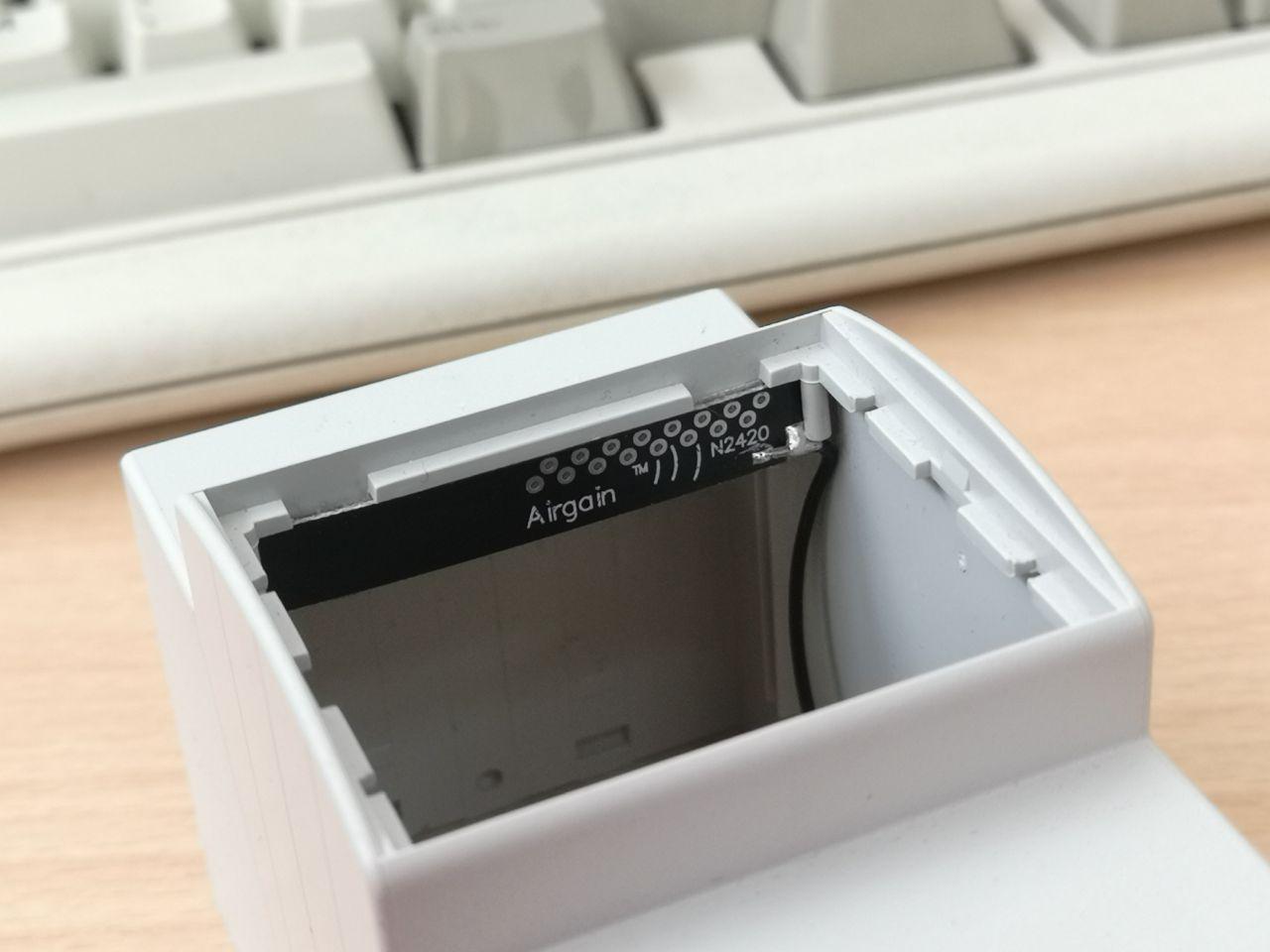
On a side note, the antenna I choose for the router module fits perfectly on the plastic slots inside the box:
While this prototype works great, there was still a lot of room for improvement, especially on the connectors selection. Molex MicroFit connectors are pretty expensive, and I'm using four of them; Samtec 90° fine pitched connectors are quite exotic and expensive too; the expansion connectors I used are too fine pitched and hard to manually crimp, and that would be ok for a commercial product but not for a DIY-oriented one (I made the same mistake on the 3310 WiFi project, but I didn't have other choices there due to space constraints).
The first improvement was to replace all the signal connectors with standard JST PHs, easy to crimp and widely available even with 2mm pin spacing. I kept the Molex MicroFits for the high voltage stuff, improving isolation on the PCB side with cutouts and protection resin, and decided to use only standard pin strips to connect the PCBs.
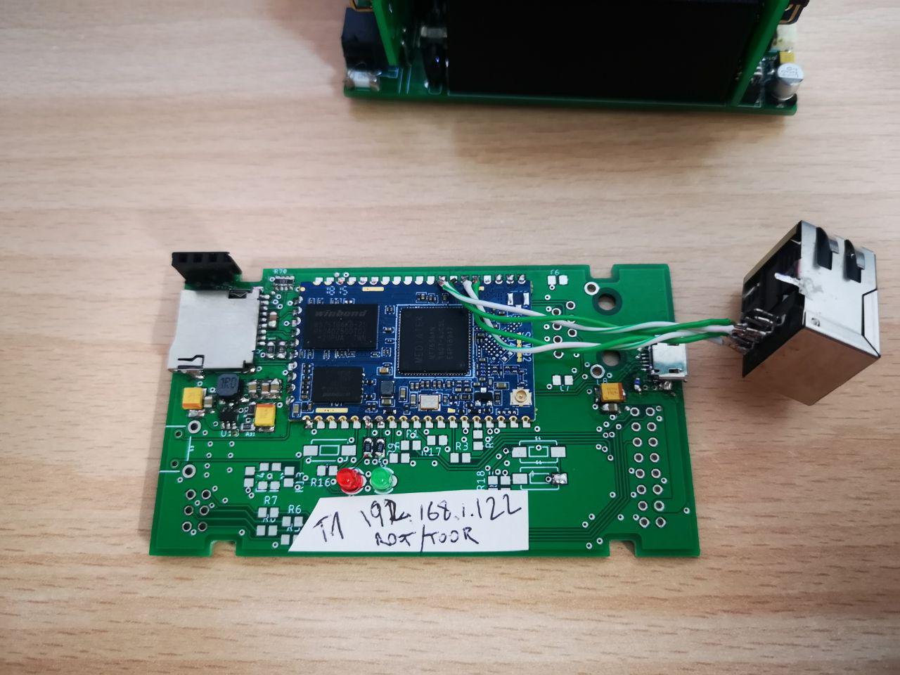
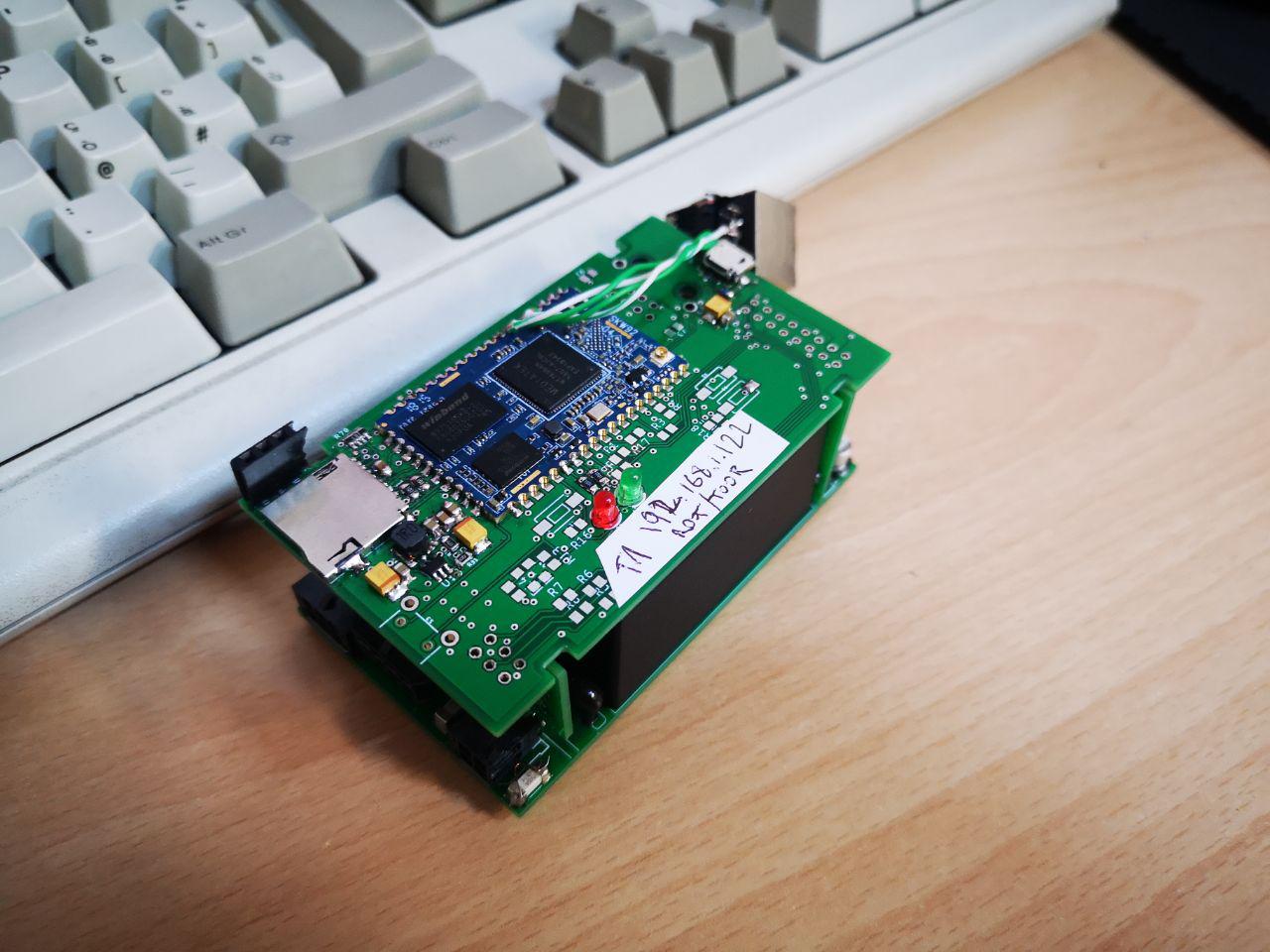
Since the HV and control electronics were pretty ironed out at this point, I started working on improvements for the Linux board. I moved from a SkyLabs SKW92 to a HiLink HLK-7688A module that is smaller, shielded and, it seemed, better supported. I also added a DS1307 RTC with its battery. Here it is:
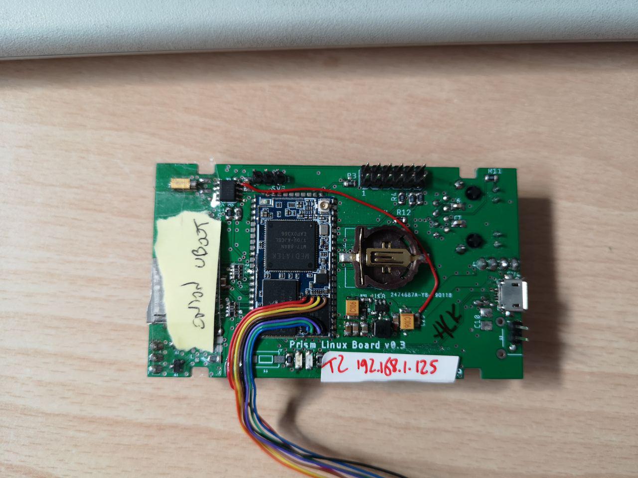
In that picture I removed the module shield because I was experimenting with UBOOT and of course I bricked the module many times in the process, so I had to solder wires to the flash to use an external programmer to restore the backups:
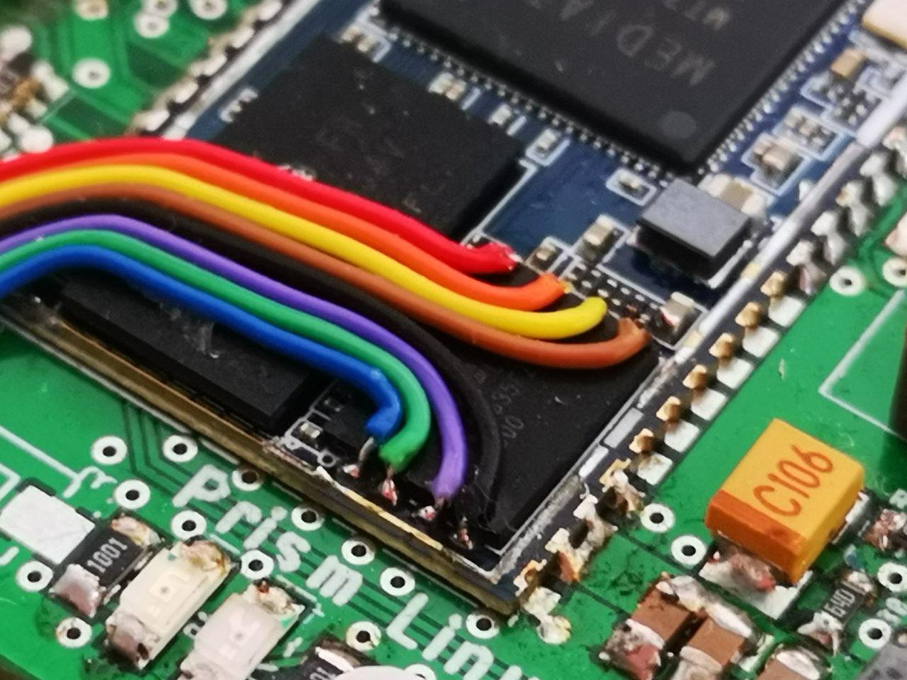
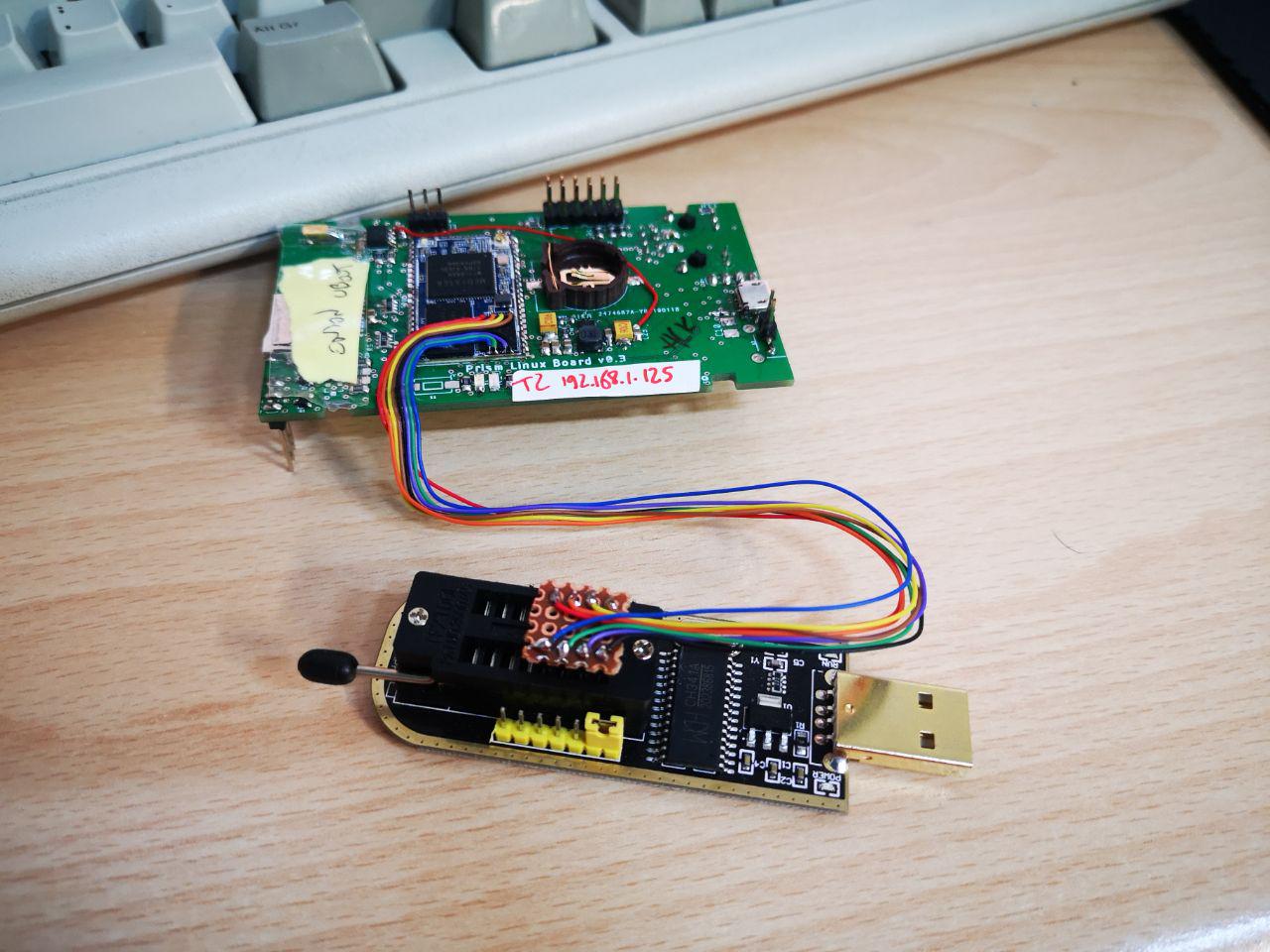 On that picture you can also see the red wire I used to fix the power problem I had with the RTC, supplying 5V instead of 3.3V.
And here it is, happily charging a car! :)
On that picture you can also see the red wire I used to fix the power problem I had with the RTC, supplying 5V instead of 3.3V.
And here it is, happily charging a car! :)
 I'm almost done designing the new revision of this part, but in the meanwhile you can find all the design files, the board templates for the enclosure and the cables diagrams on my github repo. The firmware for the base STM32 handling the charge process is here.
Discussions
Become a Hackaday.io Member
Create an account to leave a comment. Already have an account? Log In.