 Miroslav Zuzelka
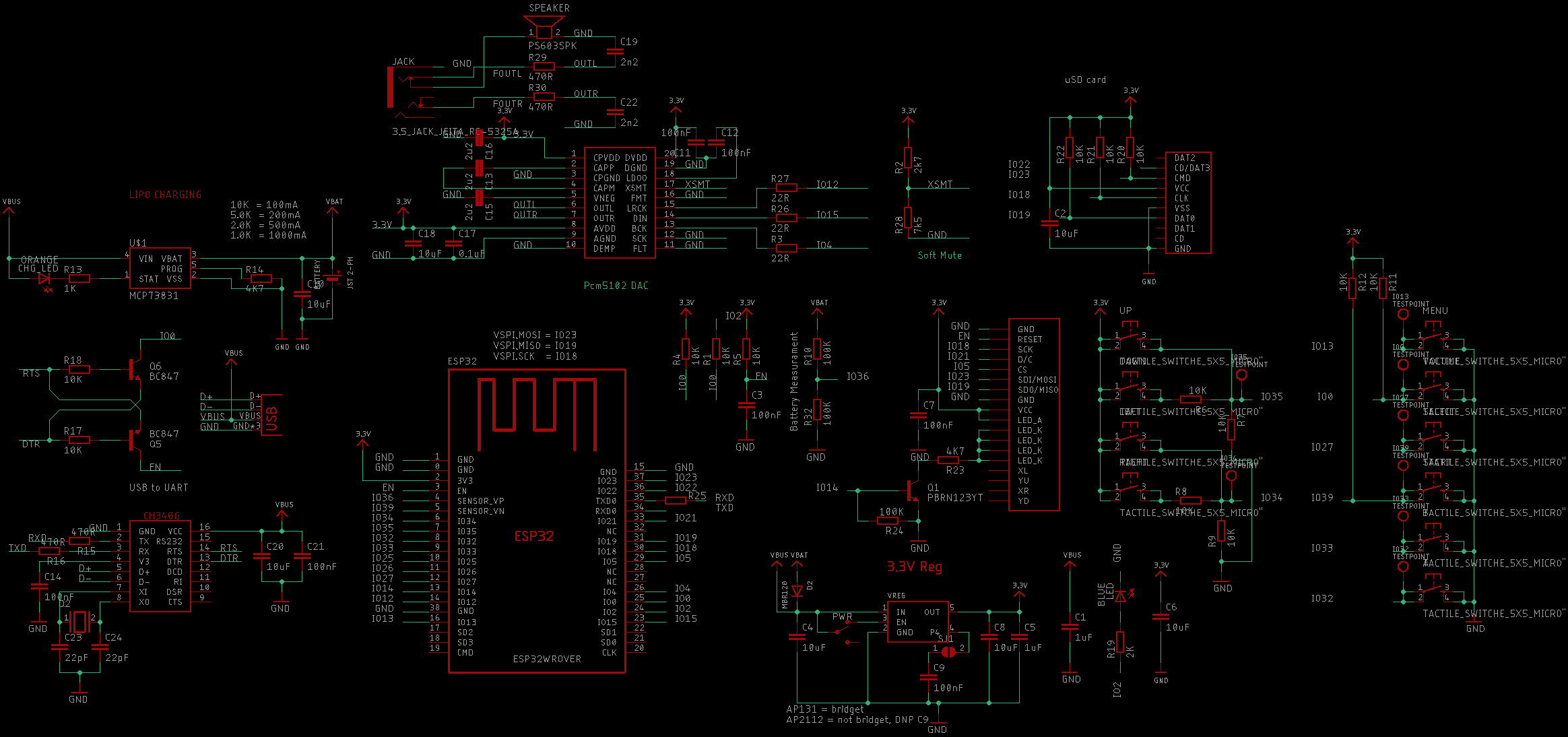
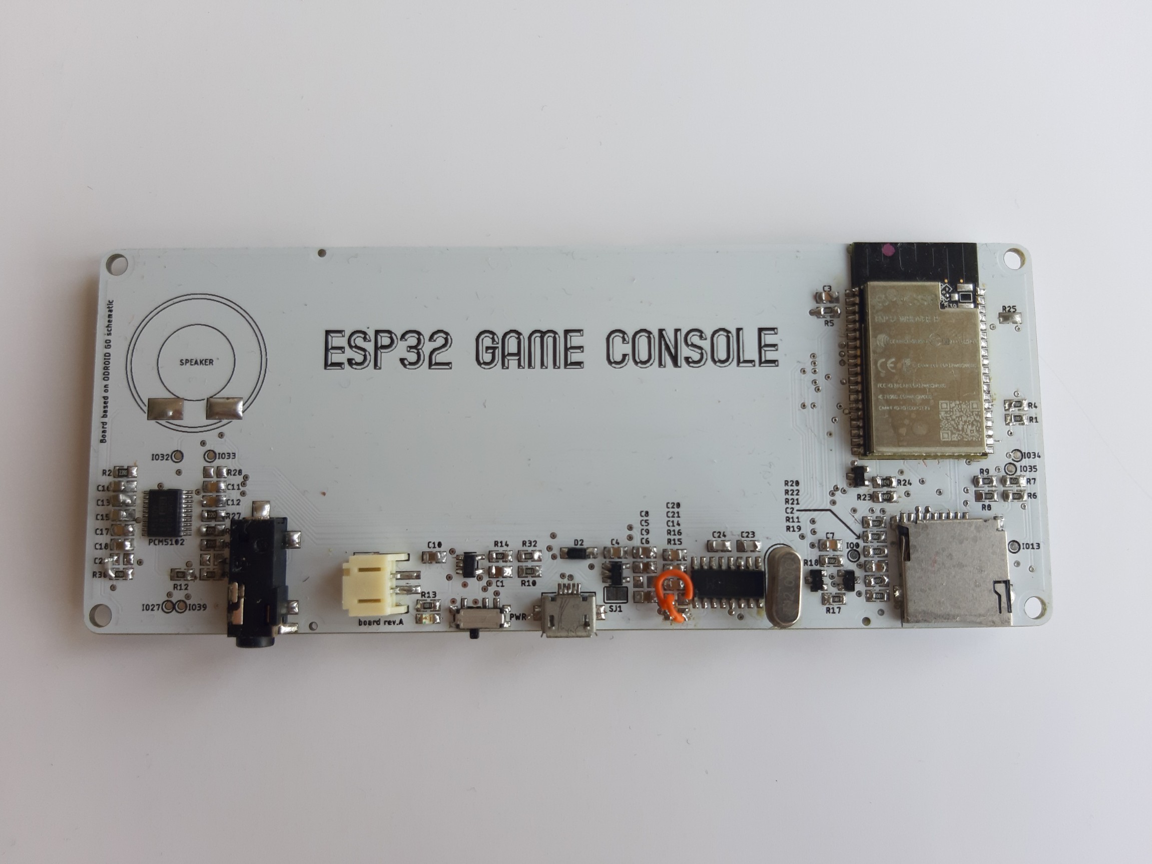
Now, when I gathered all information which I need, I can design PCB. My goal was to make this better than original piece and I did read somewhere that original sound is quite bad, I decide that I will not use original sound chip and I will upgrade it to PCM5102 which is I2S chip and it was already supported by original FW of the Odroid Go (OG).
Here is schematic:
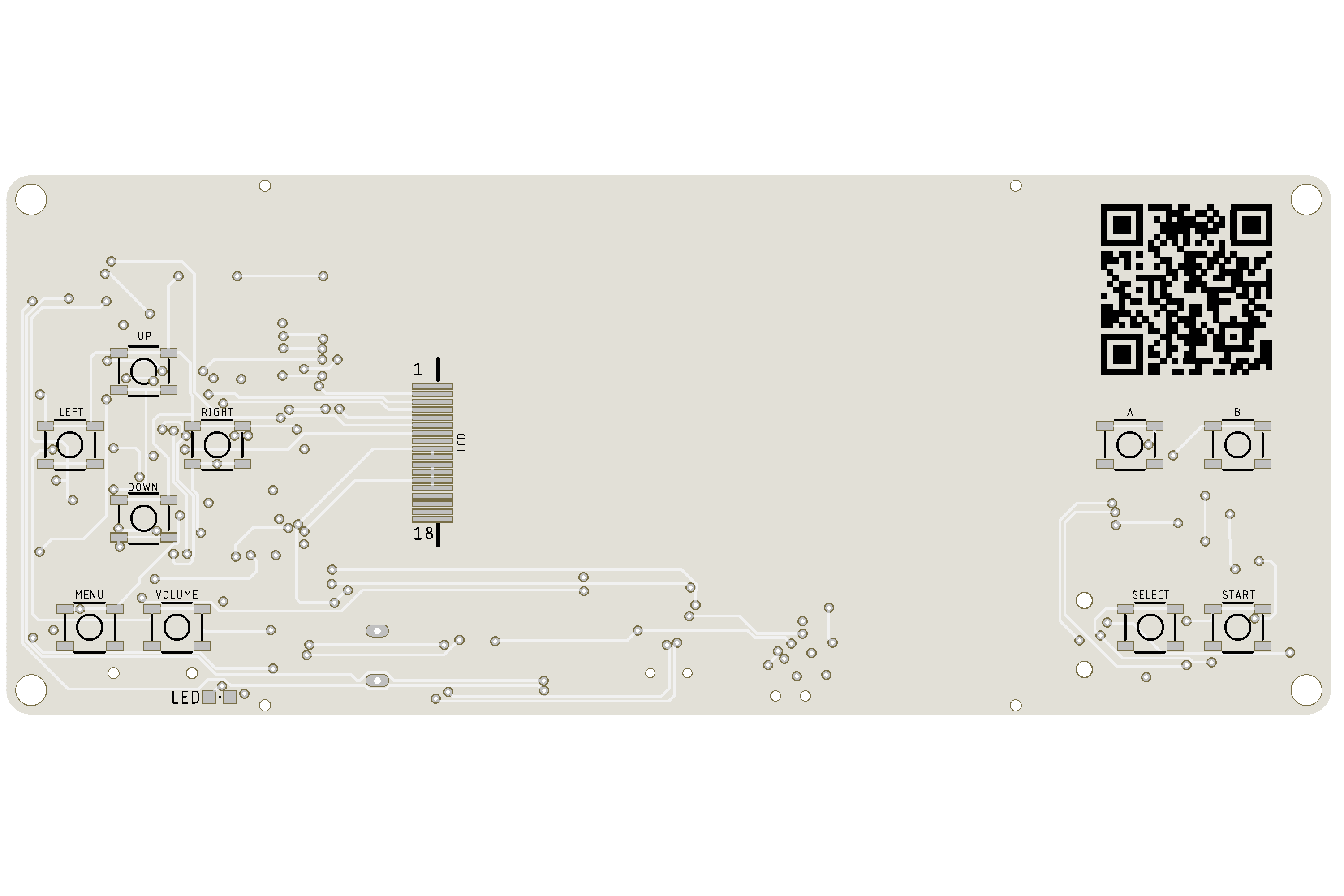
Routed board looks like this:
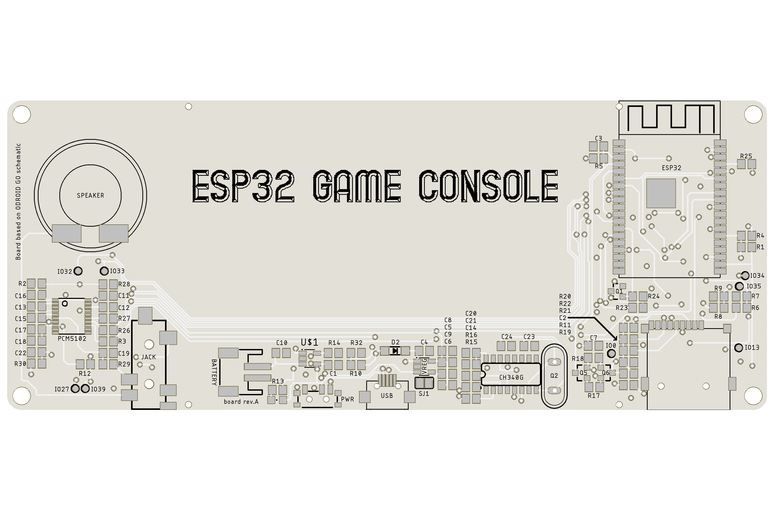
Because I had no SMD crystal at home, I used THT one. Speaker should be connected by wires directly to board.
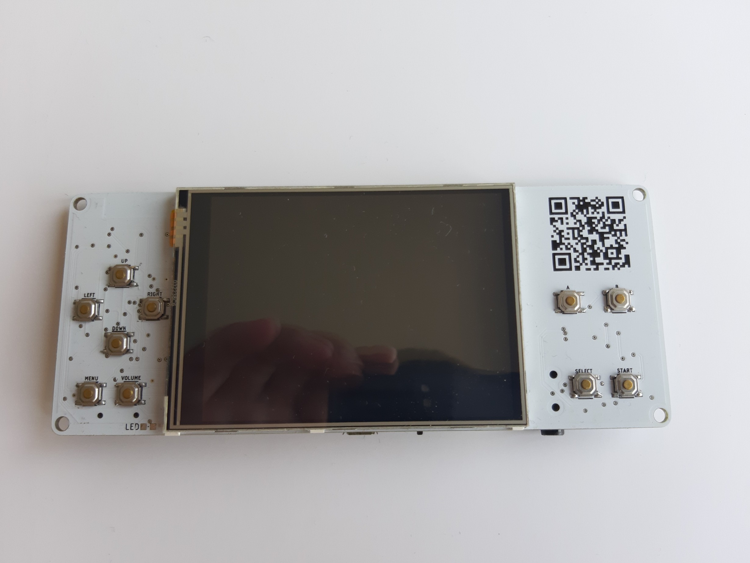
When boards arrived, I soldered one by hand with parts which I had at home. Because I did choose to use THT crystal and did not realized that I can not solder it through from bottom side, I had to solder it in standing position (can be seen on picture) so it is not sitting on the board.
Firstly I could not make USB converter work, but after some debugging I found out that my RX & TX lines are swapped so that was reason why I could not make it work. To repair this, I decide to sacrifice 2 pcs of 470 ohm resistor, which are on this connection and I cross these lines with wire. After that, I could programm ESP32 chip.
Next problem which I encounter was with the screen. I could see that there is some image, but I had no backlight. I measured voltages on LCD and those were fine. I also checked continuity on ground plane and that was also OK. When I was trying to find out where is the problem, I sometimes made it work for a second or two with my hands, which let me to conclusion that there will be really problem with ground somewhere. I looked at schematic where should be ground and bodged it with wire and this made it work. I could not regulate brightness, but I had backlight.
So I had working USB converter, ESP32, SD card, screen, charging circuit and last thing on the list was sound chip (because I had to order it). I solder it on the board, fire it up and all what I heard was ticking and buzzing noise and very very low sound coming from game. This was a big problem. I spent few hours by checking the Internet if I did something wrong but schematic was right. I also used osciloscope to look if there is right signal and when I selected I2S audio in FW of OG, I saw right signals at scope and none when I choose internal sound chip in FW. After few days of trying to solve this I did find out that I made mistake with plascing of the components and there are wrongly placed capacitors at the output signal. I desolder them and turned them by 90° and bodged them to resistors and I had working sound. At that point I was really relieved.
Here is final result:
I designed 3D printed case so anyone can print it in desired color and probably change it as well.
My friend Lubos Moravec made for me small intro video which you can see here:
I was happy that I made it work and more happy when people start to comment it at YT. Someone mentioned that he would be interested in one if it has conductive buttons and not those micro switches which make quite loud clicking noise.
Other thing which I realized was, that not all games support this I2S sound chip and that someone could end up with no sound in game.
I decide to resolve this in next version.
Discussions
Become a Hackaday.io Member
Create an account to leave a comment. Already have an account? Log In.