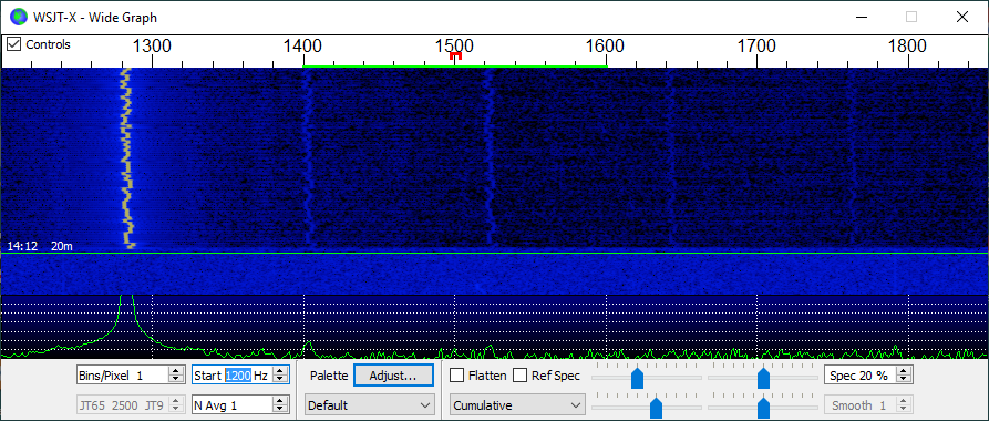
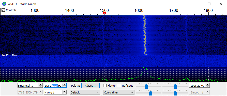
• Closing Thoughts

    ziggurat2909/01/2019 at 18:40 0 comments

    Summary

    Since the code and electronics are working now, I am considering work on this project to be complete (well, for the time being at least).  What follows are thoughts on follow-on projects and future directions.

    Deets

    This project began primarily as a testbed for my working with the Si5351A clock generator chip, and secondarily as an experiment in seeing if a WSPR encoder/modulator could be produced with the 'minimal system development board' (BluePill).  I did not intend to produce a stand-alone WSPR transmitter as an end in itself.  Given that, I consider this project completed, and now it's time to tear down the circuits so that they can be re-used in other things.  However, the experience has spurred some new thinking....

    Not Going to Make a PCB

    As mentioned, I don't intend to make a PCB for this stand-alone WSPR transmitter, however, along the way I got a small amount of exposure to KiCad.  I had been planning to investigate KiCad for years but had never gotten around to it.  When I actually was an EE decades ago I used a very quirky Swedish CAD called 'EE Designer III'.  It was written in compiled BASIC, lol!  (well, the graphics kernel was in something else).  Anyway, these days we have usable open-source options, and I liked that KiCad also does not have limitations.

    In this project, I had used it to drive a SPICE simulation of the low-pass filter for harmonics rejection

        Harmonics
    and I think they have a ways to go in their SPICE integration, but still it is somewhat serviceable -- maybe much more so with practice.

    Also, as part of testing 

        Acid Test
    I crufted together an HF-radio-to-PC interface so that I could use the 'official' decoder to prove my modulator.  This tangential mini-project is something that I need to have all the time, and in a robust enclosure, so I think I am going to try my hand at laying out a board for that stuff.  This board should be quite simple (maybe single-layer), so I think it is small enough a project to give me experience with creating symbols and using the tool from start to finish.

    Need to Do Further Work on Class E PA

    I attempted to make a class E power amplifier

        Power
    but it is quite inefficient, which rather takes away from the charm of class E.  I am pretty sure this is due to the driving of the switching MOSFETs, but I need to prove that.  The class E operation is interesting to me if I can get it live up to its potential because that would be more battery-friendly for a transmitter for use in the field.

    Switchable Band Filters

    In this project I punted on implementing multiband operation in the RF section, opting instead for single-band operation on 20 m (14 MHz).  The software and modulator work just fine on all the bands, but the harmonic output has to be corrected before hooking it to an antenna.  However, I'd still like to have one unit be able to transmit on all the bands without physically swapping out stuff.  Looking at commercial offerings, it seems that most multi-band filters operate simply by having a band of single band filters that are switched in and out -- often via relays.  I'm not personally fond of relays, but they do work.  I might try to make a multi-band filter bank using semiconductor switching, though.  I probably need to look into PIN diodes.  I don't know that I strictly need PIN diodes since the frequencies for the HF bands are pretty low, but nonetheless, this is an area of future investigation.  Plus I get to make more callouses on my fingers winding a bunch of toroids!

    Receiving WSPR

    Encoding and modulating WSPR is pretty easy:  do the transformations of the data to produce the 162 symbol stream and clock out the symbols as tones.  Very little RAM and CPU overhead are involved, and this is why the BluePill was more than sufficient for the task. ...

    Read more »

  • Power

    ziggurat2908/31/2019 at 23:20 0 comments

    Summary

    A simple class E power amplifier is produced to boost power output.

    Deets

    Originally, I thought I would require a power amplifier to make the transmitter work, but it turned out I could use it successfully with my antenna even with just the 12-ish milliwatts that comes directly out of the Si5351!  Even so,  now I was interested in producing a power amplifier stage, anyway.

    There are many kinds of amplifiers that are classified into, well, 'classes' -- 'A', 'B', 'AB', 'C', 'D', 'E', 'F', ....  The first few are more regular in that they refer to how much of the signal's phase is passed through the amplifier's linear region, with A being 360 degrees (basically, 'always'), and B being 180 degrees, class C being less than 180 degrees.  After that it is more or less just 'I came up with a new kind of amplifier' and it's not about conduction angles anymore.  Class D is basically filtered PWM, and class E is a specially-switched mode into a resonant load scheme.

    The motivation for these different schemes is of course that they have different properties.  Class A is 'linear' -- output is a reproduction of the inputs, but is also the least efficient (maximum theoretical 50%, real-world around 25%).  Class B is more efficient (maximum theoretical 78.5%), but is only half a cycle so often it is used in pairs for each half cycle.  There is a little point at the zero-crossing, though, where junction bias effects occur causing 'crossover distortion', so they aren't really used.  Rather a hybrid called the class AB is more commonly used which biases the two amplifiers in such a way as to nullify the crossover distortion.  Those amplifiers are used more in audio applications.

    Class C amplifiers output highly distorted signals (due to the short time spent in conduction), but have higher efficiency.  These are not used in audio applications but often are used in RF applications.  They work in RF because the signal integrity of the carrier is not important --that causes harmonics of the carrier that can be fixed up by filtering.  Rather the envelope and frequency/phase deviations are what are important, and those would be in the passband of such a filter.  The upside is that you get much greater efficiency (can be around 90%), and that is usually the overriding concern for both large transmitters emitting kilowatts or more or battery-operated transmitters.

    Class D is not used in RF and is meant for things like audio and motor control.  Class E is described in 1975:
      N. O. Sokal and A. D. Sokal, "Class E – A New Class of High-Efficiency Tuned Single-Ended Switching Power Amplifiers", IEEE Journal of Solid-State Circuits, vol. SC-10, pp. 168–176, June 1975.
    This class is specifically for RF use and involves a tuned output stage.

    Since the output filter I produced is already band-specific, and because the class E is (or can be under the right conditions) very efficient, and because I was curious, I decided to give class E a try.

    It's a switch-mode amplifier, so there must be a switching element.  I happen to have sacks of 2N7000's laying around, so maybe I can use some of those?  Additionally, they are MOSFETs, so they have a positive temperature coefficient of resistance.  That means you can parallel them to get extra capacity because the collection will naturally balance current amongst themselves.  (Bipolars have a negative temperature coefficient, so if one device were to take on slightly more load, it would get hotter, and then would take even more, and get still hotter, and...  thermal runaway.)

    I have plenty of toroids of various kinds on hand now, so at worst I should just need caps.

    An oft-cited presentation was made by David Cripe titled "Class E Power Amplifiers for QRP", which as best as I can tell was first published in:

      QRP Quarterly Vol 50 Number 3 Summer 2009, pp 32-37

    and later also at the...

    Read more »

  • Power Update

    ziggurat2908/27/2019 at 19:20 0 comments

    Summary

    It turns out that I did not strictly need the power amplifier after all.  Rather, I discovered that the synthesizer's frequency was off due to incorrect crystal loading, and other variances.  I altered the loading and provided a correction feature.  After getting the signal to be much more accurate, I am now able to transmit a weak signal that can be received by others without a power amplifier.  But I'm still going to make the power amplifier, anyway.

    Deets

    I was making some minor enhancements and bugfixes and verifying that this didn't cause any regressions in functionality.  That meant verifying that the modulation still worked, and I was doing that by receiving signal leakage with my HF radio and using the WSJT-X to decode it.  However, for whatever reason I didn't really notice this on the WSJT waterfall display before, but my signal was off quite a bit; in fact it was off to where it was well outside the 200 Hz passband for the WSPR signals.  So it had no business being decoded at all.  But I also noticed multiple weaker images of my main signal periodically spaced.  I had noticed before that sometimes I would get decoded twice, and suspected some sort of harmonics being involved, though I really only expected harmonics from the square wave output of the synthesizer, and those images would be far, far away from this band.

    (Incidentally, the green line between 1400 and 1600 is the 200 Hz WSPR band, and the little red box under 1500 is the center sub-band -- numbered '16' in my scheme.  Also, I find if you change the 'N Avg 1' to '1' from the default of '3', then you can make out the WSPR bits as the FSK.)

    The WSJT-X waterfall display lacks many features -- I wish there was a 'cursor' feature that would at least tell you the frequency over which you hover, and preferably the magnitude of the signal, but I suppose this display is not meant to be taken too seriously and so there's not a ton of effort that goes into it's implementation.  At any rate, guestimating the spacings from the display, it looked like 120 Hz.  I.e., twice the mains frequency (here), or what you'd expect if the power were full wave rectified somehow.  Fiddling with the 'band' feature, I was able to manually keep one or two of those harmonic images in the 200 Hz window, and was able to confirm that the presence of two harmonic images in the passband did cause two decodes, and when just one was there, then only one decode happened (my software by default hops around the passband randomly transmission-to-transmission).  When I had two in the passband I was also able to confirm the 120 Hz spacing because WSJT-X reports the center frequency of the decoded signals.  My guess is that some sort of power supply hum is coupled into the unit and is causing a mixer interaction with the synthesized signal, thereby causing these images.  The project is quite a kludge in its present form!

    <<XXX images -57 dbc image>>

    The first concern was the fact that my intended signal was so far off from the mark.  I vaguely remembered that there was a register for specifying the crystal loading capacitance, and confirmed that the software was not setting it at all.  The default is 10 pF.  Breakout boards such as these from China are typically short on specifications,, but I noticed the Ada Fruit boards mention setting it to 8 pF.  I added some code for that, and my main signal moved, but now just above the passband; lol!

    So maybe I need 8.75 pF?  Well, that's not an option.  I imagine there is perhaps still not a perfect loading of the crystal, and that there are perhaps some other basic variances.  I added in some code to provide a compensation factor.  It's just a constant parts-per-million value that is saved with the persistent settings and used when computing the values for the main PLL.  I added a new persistent setting and some code in the command...

    Read more »

  • Harmonics

    ziggurat2908/25/2019 at 18:54 4 comments

    Summary

    The output of the Si5351A is a square wave, which contains too much harmonic content.  A filter is constructed.

    Deets

    The Si5351A puts out a square wave -- after all it is supposed to be a clock generator.  However the square wave has too much harmonic content to be legal, so it is necessary to filter those out.  It was my desire to make some sort of tunable filter so that the project can operate on all the bands out-of-box, but after some research I decided that would be an undertaking nearly a project in itself.  So in the interest of moving the project forward I punted and decided to build the filter just for the 20 meter band (14 - 14.350 MHz).  The rest of the project will work on all bands under software control, but the final output stage is tuned to a specific band, and needs to be swapped-out for other bands.

    Having simplified that aspect of the project, I did a little research on filters and came across this document:

    http://www.gqrp.com/harmonic_filters.pdf
    harmonic_filters.pdf
    Revd. George Dobbs G3RJV

    which is a delightfully written, cookbook form discussion of a lowpass filter design for common ham applications like this.  The design is worked-through for all the amateur bands, and is suitable for up to 10 Watts (which is plenty more than is needed here).  Additionally, the author took the pains to fiddle with component values to get the desired characteristics out of standard-valued components rather than, say, 164 pF, etc.  So for most practical applications you just need to get the parts and build it.

    Some of the parts are toroidal inductors that you must wind yourself.  I found this site to be invaluable:
    http://toroids.info/
    You can select your core and enter the desired inductance and find out how many turns and approximately how long of wire you will need.  The same folks also sell the various toroids, and I got 100 of the T37-6 ones that I needed, figuring I would be making more filters in the future, anyway.  The prices were generally quite reasonable, and the cores arrived just a few days later.

    For those that don't already know, when winding a toroid, a 'turn' is considered a pass of the wire _through_the_center_ -- i.e. not counting windings on the outside.  Also, consistency in winding direction can be important (not here), and it seems the convention is to wind 'clockwise'.  I.e., if you hold the toroid in your left hand, you pass the first turn starting from the top most surface, on the left side, passing down through the center.  Then you pull the wire up and around the outside and then and pass down through for the next turn.  Each of these turns proceeds forth advancing around the toroid in a clockwise direction, so the last turn will exit on the right side from the bottom.  So, start from about 7 o'clock and end up about 5 o'clock.  Neatness counts a little, though generally not critically.  It's worth trying to keep the wire more or less tight against the core, and it's worth spreading the windings evenly.  But if you run out of toroid and have a few bunched windings to get the correct number of turns, this is not the end-of-the-world -- it will still work fine.

    I needed to get capacitors, too, which were more expensive than I would have expected, but I wound up getting ceramics with a NP0/C0G dielectric for about 6-7 cents each (when you order 100).  I got these from Mouser, so here are the part numbers for reference:

    https://www.mouser.com/ProductDetail/810-FG18C0G1H181JNT0
    https://www.mouser.com/ProductDetail/810-FG28C0G1H391JNT0

    I got 100 because of the way the price breaks, and I'm going to have to pay shipping on this anyway, so why not just buy a whole bunch more for a couple bucks and amortize that shipping against future projects that might need these parts?

    While waiting for toroids and capacitors, I decided to play a little...

    Read more »

  • Acid Test

    ziggurat2908/23/2019 at 16:44 0 comments

    Summary

    The project was tested against a 'real' radio and digital interface into a PC running the WSJT-X software.  It was verified to have modulated the WSPR signals correctly.

    Deets

    We're veritably at the end-of-the-road of implementing software for the WSPR beacon, save bug fixes or usability enhancements.  We need to verify if it works.  I don't want to actually put it on the air because it might not be working.

    What I decided to do was use my HF radio (an IC-756PROiii) with the WSJT-X program from the creators of the digital mode.  However, the radio just down-converts signal to AF; there needs to be something else that gets in into the computer.  (I know that some of the newer radios have this interface built-in, but mine does not.)  The most common way of doing this is via the sound card.

    I didn't want to tie up my regular sound card, but I had some years ago bought a cheap USB one.  They still make them, they are called '3D Sound Adapter'.  (I don't know why it is called '3D', because it just has a standard stereo plug.)  I had been planning to do this for a while now, so I did a little mini-project of building this adapter.  The gist is to adapt the 'sound card' via an attenuator to a pair of isolation transformers, which are then connected to the radio's 'Accessory' port.

    I kludged this together:

    The transformers can be had from Mouser for $2 each, or you can go for China for $0.40 each if you are willing to buy ten and wait (as I did).  Use eBay to search for this item:

        "Audio Transformers 600:600 Ohm Europe 1:1 EI14 Isolation Transformer"
    and you'll probably find it.

    The sound device can be found on eBay as well if you search this item:
        "USB 3d Audio Sound Card Microphone Headset Adapter"
    These run about $2-4 depending.  The shell is easily separated so you can solder wires and not mess with the jack.

    You tweak the trimmers to give a signal that doesn't cause clipping.  Incidentally, the 20 K pot I used for the Mic input is a log taper.  Both trimmers wound up being OK-ish in their mid positions, so not much tweaking was actually required.  I suspect that I could just measure and not use trimmers for a 'production' unit, but I'm not sure.  Maybe they should even be regular pots...

    One other thing I also used was a Computer Aided Tuning (CAT) cable.  This allows the computer to set the dial frequency and do other stuff, like key the transmitter (this saved me some circuitry, I originally planned to make a VOX-like PTT feature, hence the larger perfboard than required).  If you search eBay for this item:
        "USB CI-V CAT Cable For ICOM CT-17 IC-275 IC-756Pro Shortwave Radio"
    you should be able to find one for about $10.  It's nothing more than a USB-to-serial adapter, so if you have some of those lying around (and you should!) then you can whip one up with ease.  I don't know the details, but I'm sure the web abounds with info.  I prefer the FTDI parts, but my cable had a CH-340 and it works just fine.

    Having stuck all that stuff together, and having configured WSJT-X to receive WSPR from folks around me, it was now time to try it out.  But what for an antenna?  Well, it turns out that I didn't need an antenna for this test.  My open board project spewed out enough stray radiation that my nearby radio was easily able to pick it up without a proper antenna.

    The signal was decoded successfully.  I feel confident now that the software works, and the signal modulation is correct.  Now I have to go analog and get it on the air.  There are some things to consider, though:  is there enough power, and is the signal clean enough to be legal?  The first question is 'maybe', and the second is 'no'.  The output of the synthesizer is a square wave and as such has far too much harmonic content to be legal.

    Next

    Filtering harmonics

  • Synthesis and Modulation

    ziggurat2908/21/2019 at 16:52 0 comments

    Summary

    Finally, it is time to fiddle with the Si5351A (the original motivation for this project; lol).  I look at some libraries and wind up more or less winging it.

    Deets

    Now that all the pieces are in place and presumably working, it's finally time to make the synthesizer chip do its thing.  The Si5351 is conceptually simple:
    • a clock source; this variant uses an external crystal, though others support an external clock or a VCXO
    • there are two main PLLs
    • there are a bunch of 'multi synths', which are fractional dividers, one per output
    • this device has three outputs; others have 8

    The goal is to create program the PLL to generate some high frequency from the input clock source, and then use the 'MultiSynth' to divided it down to your desired output frequency.  This scheme can support output from 2.5 KHz to 200 MHz.  There is one MultiSynth per output, so that is conceptually straightforward, but the MultiSynths can be connected to either of two PLLs.  Since there is not one PLL per output, different outputs will need to share PLLs, so you have to do a little planning to figure out what that common PLL should be producing in order to satisfy all the MultiSynths to which it is connected.

    If you're not familiar with a PLL, it's a control system wherein the goal is to maintain zero phase difference between two inputs.  The output is proportional to the phase difference (and subject to various internal filtering to get the response as desired).  That output is typically fed into a variable frequency oscillator that serves as one of those inputs, and in this way the oscillator's frequency is made to track the input frequency (and moreover be in-phase).  This sounds kind of boring in itself, but it gets interesting when you put frequency dividers in the loop.  By dividing the variable frequency oscillator by some factor, say 'M' before putting it into the the input, then that oscillator will need to be made to operate at M times the external input frequency.  This is how you can 'synthesize' various frequencies from a single input frequency.  You can put dividers at various other points in the system as well to provide more options.  It's very much like designing an amplifier with an op-amp:  there you use voltage dividers and a differential amplifier to be able to generate the desired voltage transformation, and here you use frequency dividers and a phase detector to be able to generate the desired frequency transformation.

    This device has 188 registers that have to be programed to make it produce useful output.  That's an exaggeration because many of those registers are repeated (for the various multisynths), and this part only has three outputs -- not eight -- so the set is smaller than that absolute maximum.  But it is still quite bewildering coming from your core goal of 'I would like to produce frequency X on output Y'.  There is no frequency register per se.

    But when you consider that this part was created "for replacing crystals, crystal oscillators, VCXOs, phase-locked loops (PLLs), and fanout buffers in cost-sensitive applications", then the design is a little more understandable.  The intended use-case involves using a separate desktop tool as a 'wizard' to grind through all the possibilities and come up with a solution comprising a list of registers and the value to which they should be set.  You then simply blindly program those values into the chip (and you can burn them into OTP memory so that the chip will come up in that configuration).  If you're using the chip as a replacement for multiple crystals in an integrated system, then this is plausible.  But we're using it in a way perhaps not as intended and need to alter the output frequencies on a frequent basis at runtime.

    As a quicky, I did pre-compute the four FSK tones for the 20 m band and added routines to set the output to those values.  This was more for...

    Read more »

  • Encoding WSPRs

    ziggurat2908/19/2019 at 17:46 0 comments

    Summary

    A utility module that encodes the data into the WSPR format for transmission was produced.

    Deets

    The WSPR system is for reporting weak signals (hence the name) which implies a low signal-to-noise ratio.  That also implies a lot of distortion that can (will) render a signal hopelessly lost in that noise.  The scheme Joe Taylor (K1JT) and Steve Franke (K9AN) used here in WSPR is 'Forward Error Correction' (FEC).  And if there's such a thing as 'forward' error correction, there aught to also be a 'backwards' error correction -- and there is.  Backwards (or 'reverse') is very easy to understand:  you detect errors and ask the sender to send things again.  Forward is much more involved, and avoids that back communications channel.  There are many applications where you simply can't have a reverse channel, and that's one place that FEC shines.  It was particularly popular in deep space probes, but now it's used all over the place.  The gist is that you add redundancy in a careful way such that you can not only detect errors, but with a maximized degree of certainty deduce what are the erroneous bits and change them to what they should have been.  That's the 'forward' part:  the extra stuff is sent forward along with the message and the receiver can figure it out for itself without having to ask for a retransmission.

    There's many different schemes of FEC, and although 'convolutional coding' is used in WSPR, many of the other modes in the family of things Joe Taylor use other ones.  Joe Taylor himself has mentioned on several occasions that the evolution of these protocols was partially motivated by his fascination with communications technology and the desire to familiarize himself with the various states of the art.  It's not clear to me whether the choice to use convolutional coding here was motivated by it's technical merits relative to other choices, or whether this was more the way the wind was blowing at the time of inception.  (He had previously used Reed-Solomon in JT65, and later used LDPC in FT4.)

    While researching, I came across a document that described the mechanics of the WSPR encoding process in plainer English than the original source:

    G4JNT, “Non-normative specification of WSPR protocol”,
    http://www.g4jnt.com/Coding/WSPR_Coding_Process.pdf

    I won't repeat it except as a high-level summary with my own commentary.  The steps are:

    1. condition the data
        The conditioning step is to do sanity checking and some cleanup of the data prior to encoding.  The callsign has to be placed correctly in it's buffer (the third character must be a digit, padding as needed to ensure this), the maidenhead locator has some restrictions (e.g. the first two characters must be upper case and 'A' - 'R', the others digital), and the power level has to end in the digits 0, 3, or 7.  These numbers correspond to 1x, 2x, and 5x power levels.
    2. pack the data
        Some simple arithmetic encoding is done to use as few bits as possible for each datum.  This can be viewed as a manual form a data compression.  The conditioned callsign gets encoded into 28 bits, the locator gets encoded into 15 bits, and the power is encoded into 7.  (Power is a bit special in that the high bit is always set, and I don't know why this is -- otherwise it could have been encoded into 6 bits.)  This results in 50 bits of message data.  Then 31 bits of zero are padded out to 81 bits.  (I don't really know why the zero-padding is needed; my guess is it is to pick up the tail end of the system's convolution.  There are implicitly 31 zeros in the front as well, but it doesn't require padding to realize their effect.)
    3. transform the data using a convolutional code
        The data stream are fed into a convolutional encoder.  This use well-known polynomials discussed in:
        W. Layland, James & A. Lushbaugh, Warren. (1971). A Flexible...
    Read more »

  • Implementing the WSPR Task (skeleton)

    ziggurat2908/17/2019 at 15:27 0 comments

    Summary

    The WSPR task skeleton is implemented.  This goes through all the motions of scheduling transmissions, shifting out bits at the correct rate, and some other things like re-encoding the message when GPS is locked and syncing the on-chip RTC witht he GPS time.

    Deets

    For the WSPR activity, I define another FreeRTOS task.  This will be the last one!  The task will run a state machine, cranking out the bits of the WSPR message on a scheduled basis.  It will be driven by two on-chip resources:  the Real Time Clock (RTC), and a timer (TIM4).  The RTC will be used for it's 'alarm' feature to schedule the start of a transmission at the start of an even-numbered minute, as required by the WSPR protocol.  The TIM4 will be used to pace the bits we send.  The WSPR protocol requires the bits to be sent at 1.464 Hz, or about 0.6827 bps.  I assigned some other duties to the WSPR task, such as keeping the RTC synced when GPS lock comes in.

    CubeMX Changes for RTC and TIM4

    The RTC is used to kick off a WSPR transmission when an even numbered minute begins.  The on-chip RTC has an 'alarm' capability that can be used to generate an interrupt at the designated time.  You will need to open CubeMX, and ensure that under the NVIC settings for the Timers, RTC, that the following is enabled:

        RTC alarm interrupt through EXTI line 17

    The RTC interrupt works by way of a weak symbol callback function.  You simply define your own 'HAL_RTC_AlarmAEventCallback()' and that is sufficient for you to hook into the interrupt handler.  I put mine in main.c, since CubeMX likes to put things like this there, but that is not required.  The implementation is to simply forward the call into the WSPR task implementation by calling WSPR_RTC_Alarm(), which is exposed in the header 'task_wspr.h'.

    While that kicks of the start of the transmission, the subsequent bits are shifted out under the control of a general purpose timer which also can generate an interrupt when the configured period expires.  In this case I am using TIM4, and under it's NVIC settings in CubeMX you need to ensure that the following is enabled:

        TIM4 global interrupt

    While in CubeMX, we need to also set some values for TIM4 so that the interrupts come at the correct rate.  The timers are driven by the CPU clock.  We have configured to run at the maximum speed of 72 MHz, so we need to divide that down to 0.6827 Hz.  That means dividing down by 49,154,400.  The timers have a 16-bit prescaler and then also a 16-bit period, so we need to find a product of these two that will work out to be pretty close to that number.  I chose a prescaler of 4096, and a period of 12000, which works out to be 49,152,000 and that is close enough.

    You set those values in CubeMX by subtracting 1 from each of them.  This is because 0 counts as dividing by 1.  So the prescaler will be 4095 and the period will be 11999.

    Set those values and regenerate the project.  This will cause the init code to have changed appropriately.  Do not forget to re-apply the fixups that are in the #fixup directory!

    The Timer interrupts work somewhat the same, but there is one for all the timers, and it already exists down in main.c because we configured TIM2 to be the system tick timer.  We just add to that implementation in the user block:

    void HAL_TIM_PeriodElapsedCallback(TIM_HandleTypeDef *htim)
    {
      /* USER CODE BEGIN Callback 0 */
    
      /* USER CODE END Callback 0 */
      if (htim->Instance == TIM2) {
        HAL_IncTick();
      }
      /* USER CODE BEGIN Callback 1 */
    
    	else if (htim->Instance == TIM4)
    	{
    		//we use TIM4 for WSPR bit pacing
    		WSPR_Timer_Timeout();
    	}
    
      /* USER CODE END Callback 1 */
    }

    ISR Code

    So, we have two methods WSPR_RTC_Alarm() and WSPR_Timer_Timeout() that are exposed by the task.wspr.h and implemented therein.  I generally avoid doing significant work in an Interrupt Service...

    Read more »

  • Haque in a Flash

    ziggurat2908/15/2019 at 15:06 1 comment

    Summary

    The STM32F103C8 on the BluePill (and really I guess every board using that part) is rumoured to have 128KiB flash, despite the datasheet's claims otherwise.  I lightly hacked the project to test this theory out.  It seems to work!

    Deets

    The datasheets indicate that the STM32F103x8 has 64KiB flash and the STM32F103xB has 128KiB flash.  Otherwise, they have the same capability.  The chips do identify themselves over the SWD interface, and mine definitely reports itself as the 'C8, and not the 'CB (plus, the part markings).  However, I read somewhere (alas, can't cite, but apparently this is well-known) that it seems that STMicroelectronics opted for some economies and these parts actually the same die, and in fact both devices have 128KiB flash!  If you think about how much it costs to set up a production line, it starts to make sense how this saves them money -- there's no extra cost for the silicon, but there's a lot of extra cost for the tooling.  They probably do a final programming step during qualification that fixes the identity.  Fortunately, it seems that this doesn't actually inhibit access to that extra 64 KiB.  Here is how I hacked my build system to enable its use.

    Hacking OpenOCD

    The System Workbench toolchain embeds OpenOCD to operate the debugger/programmer.  This tool uses a bunch of config files that describe the chip's capabilities.  There are two locations which have configs for this chip:

    C:\Ac6\SystemWorkbench\plugins\fr.ac6.mcu.debug_2.5.0.201904120827\resources\openocd\scripts\target
    C:\Ac6\SystemWorkbench\plugins\fr.ac6.mcu.debug_2.5.0.201904120827\resources\openocd\st_scripts\target

    The 'fr.ac6.mcu.debug_2.5.0.201904120827' is quite possibly different on your system because it involves the version number that you deployed.  But you can figure that part out for yourself.

    In each of those locations is a file:

    stm32f1x.cfg

    I renamed this to 'stm32f1x.cfg.orig' and made a new copy named 'stm32f1x.cfg' which I hacked.  If you scroll down a ways, there is a part '# flash size will be probed' that is where we make a change:

    # flash size will be probed
    set _FLASHNAME $_CHIPNAME.flash
    #HHH I hacked the size to 128k
    flash bank $_FLASHNAME stm32f1x 0x08000000 0x20000 0 0 $_TARGETNAME

    So we are simply not probing, but rather explicitly telling the tool that we have 0x20000 (128 Ki) of flash.

    I went ahead and modded both copies of 'stm32f1x.cfg', however it appears that the operative one is the one that is in the 'openocd\st_scripts\target' location.

    Fair warning:  if you later download an update of the system, you will probably need to re-apply this hack, because new copies of files will be deployed.  You'll know if this happens though, because things will break (if you're using the high memory).

    Hacking the Build Config

    Next, we need to tell the linker about the flash.  This is done in the root of the project, in 'STM32F103C8Tx_FLASH.ld'.  Near the start of that file is explicitly stated the size of the RAM and Flash.  I changed it to this:

    /* Specify the memory areas */
    MEMORY
    {
    RAM (xrw)      : ORIGIN = 0x20000000, LENGTH = 20K
    /* HHH I hacked the size */
    FLASH (rx)      : ORIGIN = 0x8000000, LENGTH = 128K
    }

    My project build now is well below the 64 KiB barrier, but I modded the persistent settings file to specify the last page of the 128 KiB instead of the same for the 64 KiB.  This made it easy to prove that stuff can be stored there.

    //HHH I modded this to get 128K #define FLASH_SETTINGS_END_ADDR 0x08010000
    #define FLASH_SETTINGS_END_ADDR 0x08020000

    Then I did a clean and rebuilt.  I started the debugger, and you will see along the way a message:

    Info : device id = 0x20036410
    Info : ignoring flash probed value, using configured bank size
    Info : flash size = 128kbytes

    So it's on.

    I connected to the monitor, and persisted settings.  Then I connected with 'STM32 ST-LINK Utility'.  This will think there is 64...

    Read more »

  • Flash (♫ Ah-ah ♫)

    ziggurat2908/13/2019 at 19:59 3 comments

    Summary

    Where we left off, the flash consumption was 63588 bytes, leaving us perilously close to the 64 KiB mark.  By ditching some large standard library code and manually implementing workalikes, we reclaim a lot (about 16 K) of space and get the project back on-track.

    Deets

    A while back when implementing some parts of the GPS task (parsing the NMEA GPRMC sentence) and parts of the monitor (printing and reading the persistent settings, and printing the GPS data), we used sscanf() and sprintf() to make that task easier.  Moreover, because we needed floating point support we introduced some linker flags to enable that capability.  Helpful as these functions are, they are notoriously large in their implementation (indeed this is why the default 'no float support' exists in the first place).  Time to drop a few pounds.

    I spent an unnecessarily long period of time with this research, but I wanted to prove the point to myself.  First I took out all the major modules, then added them back in incrementally to see their local impact.  It proved what I already suspected about the scanf() and printf().  But a simpler test was really all that was needed, and I'll summarize those results here for the curious.

    First, as a baseline, here is the flash usage with full support that we require:
    63588; baseline

    Then, I incrementally removed the '-u _printf_float' and '-u _scanf_float' options to see their respective impacts, and then effectively removed the sscanf() and sprintf() altogether using a '#define sscanf (void)' and '#define sprintf (void)' hacks to see the effect of their removal.  I built afresh each time and collected the sizes:

    with scanf() no float, and printf() with float:
    57076; cost of scanf float support = 6512

    with scanf() no float, and printf() no float:
    50552; cost of printf float support = 6524

    removing scanf(), but leaving in printf():
    48388; cost of scanf = 2164

    removing both scanf() and printf()
    45644; cost of printf = 2744

    So, total scanf = 8676 and total printf = 9268, and total scanf/printf float cost = 17944.

    So if I replace those things with an alternative implementation, I probably will save a big hunk of flash that I can use for further code development.  Hopefully the replacements will not be nearly as large.

    First, I removed the dependency on scanf by implementing an atof() style function of my own concoction.  Internally this needed an atoi() which I also implemented and exposed.  This reduced the flash size considerably, to 55144.  So, from 63588 to 55144 is 8444 bytes.  If we assume the scanf() number above of 8676, that means my manual implementation incurs 232, so that is already quite nice.

    Next, I removed the dependency on printf by implementing an ftoa() style function as well.  This implied I needed an itoa().  The stdlib's itoa() is not that bad -- about 500 or so bytes, but I went ahead and made my own because it was helpful to alter the API slightly to return the end pointer for parsing.  Additionally, this stdlib has no strrev(), so I implemented one of those, too.  (I found it easier to shift out digits into the text buffer in reverse, and then reverse them when finished when the required length was known).

    That resulted in a build size of 46948, which is a further reduction of 8796 bytes.  If we assumed the printf() number above of 9628, then that means that my manual implementation incurs 1072 bytes.

    Thus the overall savings with the manual implementations is 63588 - 46948 = 16640 bytes.  That is likely enough to keep the project in business for the upcoming implementations, which include the WSPR task, the WSPR encoder, and the Si5351 'driver'.

    There was an unexpected bonus in this operation.  Apparently the scanf() and printf() functions use a lot of stack, as well.  I exercised my GPS and Command processor code to a great extent, and I can now safely revert to a 512 byte stack...

    Read more »