 ziggurat29
Summary
A simple class E power amplifier is produced to boost power output.
Deets
Originally, I thought I would require a power amplifier to make the transmitter work, but it turned out I could use it successfully with my antenna even with just the 12-ish milliwatts that comes directly out of the Si5351! Even so, now I was interested in producing a power amplifier stage, anyway.
There are many kinds of amplifiers that are classified into, well, 'classes' -- 'A', 'B', 'AB', 'C', 'D', 'E', 'F', .... The first few are more regular in that they refer to how much of the signal's phase is passed through the amplifier's linear region, with A being 360 degrees (basically, 'always'), and B being 180 degrees, class C being less than 180 degrees. After that it is more or less just 'I came up with a new kind of amplifier' and it's not about conduction angles anymore. Class D is basically filtered PWM, and class E is a specially-switched mode into a resonant load scheme.
The motivation for these different schemes is of course that they have different properties. Class A is 'linear' -- output is a reproduction of the inputs, but is also the least efficient (maximum theoretical 50%, real-world around 25%). Class B is more efficient (maximum theoretical 78.5%), but is only half a cycle so often it is used in pairs for each half cycle. There is a little point at the zero-crossing, though, where junction bias effects occur causing 'crossover distortion', so they aren't really used. Rather a hybrid called the class AB is more commonly used which biases the two amplifiers in such a way as to nullify the crossover distortion. Those amplifiers are used more in audio applications.
Class C amplifiers output highly distorted signals (due to the short time spent in conduction), but have higher efficiency. These are not used in audio applications but often are used in RF applications. They work in RF because the signal integrity of the carrier is not important --that causes harmonics of the carrier that can be fixed up by filtering. Rather the envelope and frequency/phase deviations are what are important, and those would be in the passband of such a filter. The upside is that you get much greater efficiency (can be around 90%), and that is usually the overriding concern for both large transmitters emitting kilowatts or more or battery-operated transmitters.
Class D is not used in RF and is meant for things like audio and motor control. Class E is described in 1975:
N. O. Sokal and A. D. Sokal, "Class E – A New Class of High-Efficiency Tuned Single-Ended Switching Power Amplifiers", IEEE Journal of Solid-State Circuits, vol. SC-10, pp. 168–176, June 1975.
This class is specifically for RF use and involves a tuned output stage.
Since the output filter I produced is already band-specific, and because the class E is (or can be under the right conditions) very efficient, and because I was curious, I decided to give class E a try.
It's a switch-mode amplifier, so there must be a switching element. I happen to have sacks of 2N7000's laying around, so maybe I can use some of those? Additionally, they are MOSFETs, so they have a positive temperature coefficient of resistance. That means you can parallel them to get extra capacity because the collection will naturally balance current amongst themselves. (Bipolars have a negative temperature coefficient, so if one device were to take on slightly more load, it would get hotter, and then would take even more, and get still hotter, and... thermal runaway.)
I have plenty of toroids of various kinds on hand now, so at worst I should just need caps.
An oft-cited presentation was made by David Cripe titled "Class E Power Amplifiers for QRP", which as best as I can tell was first published in:
QRP Quarterly Vol 50 Number 3 Summer 2009, pp 32-37
and later also at the ARRL Midwest Division Convention & Summerfest 2011, August 5-7, Cedar Rapids, Iowa on Saturday, August 6th. There are also various spreadsheet design tools that can be found on the Internet that distill the advice from that presentation; e.g.:
Class E Power Amp Design Using NMØS Equations
It's a handy tool, although it has a different output stage, and I had already created my lowpass filter for harmonics, so I simply did an impedance transform from the Class E to the existing filter using an autotransformer on an FT50-43 toroid with 6 and 4 turns. This translates the 18 ohms from the amplifier section to 50 ohms for the filter section. 18 * ((6+4)/6) ^ 2 = 50.
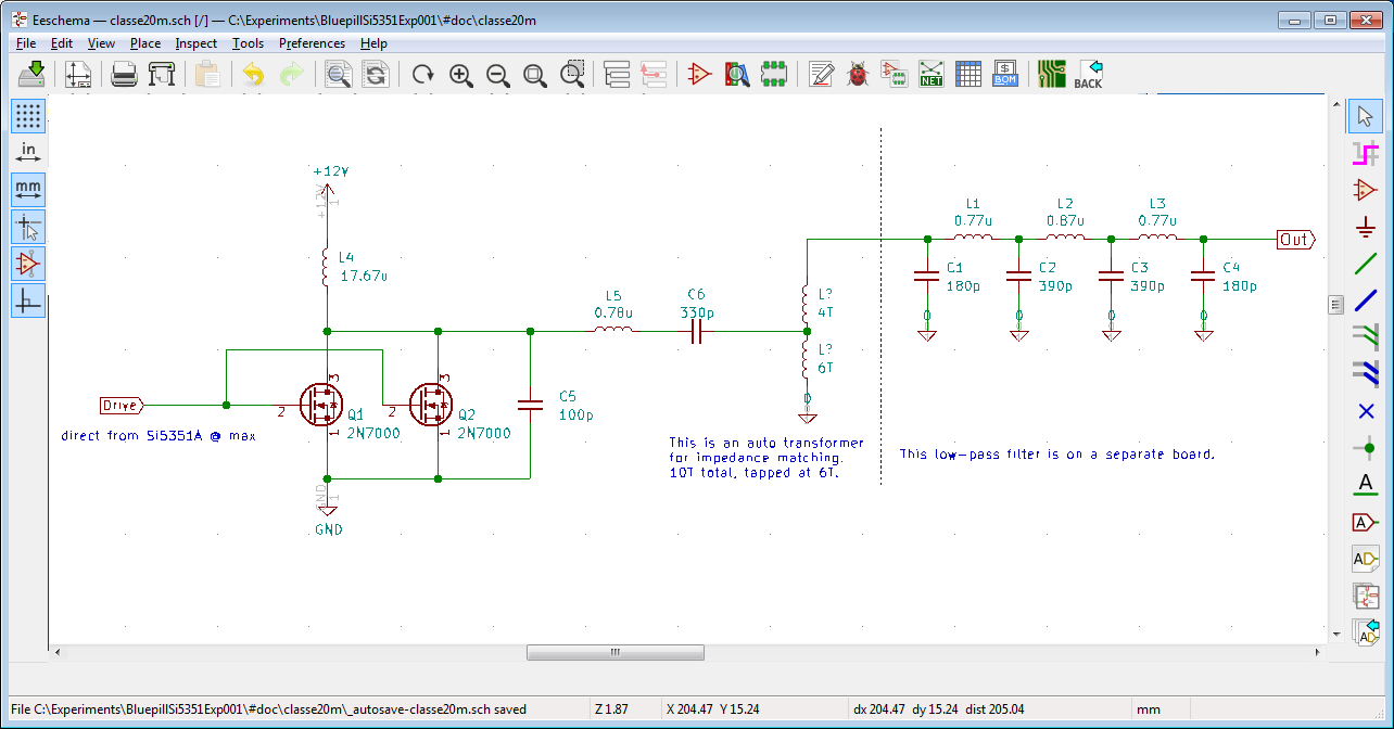
One complication of this design is the output power is a fixed, designed-in, aspect. I wanted to design for 2.5 W, which seemed about the maximum I could get out of ganging two 2N7000's in the class E configuration, but I had to decide on a power source. The rest of the circuit is powered from USB, so 5 V (though really 3.3 V via regulator), but 2.5 W / 5 V = 500 mA, and that's not considering losses or the rest of the circuit's consumption, so I didn't really want to put that on USB or on the switching transistors. So I bit the bullet and used a second 12 V power supply to relax that constraint a bit. I figure that the project in its current form is a breadboard implementation, anyway, and that if I were to redo it for 'production', I could either run it off 4 18650's or something like that and anyway I'd probably be rethinking this output stage, anyway. So in the interest of moving forward, I'm going with the kludge of a separate wall-wart for the power amplifier section. It might even burn itself up.
So out came more perfboards and whatnot:
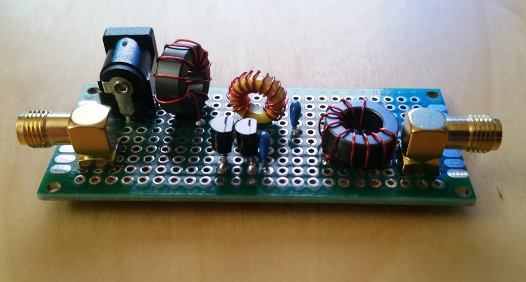
I couldn't decide on how to drive the 2N7000 MOSFETs, so I left a little space in front of them but for now just drove them directly from the Si5351A's output.
I hooked it up and terminated the antenna port and started to take some measurements. First, I left the power amplifier unpowered. This should make it obvious the effects of the capacitance load of the two 2N7000's on the Si5351A:
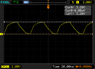
This does not look very good. The Si5351A just doesn't have enough drive for the capacitive load, so the transistors are probably going to be 'on' for longer than desired. This will have a bad effect on efficiency.
Powering on the amplifier (hope I don't burn it out! good thing I have a sack full!), the gate signal looks like:
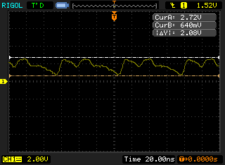
Blick! Ooooh! Those transistors are getting hot! Hot != efficient, so I'm definitely not in proper class-e operation, but since nothing has burned up yet, I'll keep moving. Looking at the drain voltage:
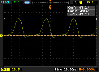
The shape of the waveform looks about like what one would expect, so it's doing something. 43V p-p, so the switch mode boost aspect of it is doing something, even if not ideally in this case.
The output of the amplifier goes through a series-resonant filter, the output of which then feeds into an impedance transformer to the output harmonics filter:

Almost sine-y. Then after the filter and into the dummy load:
Now it's looking a bit cleaner.
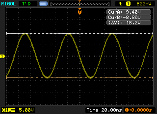
As mentioned, this is operating very inefficiently, though, which rather takes a bit away from the charm of 'class-e'. But, eager to see what happens nonetheless, I remove the dummy load (after it cools off! It's just a little SMA 50-ohm terminator -- probably 2 W max) and replace it with an adaptor to hook to the real antenna.
18.2 vpp = 9.1 vp = 6.43 vrms ** 2 / 50 ohm = 828 mw = 29 dbm, so I'll just call it 30, and put that in the settings for the system.
Running it for about 10-15 minutes shows spots up to 2900 km away:

So the power amplifier works sort of, but just enough not to self-destruct, so I consider that a practical fail. Later I'll look into fixing it up a bit. I'm pretty sure I need to drive those MOSFETs better, and it is possible that I might need even to do some tuning -- the whole point is that the switching is done at just the right time to minimize losses. But for the moment, it is working well enough to move on to other things.
Next
Teardown and closing thoughts
Discussions
Become a Hackaday.io Member
Create an account to leave a comment. Already have an account? Log In.