 Krists
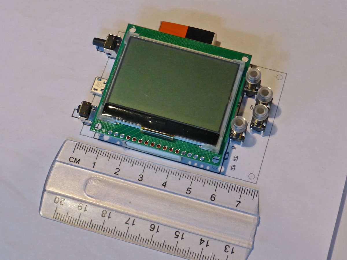
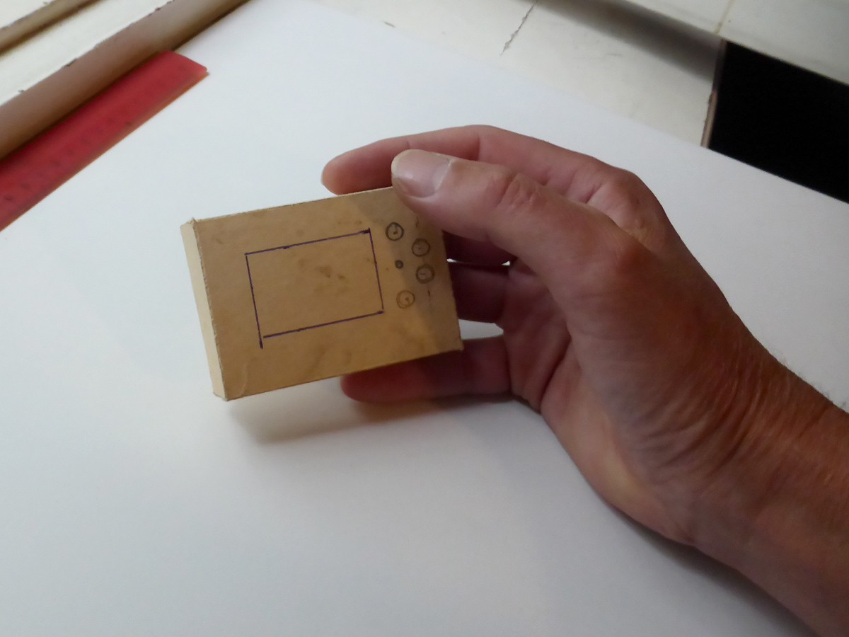
Having schematic seemingly working on breadboard it was time to move on to PCB. This required some decision on layout and controls for the device. Controls would be power on button, recessed firmware upgrade mode button next to USB connector and four controls next to LCD. One for starting and stopping data logging, other for changing trigger period and two more for up down for navigation where necessary. Main PCB would hold all elements and connector for LCD with its own PCB on top. Pig tail cable to serial port of muiltimeter would go on back of main PCB. With controls besides screen this sets form factor for device. Device would stand vertically on bottom edge. It seems that main controls might be operated single handed.
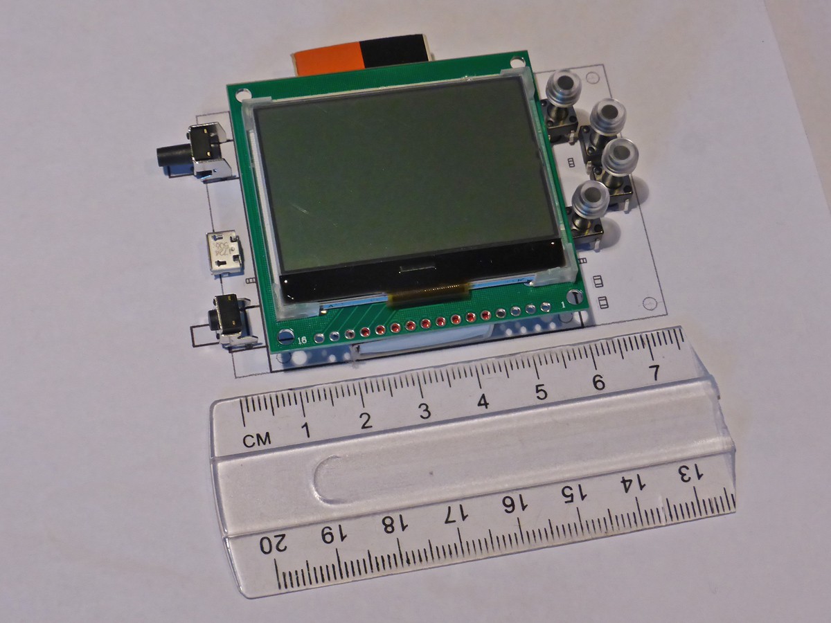
I opted for standard tact switches with silicone like material caps I sourced from eBay. Enclosure around this layout could be designed and 3D printed. Although it would be great to have front panel overlay it adds to expense and is separate part.
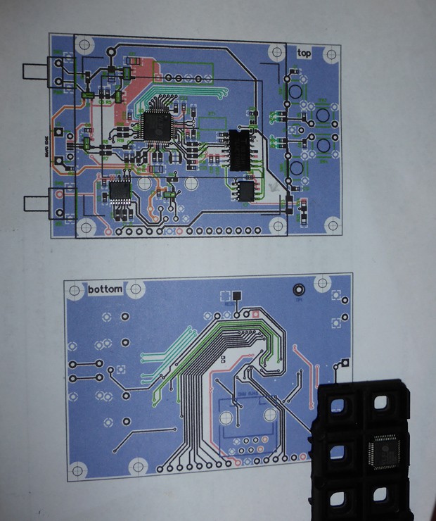
Initial version of PCB layout is complete, time will show if it has any flaws. Such PCB can as well be factory assembled with through-hole components soldered on later. Switches can be replaced with surface mount versions for later layouts. Everything will be done by hand soldering now.
Discussions
Become a Hackaday.io Member
Create an account to leave a comment. Already have an account? Log In.