Close
0%
0%

Tek V2

Version 2 of PS/2 keyboard adapter for Zeddies

Similar projects worth following
This project simplified provides quick and dirty matrix keyboard emulator to complement ZX-80/81 and ZX Spectrum boards

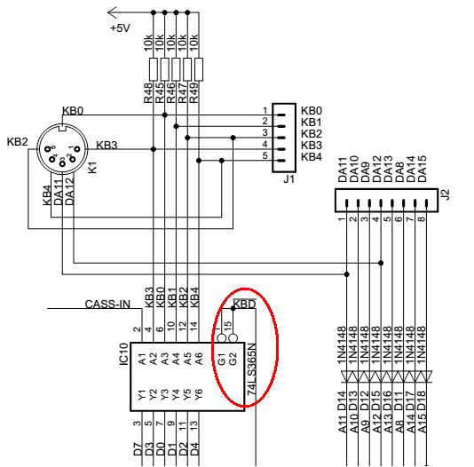
The ZX machines read the matrix keyboard by lowering 1 out of 8 upper address lines (A8..A15) and then read 5 bits of data in lines D0..D4 (as D5..D7 serve for other purposes).

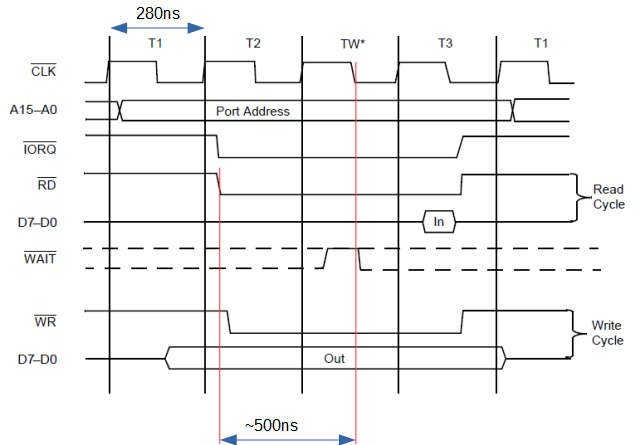
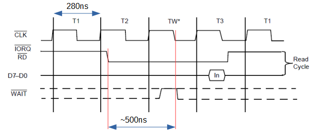
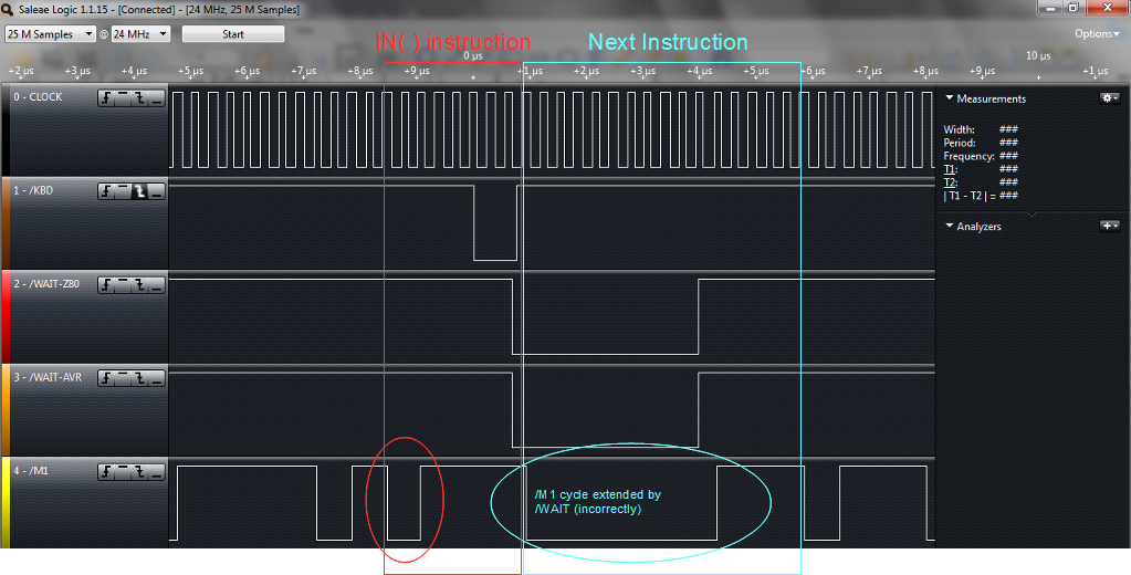
According to the Z80 manual during an I/O read cycle the time spent from the fall of /IORQ to the middle of T3 state (when the CPU effectively samples the signal) is a bit less than 2.5 CPU cycles or something close to 680ns (for 3.579MHz clock) which is a challenge for the AVR to respond.

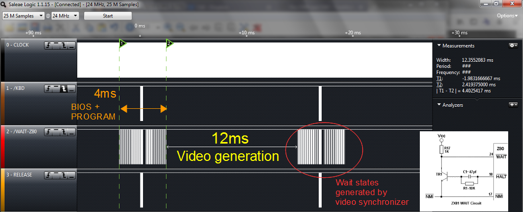
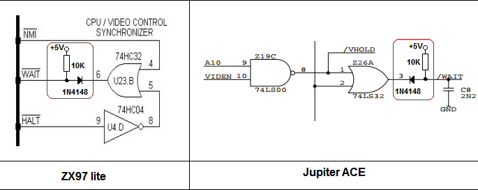
At the time the Z80 was created the designers knew that peripherals might take too much time to respond and provided a signal to pause the CPU while waiting for the external peripheral to respond. Such signal, named WAIT (really?!) is sampled between an internal WAIT state generated by the CPU between cycles T2 and T3, which occurs at around 500ns after the /IORQ signal go down.

Well, 680ns might not be enough for an AVR to enter and IRQ, sample the Z80 and respond with data, but 500ns is more than adequate to activate the WAIT line and then do wherever necessary and then release the Z80 from its idleness.

  • 1 × Arduino nano V3.0 ATMega328p prototyping board, 16MHz
  • 1 × 1N4148 Discrete Semiconductors / Diodes and Rectifiers
  • 1 × 74HC32 Electronic Components / Misc. Electronic Components
  • 1 × 74HC74 Electronic Components / Misc. Electronic Components
  • 2 × 100nf capacitor

  • Beta release!

    danjovic10/12/2019 at 07:14 0 comments

    I have found a bug that happened when DEBUG directive was active.

    I forgot to save the _temp_register_ on the beginning of the ISR and it caused the AVR to crash and reset while printing debug data to serial console.

    ISR (INT0_vect, ISR_NAKED) {
    
      asm volatile (
        "push __tmp_reg__\n\t" // <- THAT WAS MISSING!
        "in __tmp_reg__,__SREG__ \n\t"   // Save Status register
    
        "push r17\n\t"                   // keep PINB state
        "push r18\n\t"                   // keep PIND state
        "push r19\n\t"                   // temp Data to write on Output
        "push r20\n\t"                   // register to read keymap
        "push r26\n\t"                   // Pointer to Keymap
        "push r27\n\t"                   //
    ...
    

    After that was fixed the project began to behave like expected, so I am releasing it as a beta.

    I Will change the structure of the ".h" files to make easier to define new keyboard matrices (ZX81,Speccy,Ace) as well as new keyboard layouts (pt_br, en, etc).

  • Added option to generate code for ZX81 or Speccy

    danjovic10/08/2019 at 02:09 0 comments

    Now it is possible to generate code for ZX 81 or ZX Spectrum by commenting/uncommenting a directive.

    #define ZXMODEL ZX81
    //#define ZXMODEL ZXSPECTRUM

    Other models can be implemented as long by creating a pair of files:

    • A map of keyboard matrix
      /* Mapa dos bits da matriz de teclado do ZX81
         bit  7   6   5   4   3   2   1   0
              SH  -   c2  c1  c0  l2  l1  l0  
         c0..c2:  column [0..4] 
         l0..l2:  line   [0..7] 
         SH:      flag for SHIFT in composed keys (directionals)
      */
      // Keyboard matrix map
      //       Key      column   line       
      #define _KEY_1	  (0<<3) + 0 
      #define _KEY_2	  (1<<3) + 0 
      #define _KEY_3	  (2<<3) + 0 
      #define _KEY_4	  (3<<3) + 0 
      #define _KEY_5	  (4<<3) + 0 
      #define _KEY_6	  (4<<3) + 3 
      #define _KEY_7	  (3<<3) + 3 
      #define _KEY_8	  (2<<3) + 3 
      #define _KEY_9	  (1<<3) + 3 
      #define _KEY_0	  (0<<3) + 3 
      ...
    • A table to associate a PS/2 scancode to a bit (or more) to be activated in the matrix
    const PROGMEM unsigned char PS2Keymap_KEY_ABNT[] = { 
    _KEY_NONE,         // 0x00   
    _SHIFT + _KEY_9,   // 0x01  F9   (GRAPHICS)
    _KEY_NONE,         // 0x02  
    _KEY_NONE,         // 0x03  F5
    _KEY_NONE,         // 0x04  F3
    _SHIFT + _KEY_1,   // 0x05  F1   (EDIT)
    _KEY_NONE,         // 0x06  F2
    _KEY_NONE,         // 0x07  F12           
    _KEY_NONE,         // 0x08                
    _KEY_NONE,         // 0x09  F10    
    ...
    ...    

  • Enabling/Disabling the interface

    danjovic10/02/2019 at 04:26 0 comments

    It was noticed that during the boot of the AVR the Z80 was kept in wait state. Then an Enable signal was added simply by changing the Data input of the flip flop (pin 12) from fixed "1" to a pin coming from AVR. This pin shall be pulled down, so during AVR boot the Enable signal stays in "0" and no wait state will be generated.

    When the AVR is ready to work it can push a "1" on the Enable signal to enable the wait state generation.

  • How much the extra wait states cost to the performance?

    danjovic09/28/2019 at 06:15 0 comments

    The keyboard is read 9 times at each video frame (60/50Hz). I did expected that would be only 8, but I think that the extra reading might be to check the 50/60 Hz selection bit at D6.

    The keyboard reading pulse takes about 4.42us with the extra wait states and 0.75us (750ns) without them. The difference is 3,67us, being the total difference of 9 times this value or 33.03us lost at each frame.


    Some measurements performed showed that the ZX81 running at 60Hz has only 4.4ms (from a frame of 16.67ms) for drawing and within such time the video synchronization circuit generates 62 wait states taking 6us each (by the video synchronization circuit) .


    Doing the math...

    • net CPU time to run programs: 4.4ms - (6us*62) = 4.028ms
    • added time due to Tek extra wait states: 33.03us

    Then the cost of adding Tek V2 in CPU available time is a mere 0.8% decrease.

  • Using a free flip-flop gate as an inverter

    danjovic09/28/2019 at 05:34 0 comments

    After struggle for some time with a resistor and a diode, trying to make the /WAIT signal work properly I have decided to go back and use the Flip Flop like in the original design.

    The first flip flop (A) acts like an inverter and it is necessary to turn the negative going /ULARD  (/KBD) signal into a positive going edge to trigger the second flip flop (B) and generate the /WAIT to hold the Z80.

    The first flip flop is said free because we only need one flip flop to latch the /WAIT signal and the 74xx74 has two gates.

    The /ULARD signal also triggers the interrupt on the AVR (also on the falling edge).

  • Timing measurements

    danjovic09/26/2019 at 03:24 0 comments

    I did some time measurements on the response time of the "naked" interrupt. The test bench is a TK85 (ZX81 clone) that have a signal named /KBD that goes low when it's time to read the keyboard

    The /KBD signal goes to pin D2 on arduino (INT0). The interrupt is "naked" meaning it does not have any overhead to save the context.

    //
    // Update the state of the outputs according to the state of the Keyboard Matrix
    //  
    ISR (INT0_vect, ISR_NAKED) {  
       
    asm volatile (   
       "cbi %2,5 \n\t"                  // drop !WAIT line
       "in __tmp_reg__,__SREG__ \n\t"   // Save status register  
    ...
    ...

    The average latency of the signal  varied from 667ns to 750ns.

    The Timings Tx are related to the Z80 I/O Read cycle

    When superimposed, the measuremens become more clear (really??)

    The measurements above lead to the conclusion is that even the AVR with a  "naked" interrupt could not provide a response that is fast enough to activate the  /Wait signal on the correct time.

    Than can be seen on the measurement below, where the next instruction have its first cycle incorrectly extended by the AVR output

    So far so bad, but I still have some cards to play....

  • /KBD and /WAIT generator

    danjovic08/17/2019 at 04:26 0 comments

    That's a possibility for a /KBD and /WAIT signal generator.

    Everytime  the Z80 perform a READ at IO address xxxxxxx0 and the pin /RELEASE coming from AVR is at HIGH state, the output Y6 Will go LOW and will generate the /KBD signal to interrupt the AVR and also will signal Z80 to WAIT and the AVR will have more time to attend the external interrupt.

    Afther the correct data have been put on KB0-KB4 lines the AVR can drop the /RELEASE line for a period of time equivalent to the end of "IN (C),A" iinstruction (1us will do the job) and then return the /RELEASE line back to high level.

    I hope this mechanism can work without a companion flip flop, like in the external version.


  • Oooops!

    danjovic08/11/2019 at 04:00 0 comments

    I have completely missed that the ZX81 ULA does not provide an external signal for reading the keyboard. Same for TS1500.

    It is a pity but a a decoder required for these micros... a simple 74HC32 should do the job.

  • Issues with WAIT line on clones

    danjovic08/09/2019 at 23:12 0 comments

    On the ZX80/81 the /WAIT line is used to synchronize the Z80 with NMI timing twice during each video frame. The inverted /HALT line is ORed with /NMI using a transistor and some resistors.

    Some clone machines (even modern clones) have been designed using logic gates instead of a transistor.

    The problem with the latter designs is that a peripheral device (like my keyboard adapter) would fail to bring down the /WAIT line to hold the Z80, as the signal is generated by an ordinary TTL gate (instead of an Open Collector).

    It can be fixed though with one diode and one resistor.

  • Wish list...

    danjovic08/07/2019 at 23:37 0 comments

    Wish list

    • Selectable Keyboard Layout (US, ABNT, etc) 
    • Selectable target machine (ZX80/81, Speccy)
    • Get keystrokes from serial port  

View all 12 project logs

Enjoy this project?

Share

Discussions

Similar Projects

Does this project spark your interest?

Become a member to follow this project and never miss any updates