0%
0%
DIY EL Wire + 3D Printed "Neon" Sign!
I love the look of neon signs but they aren't particularly easy to DIY without glassblowing skills and equipment, so EL Wire to the rescue!
 sjm4306
Become a Hackaday.io member
Already have an account? Log in.
Just one more thing
To make the experience fit your profile, pick a username and tell us what interests you.
Pick an awesome username
hackaday.io/
Your profile's URL: hackaday.io/username. Max 25 alphanumeric characters.
Pick a few interests
Projects that share your interests
People that share your interests

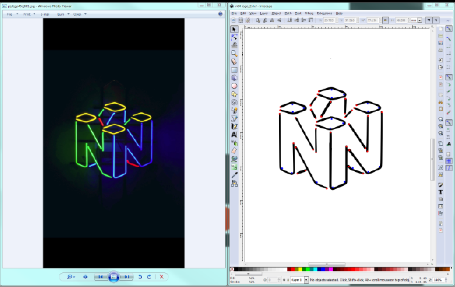 In inkscape I used the trace bitmap command under path to generate the light path using brightness to filter the image to that shown on the right above. Then I drew red dots for where holes would need to be on the frame for the EL wire to poke through and blue dots for support locations to bend the wire around. Finally I made sure the dimensions of the design were scaled to the desired final size I wanted the sign to be. With this done I saved the file as a dxf to allow it to be imported into solidworks.
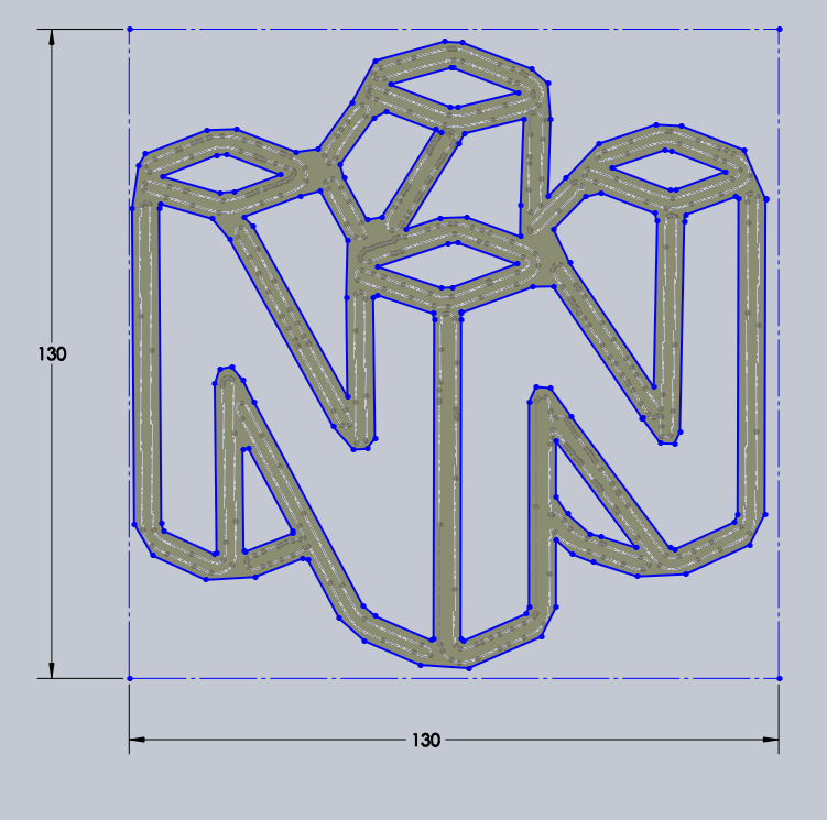
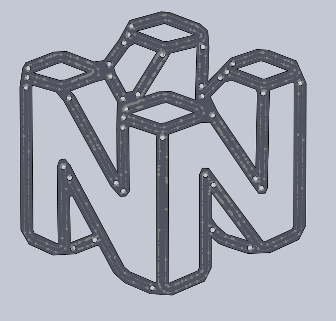 Next I had to make the protruding posts to wrap the EL wire around and give it shape. These were just circles that were extruded outwards and trimmed to match the edges of the frame.
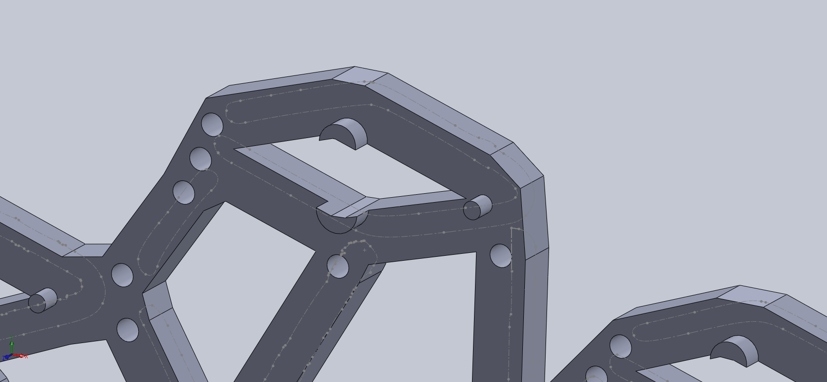 Finally I opted to fillet to round out the pointy edges of the frame (this isn't necessary, but will make it look a little nicer when printed out). The final step for solidworks is to save the design as an stl file so I can import it into cura, my slicer program.
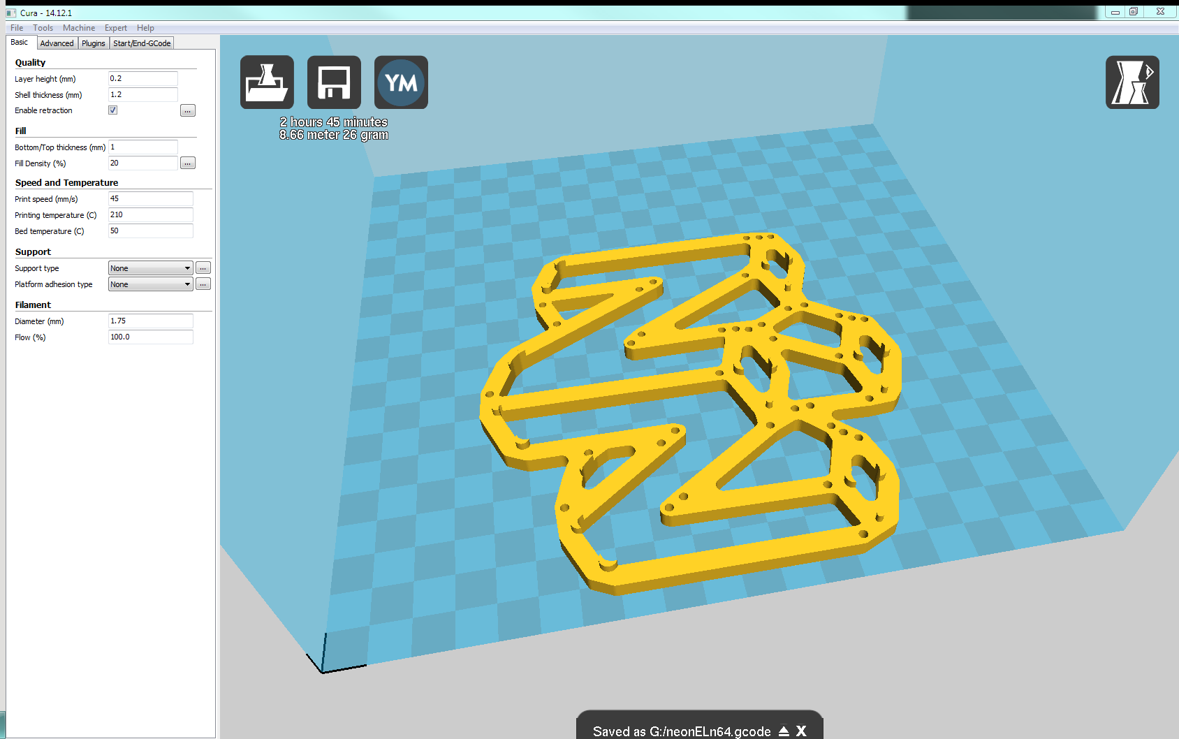 Once in cura (shown above) I can adjust the orientation and location of the print within my 3D printer's bed to ensure it fits as well as adjust parameters like print speed, infill and layer height. I print on a glass sheet from a picture frame I bought at a dollar store clipped to the bed with binder clips coated with a bit of hairspray and it comes out super smooth with great adhesion (but pops off with little effort once cool). The issue in my case is the glass is smaller than my bed area so I have to carefully place the print to ensure it is over the glass and make sure the bed height is correct each print. Other than that, roughly 3 hours later the print finished with no issues and I was ready to assemble. In the next project log we will see the assembly and wiring process to wrap up my first prototype.
 Russell Munro
 rohanoman
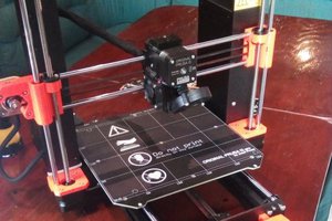
 Patrick