Close
0%
0%

Clap-Activated Applause Machine

Clap on a machine that claps for you! So efficient!

Similar projects worth following
1.1k views
0 followers
This project is an entry in the MacroFab Design Contest: Useless Machine.

While brainstorming for this design contest with a group of friends, one idea kept coming up: The Clapper. In this age of voice assistants and smart plugs, The Clapper is barely necessary, but everything becomes funnier if you need to turn it on by clapping: your cell phone, your refrigerator, your car.. But the best thing that can turned on by a clap is a machine that continues to clap for you! I couldn't get over this idea, and when I described it to visiting family, they also brought up that a machine that turns on by clapping will also use its own clapping to turn itself off. At this point, I knew I had to make this machine. This project describes my journey.

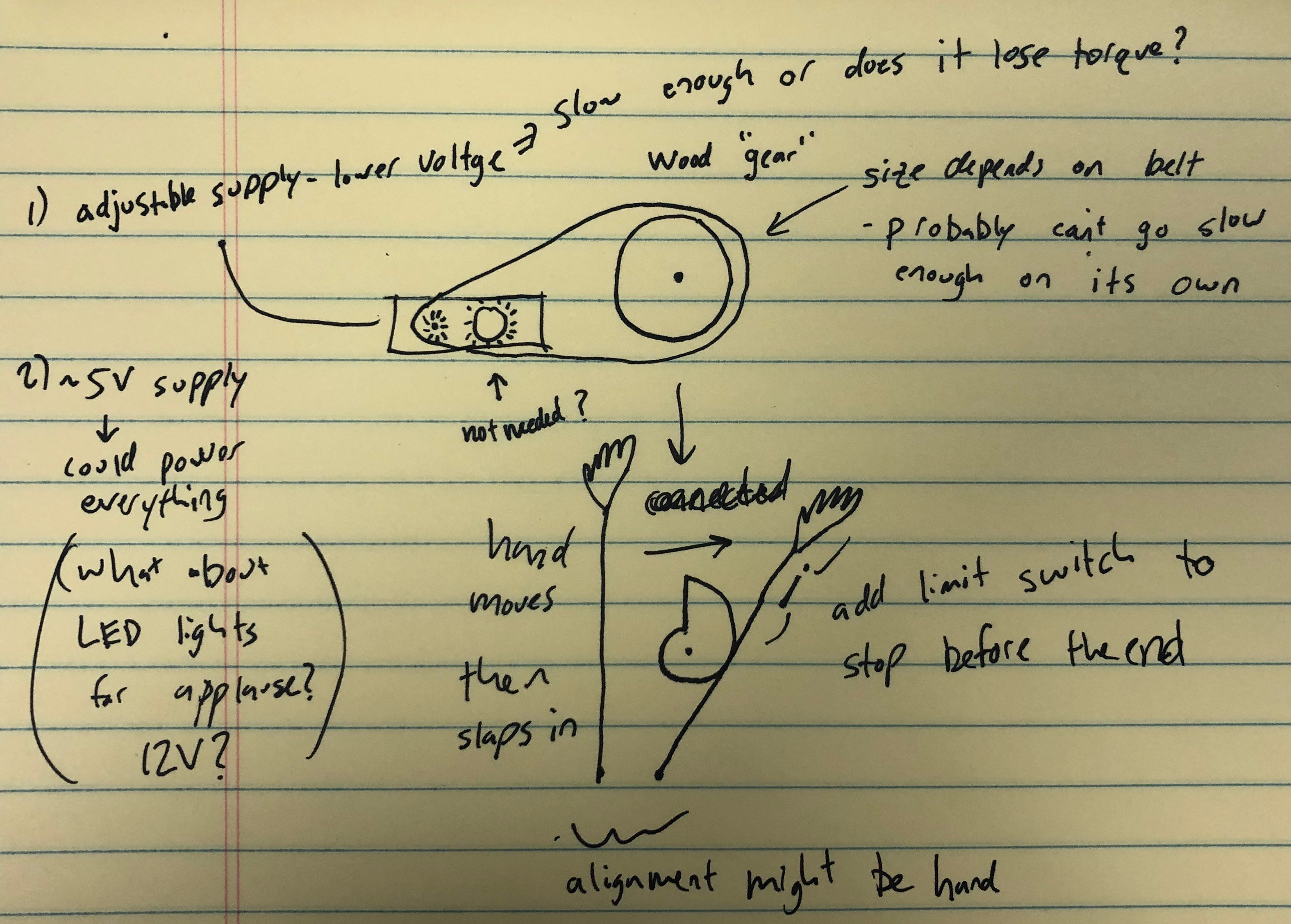
I went to school to become an electrical engineer and I'd also consider myself a maker, but the mechanical portions of this project really challenged me. This is the most complex mechanism I've ever made.

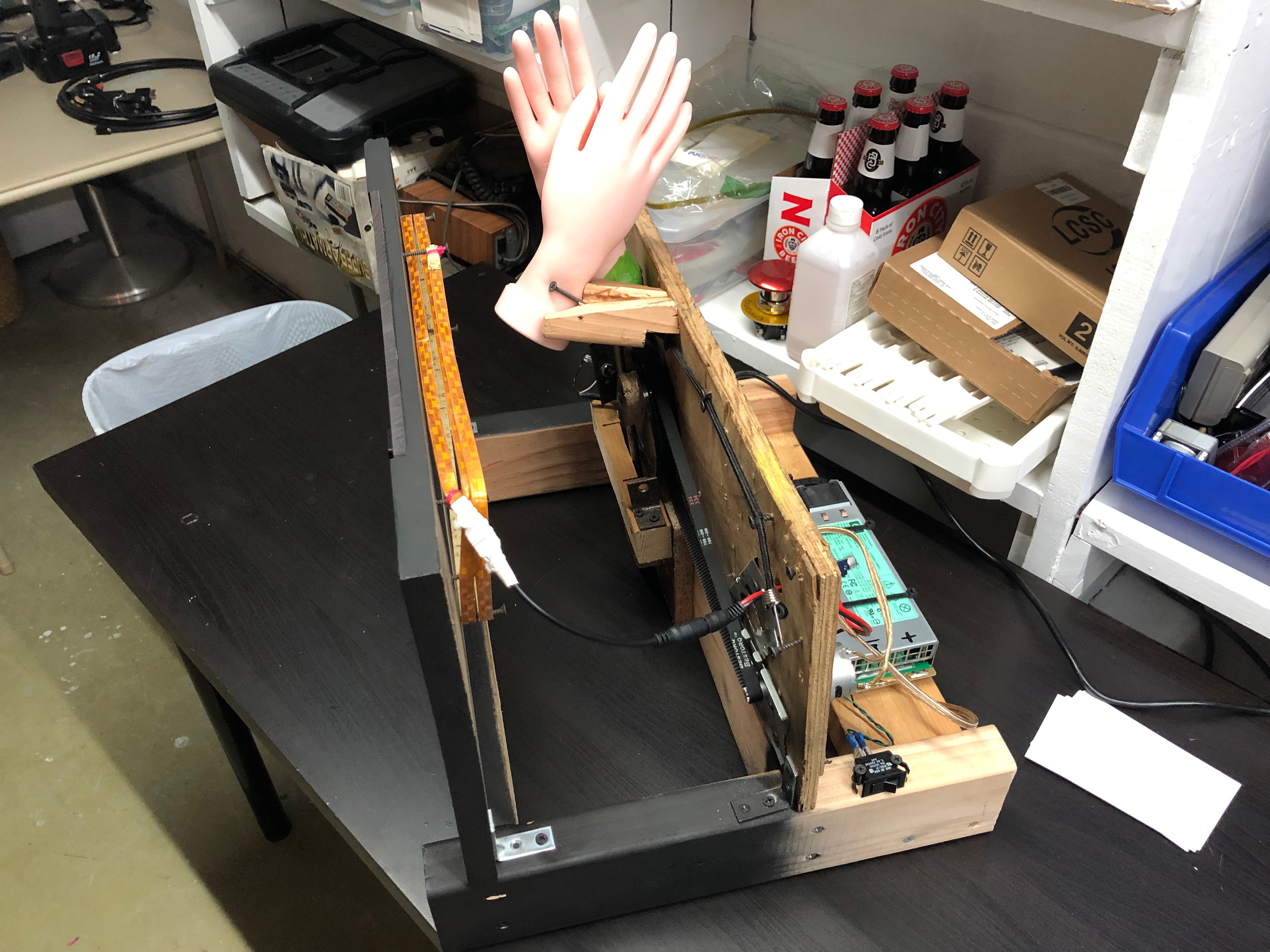
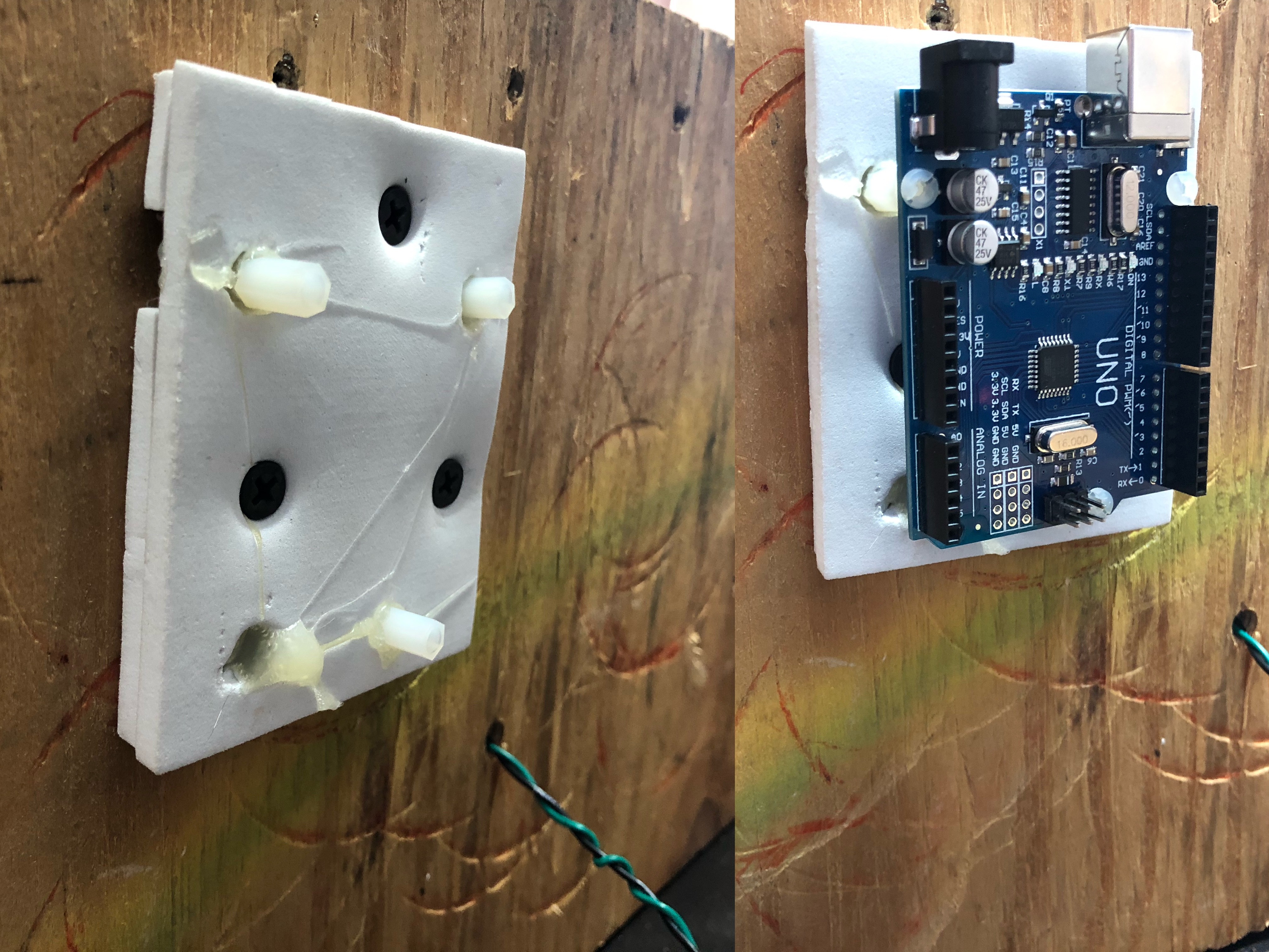
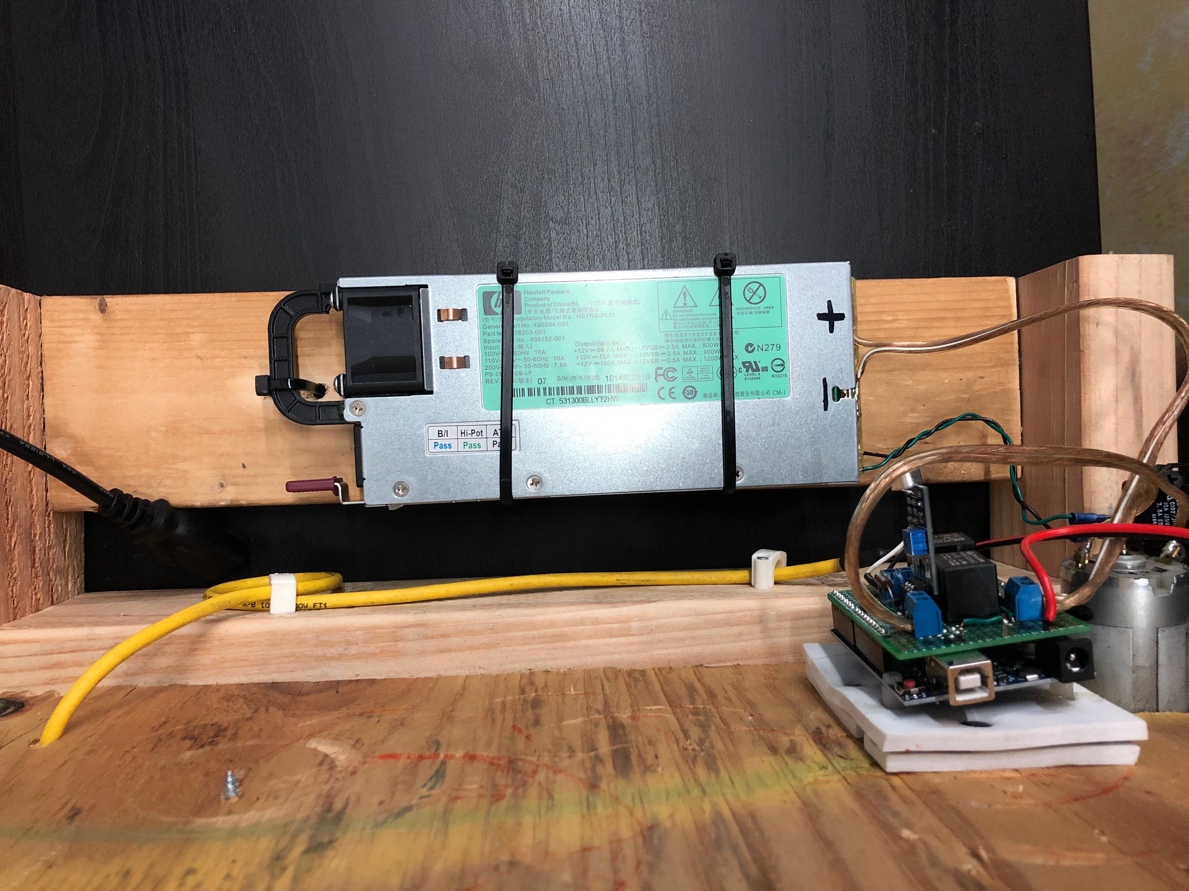
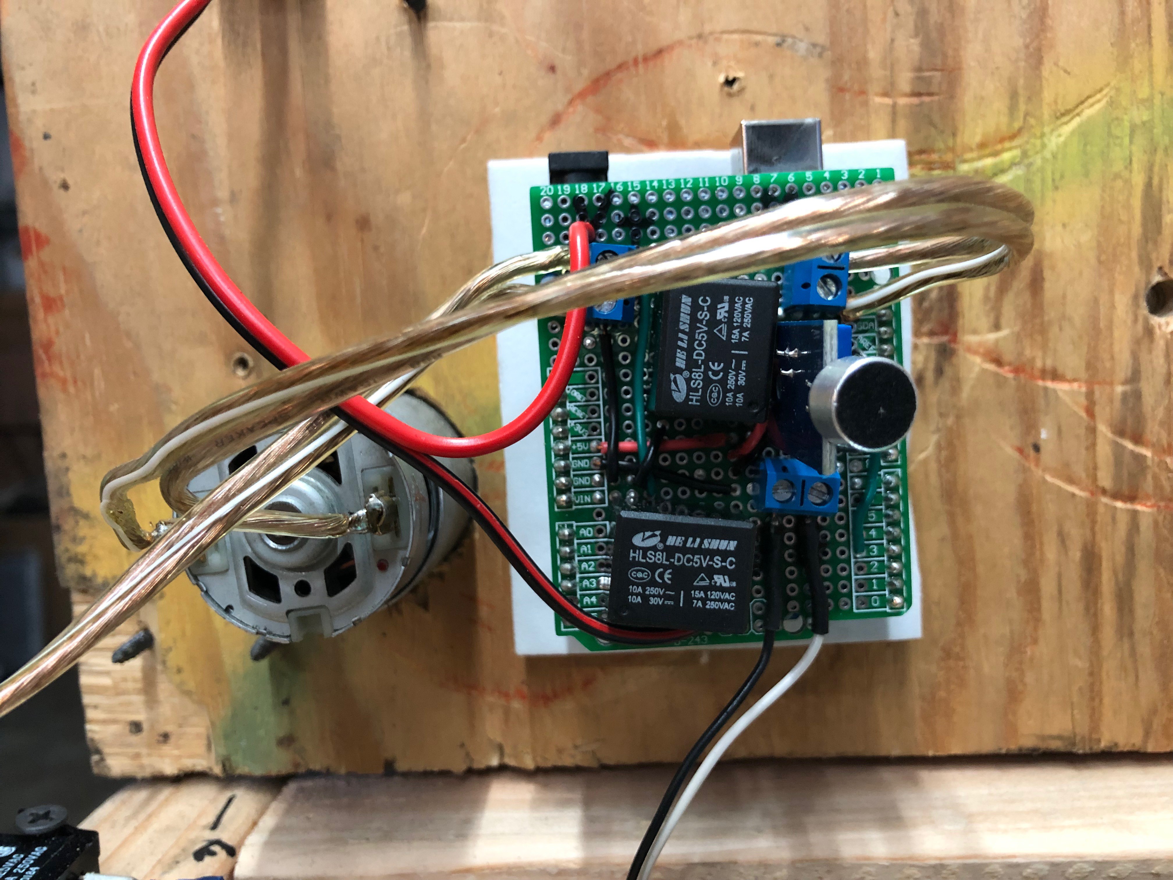
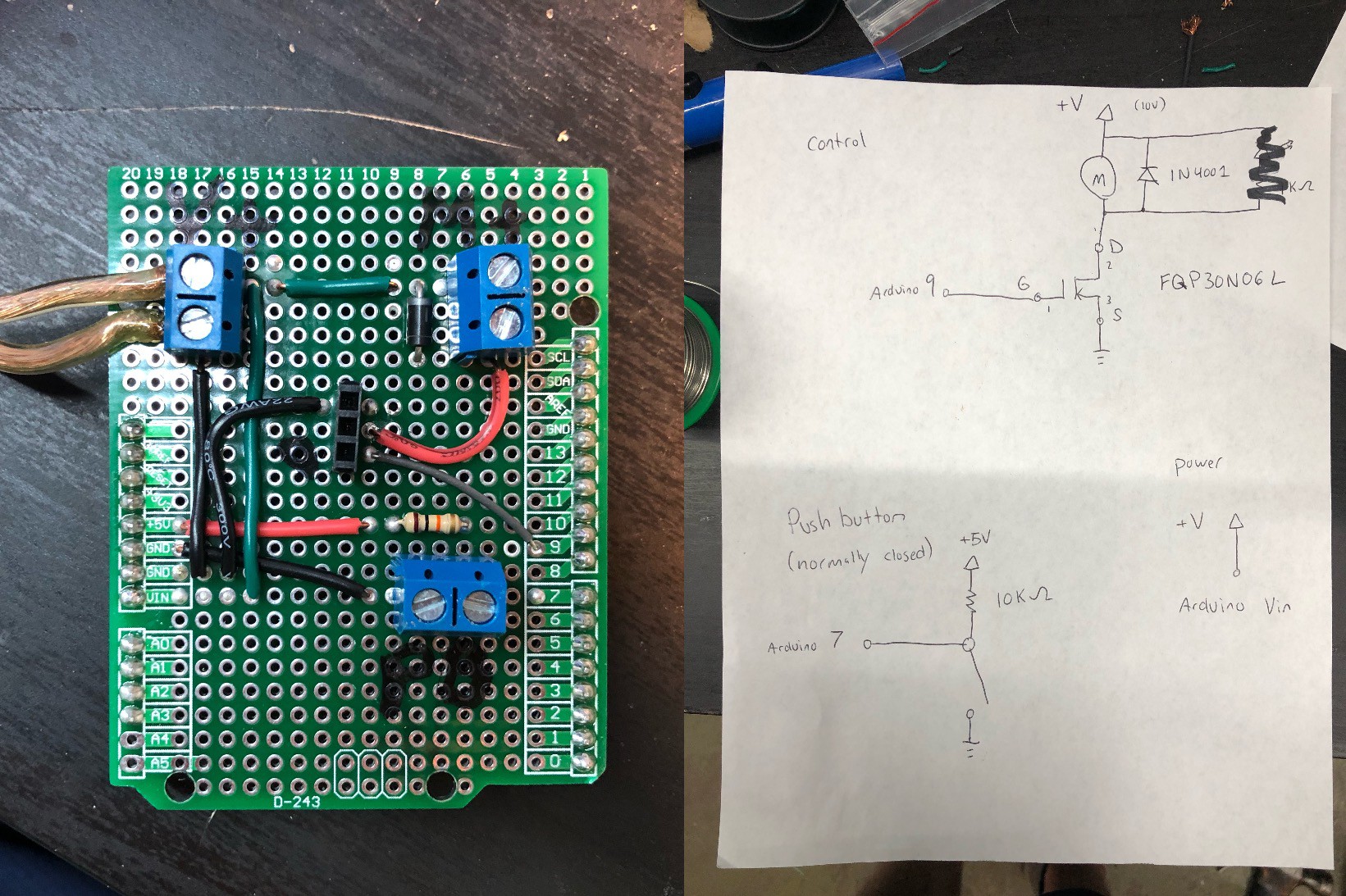
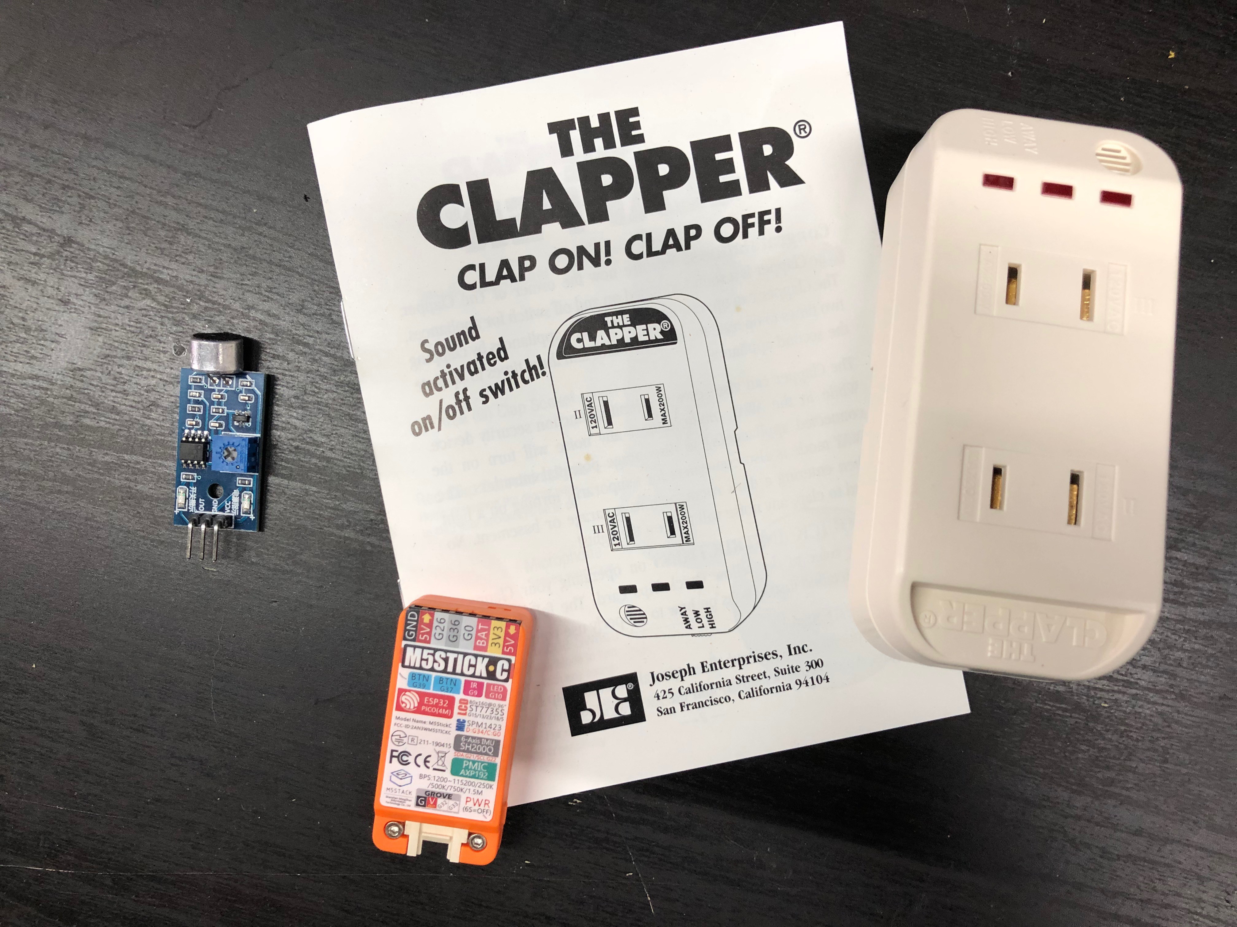
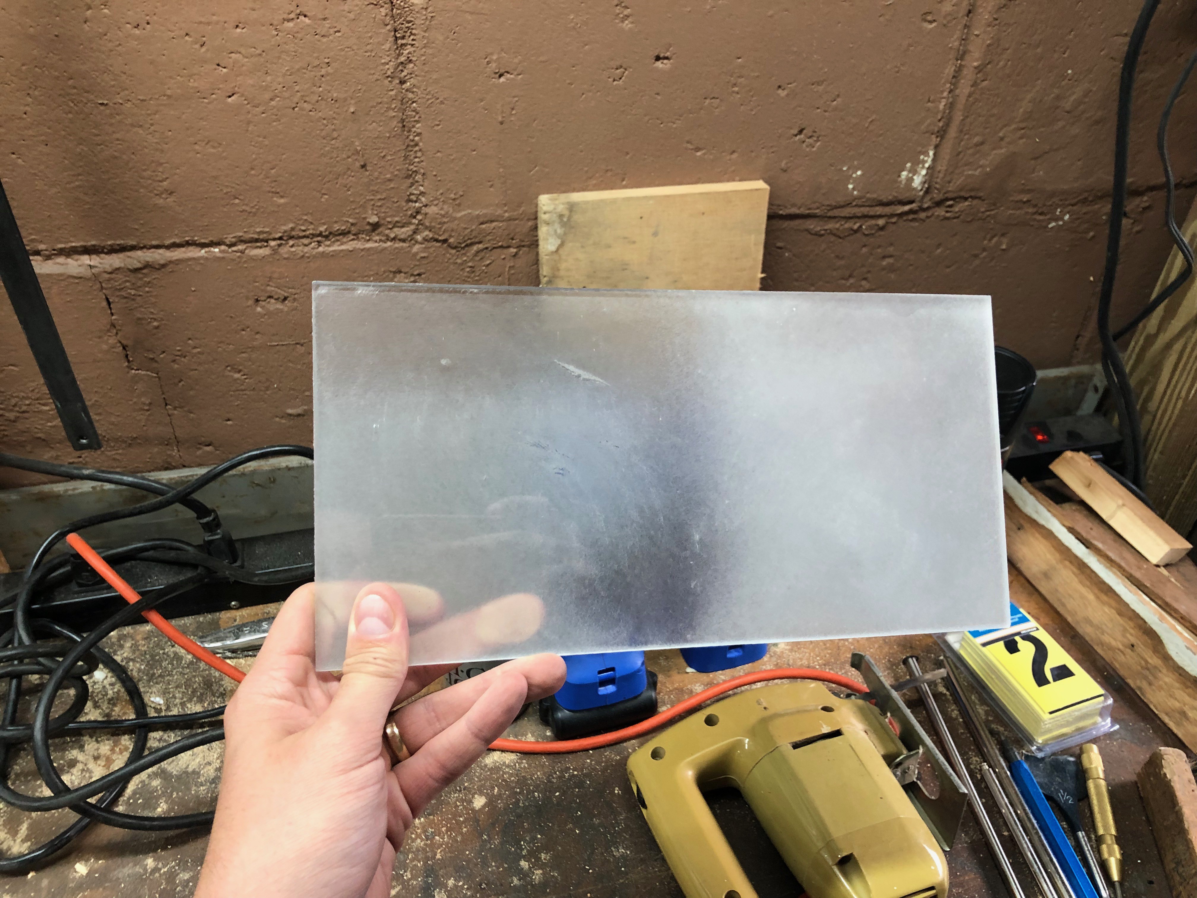
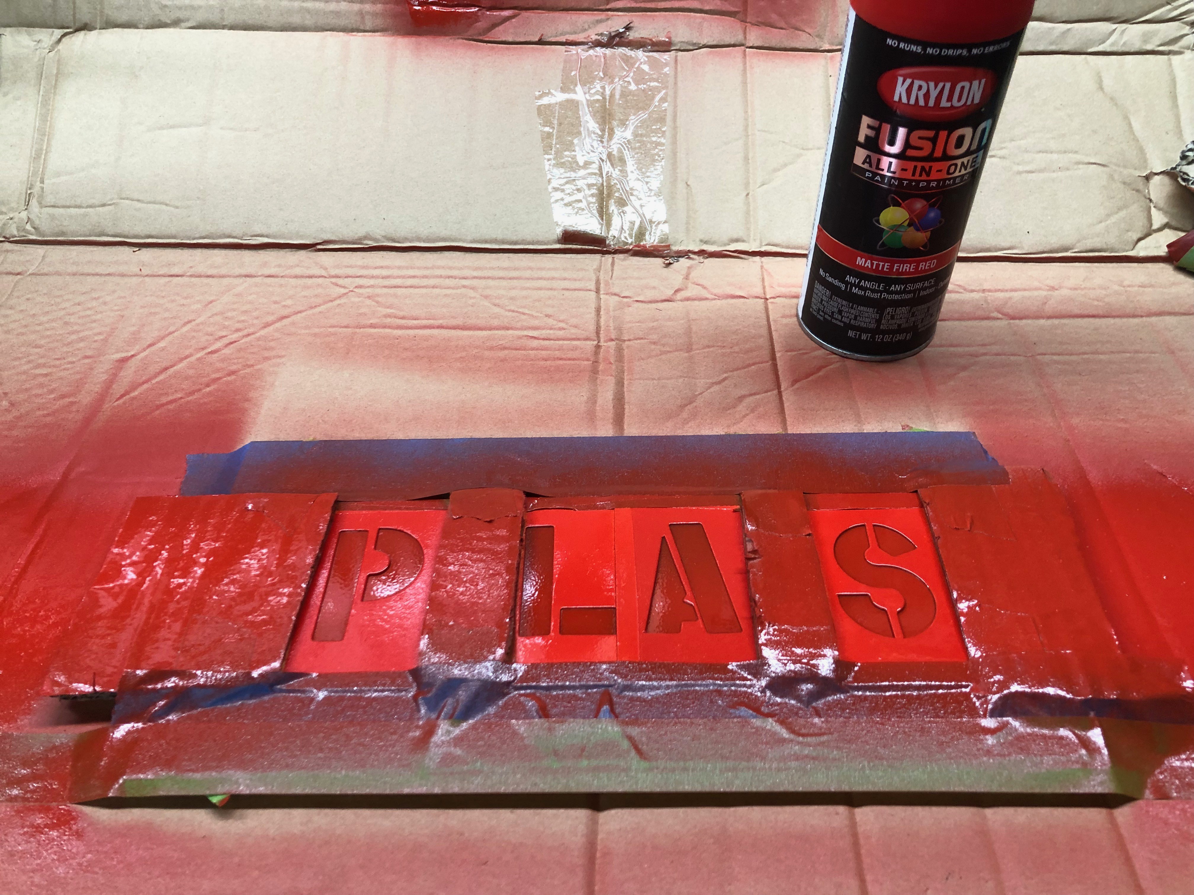
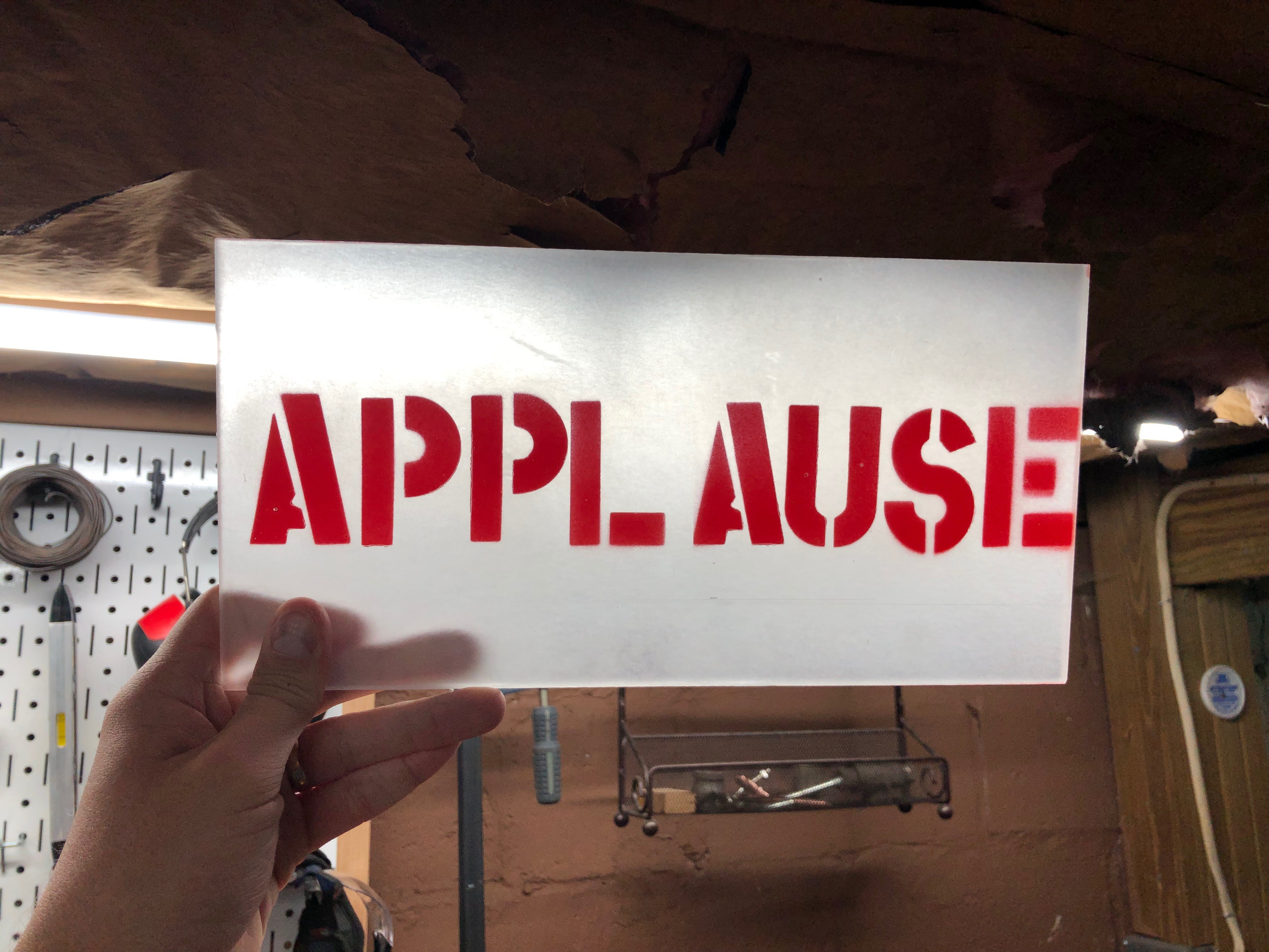
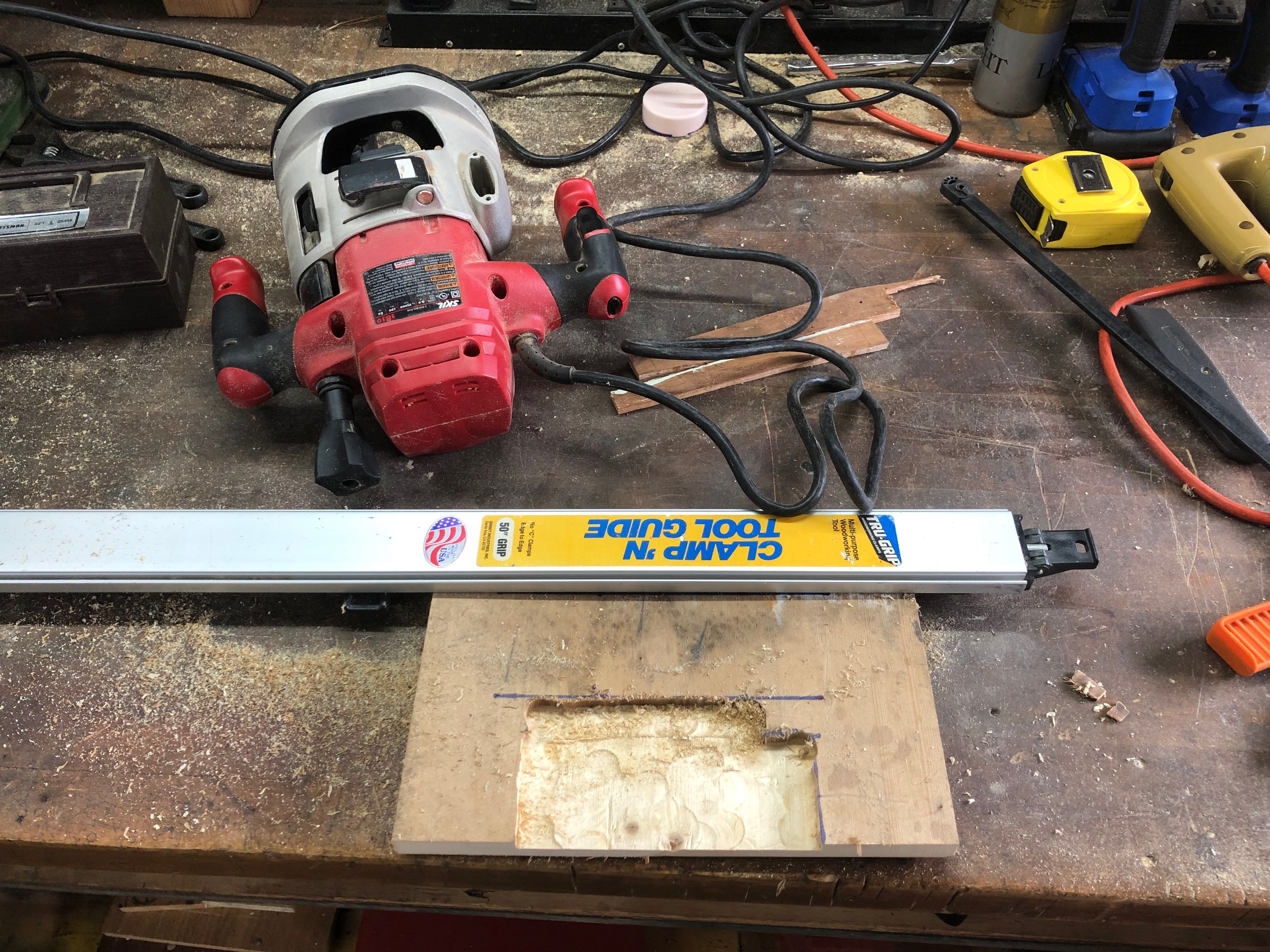
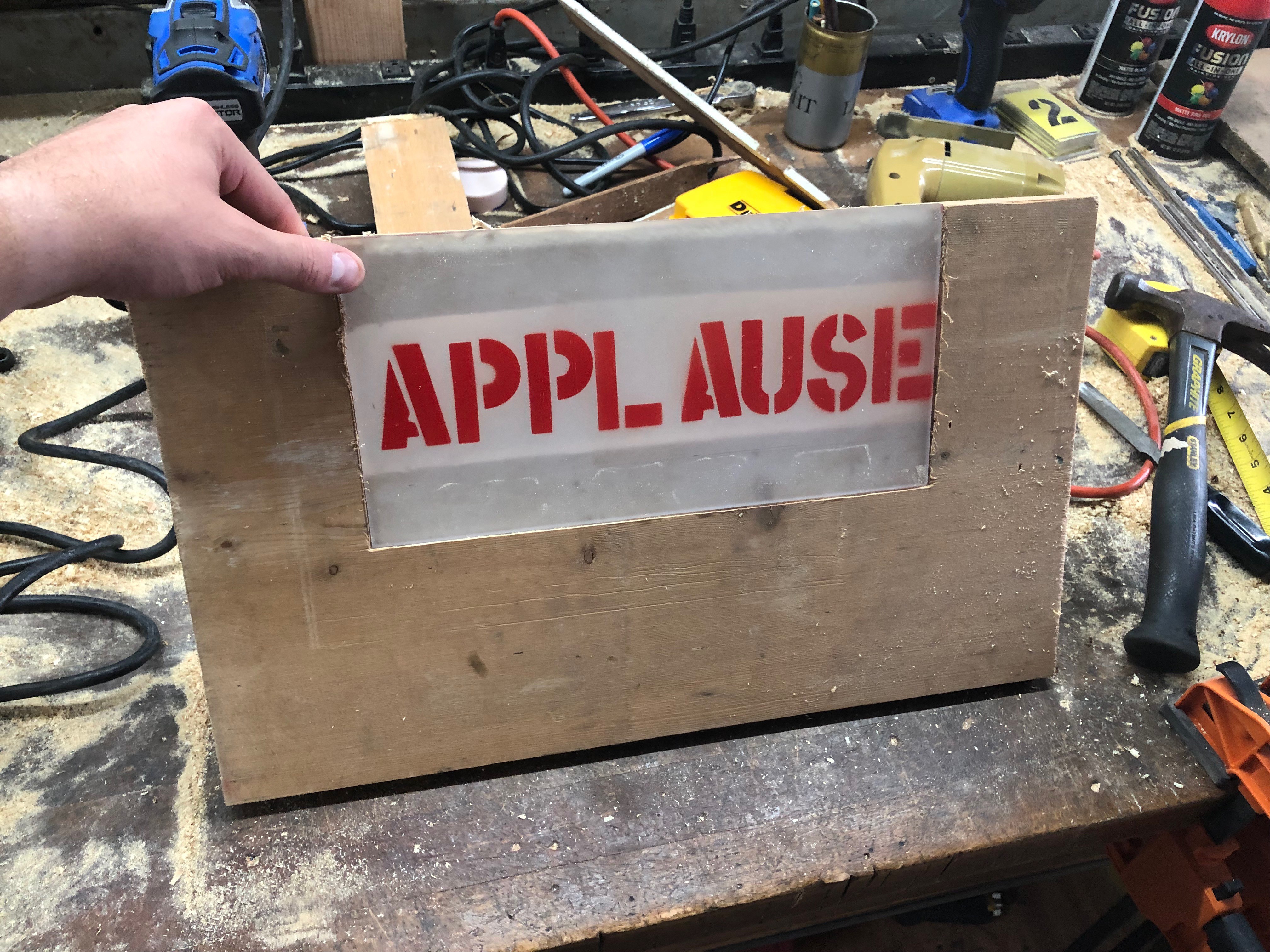
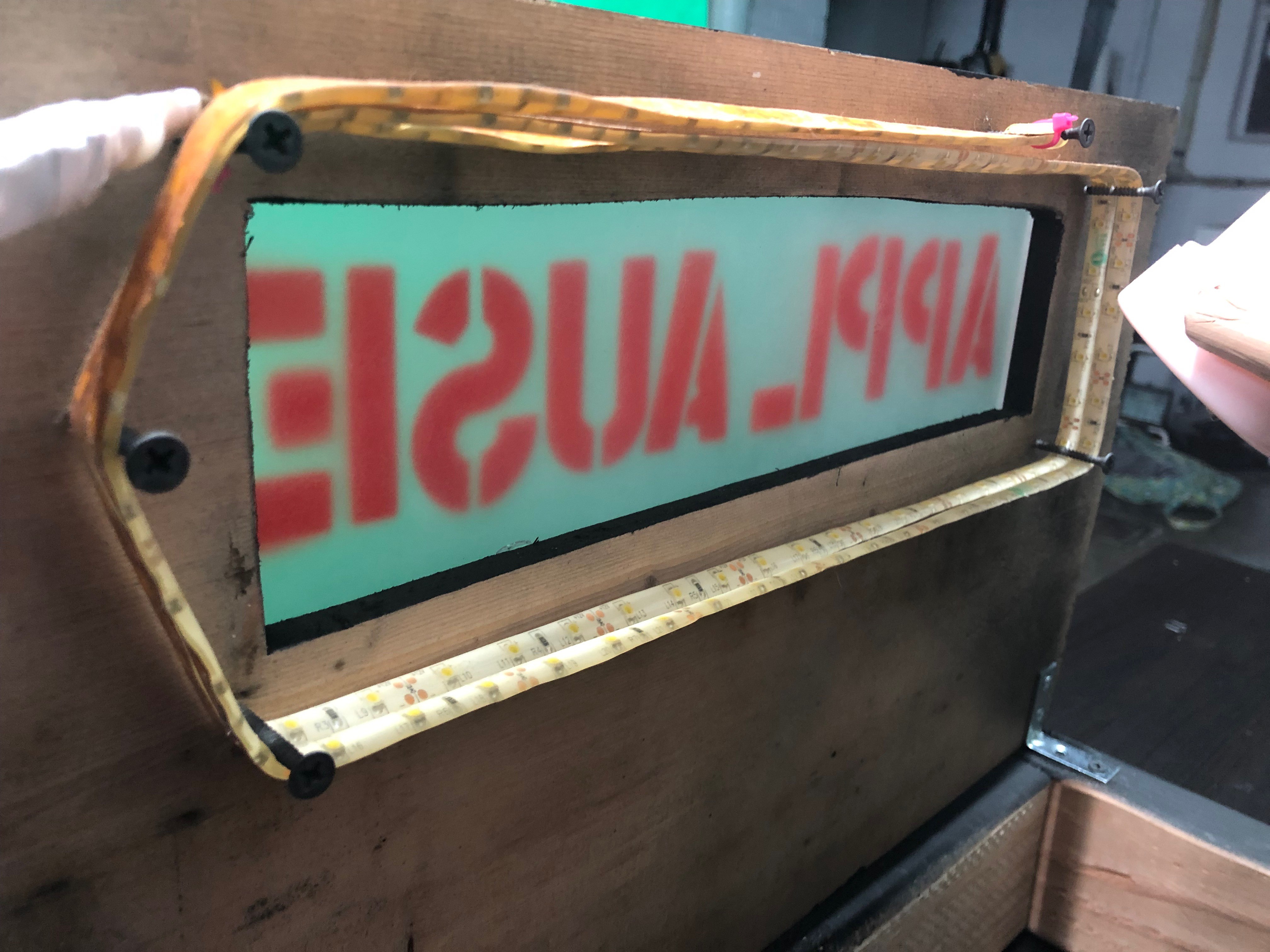
The electronics are mainly an Arduino with a homemade shield. The shield has a microphone to detect the claps to start, a relay to control power to the motor, a button to detect cam position, and another relay to control the Applause light which is an LED strip behind a spray-painted piece of plastic.

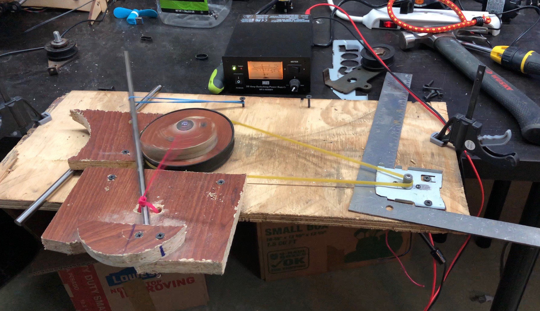
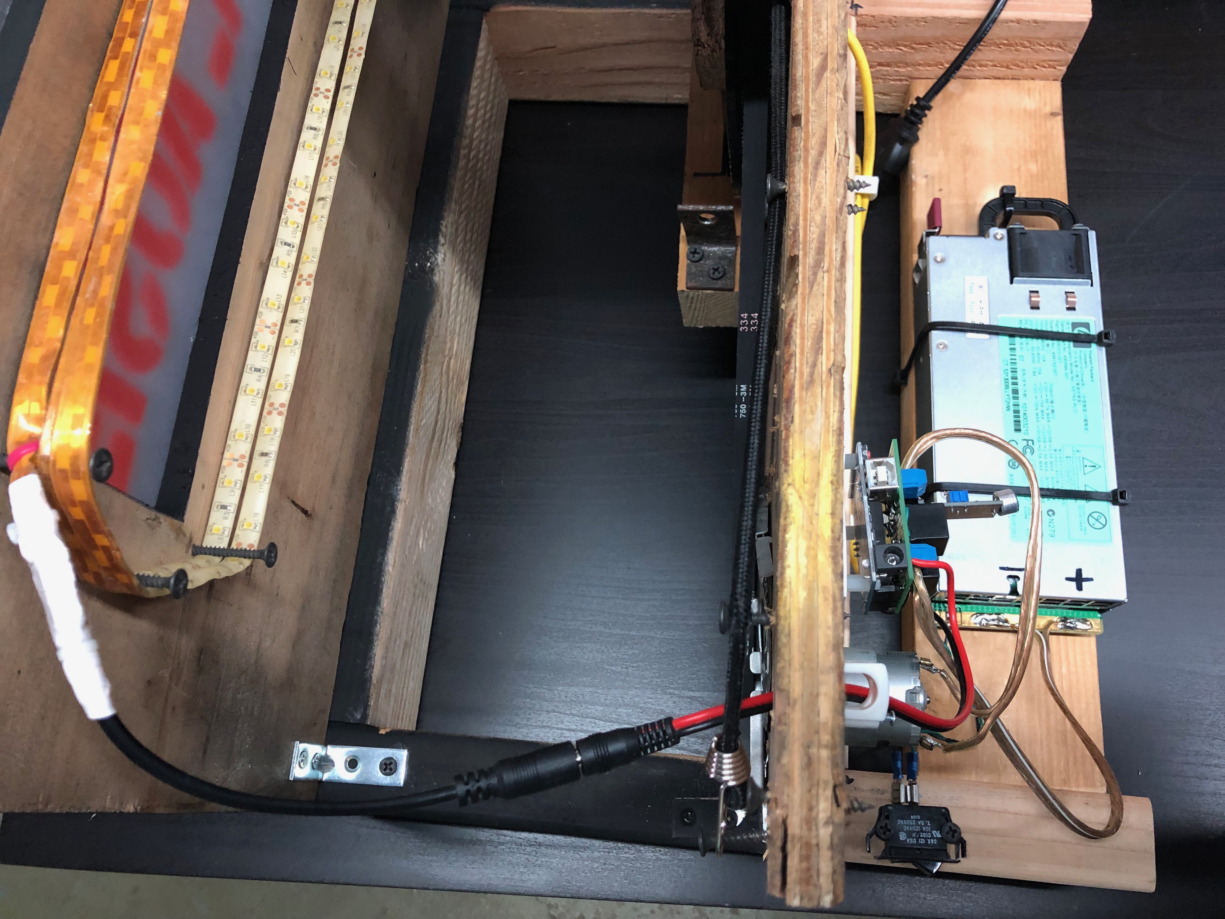
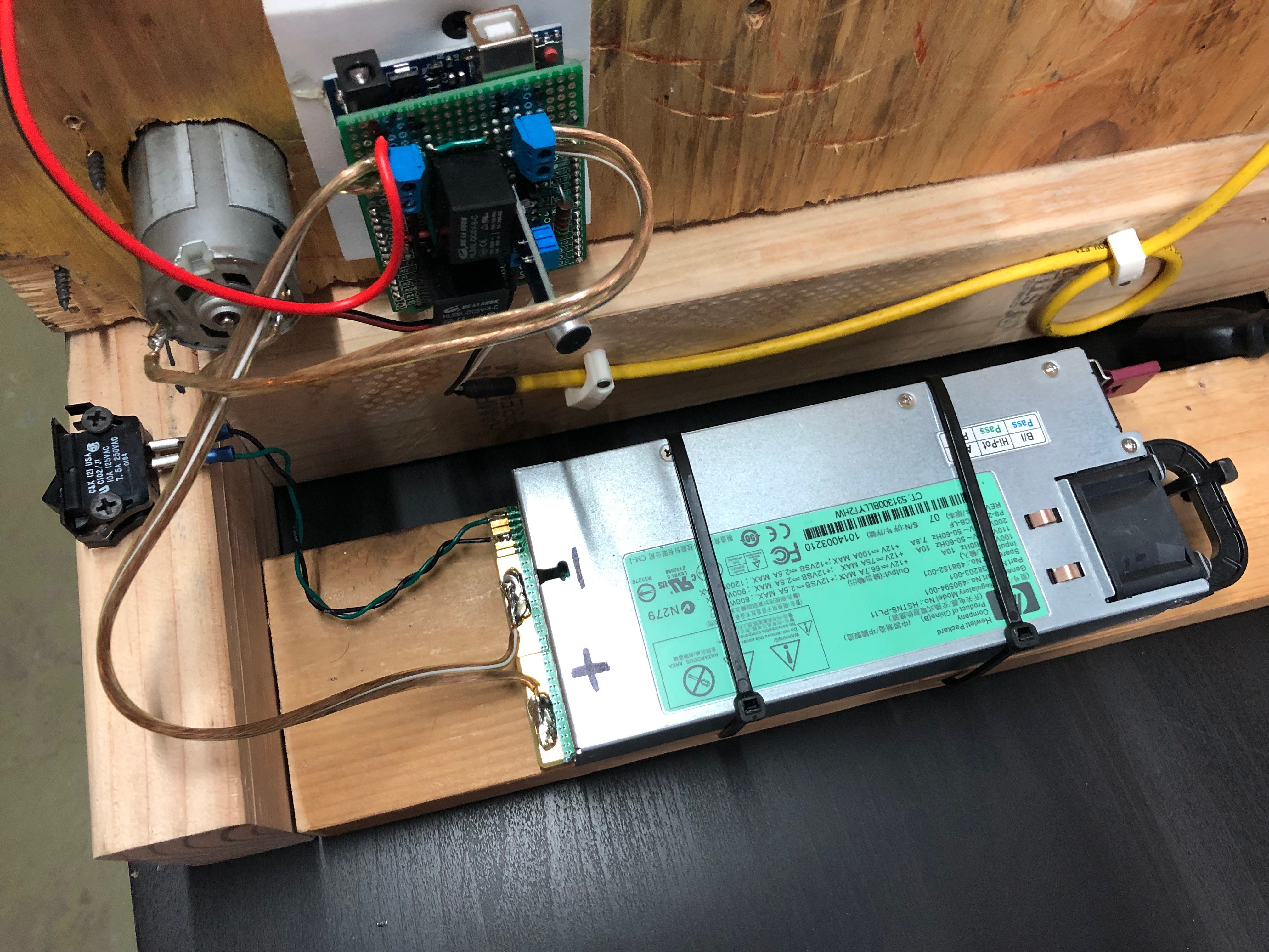
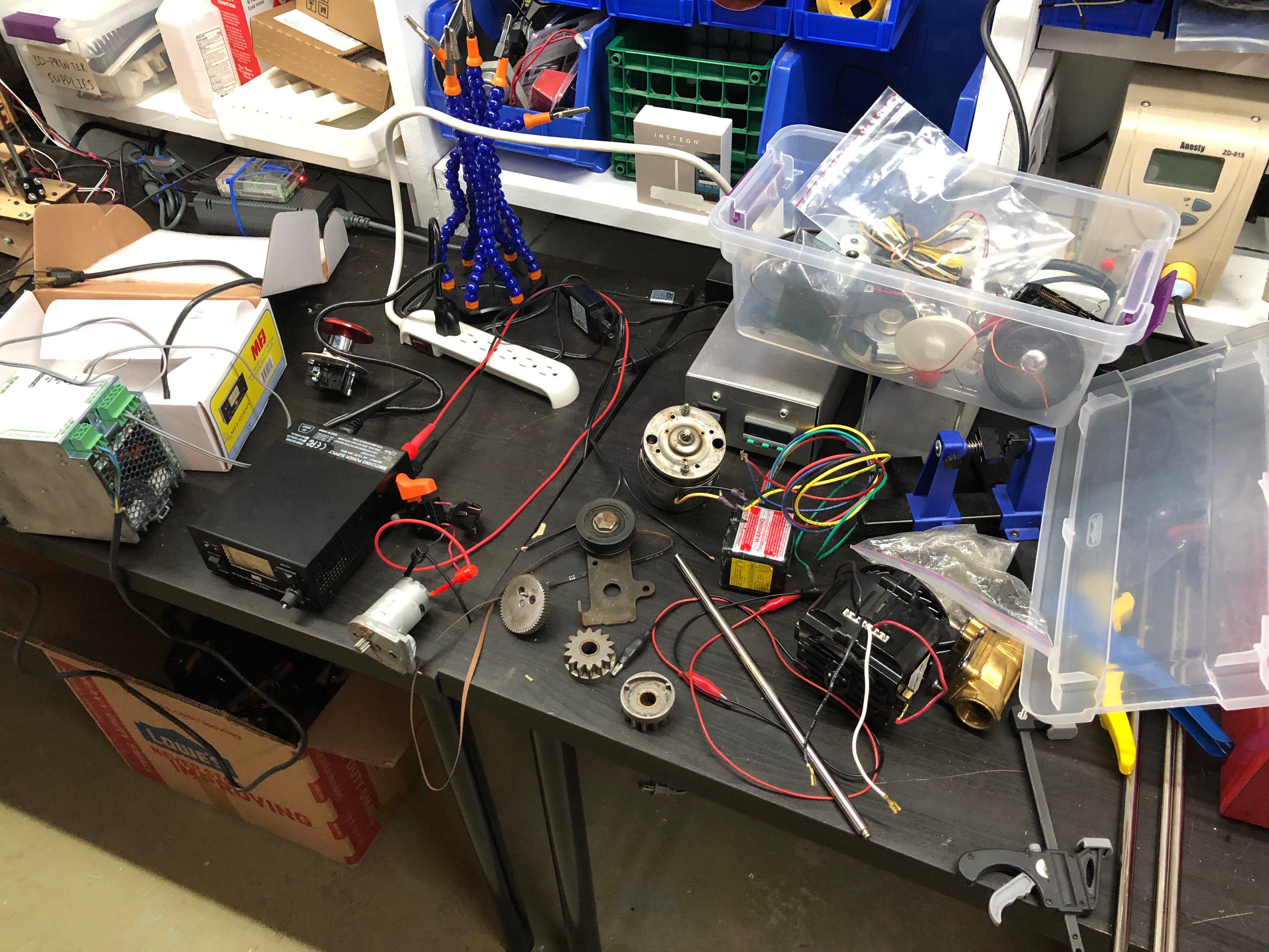
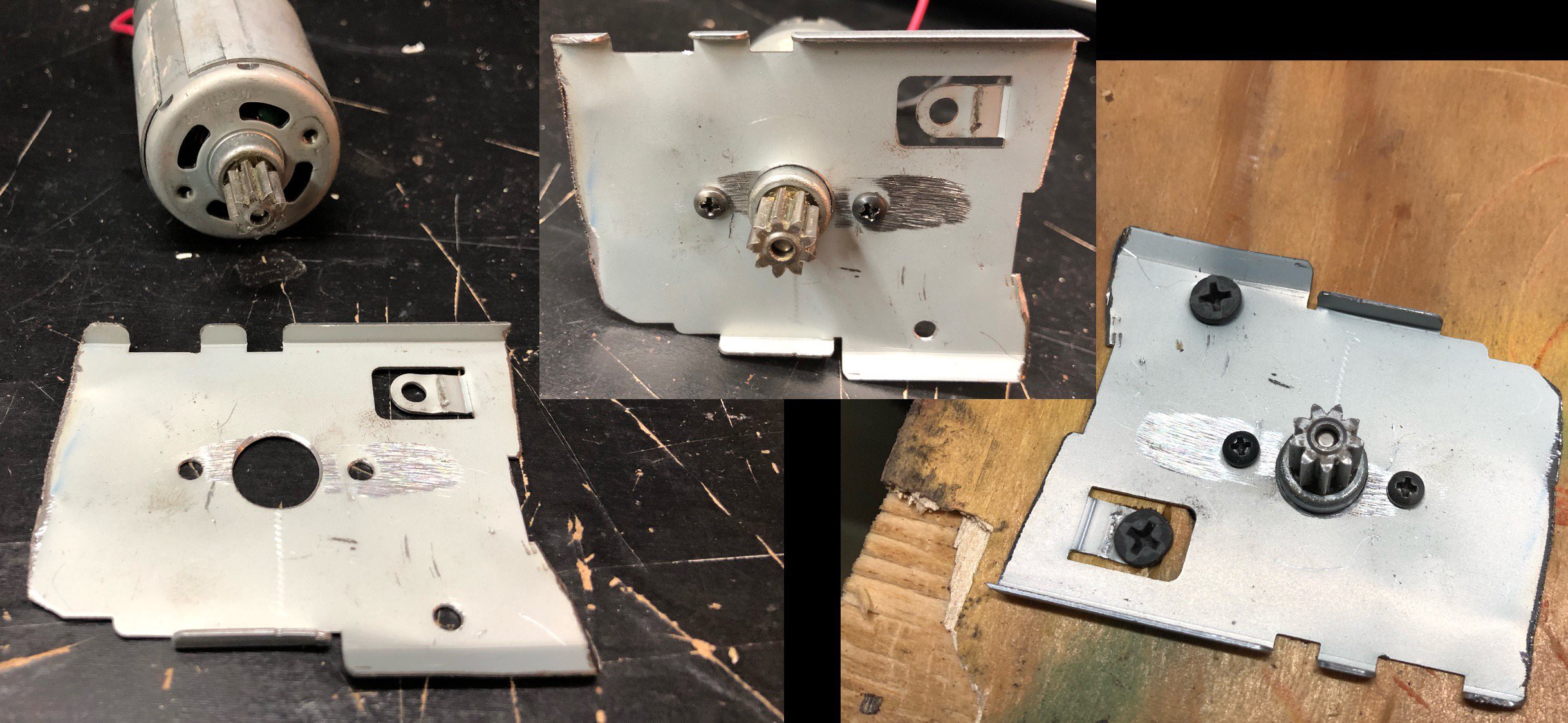
I think the motor came from a hedge trimmer and the power supply is from a server.

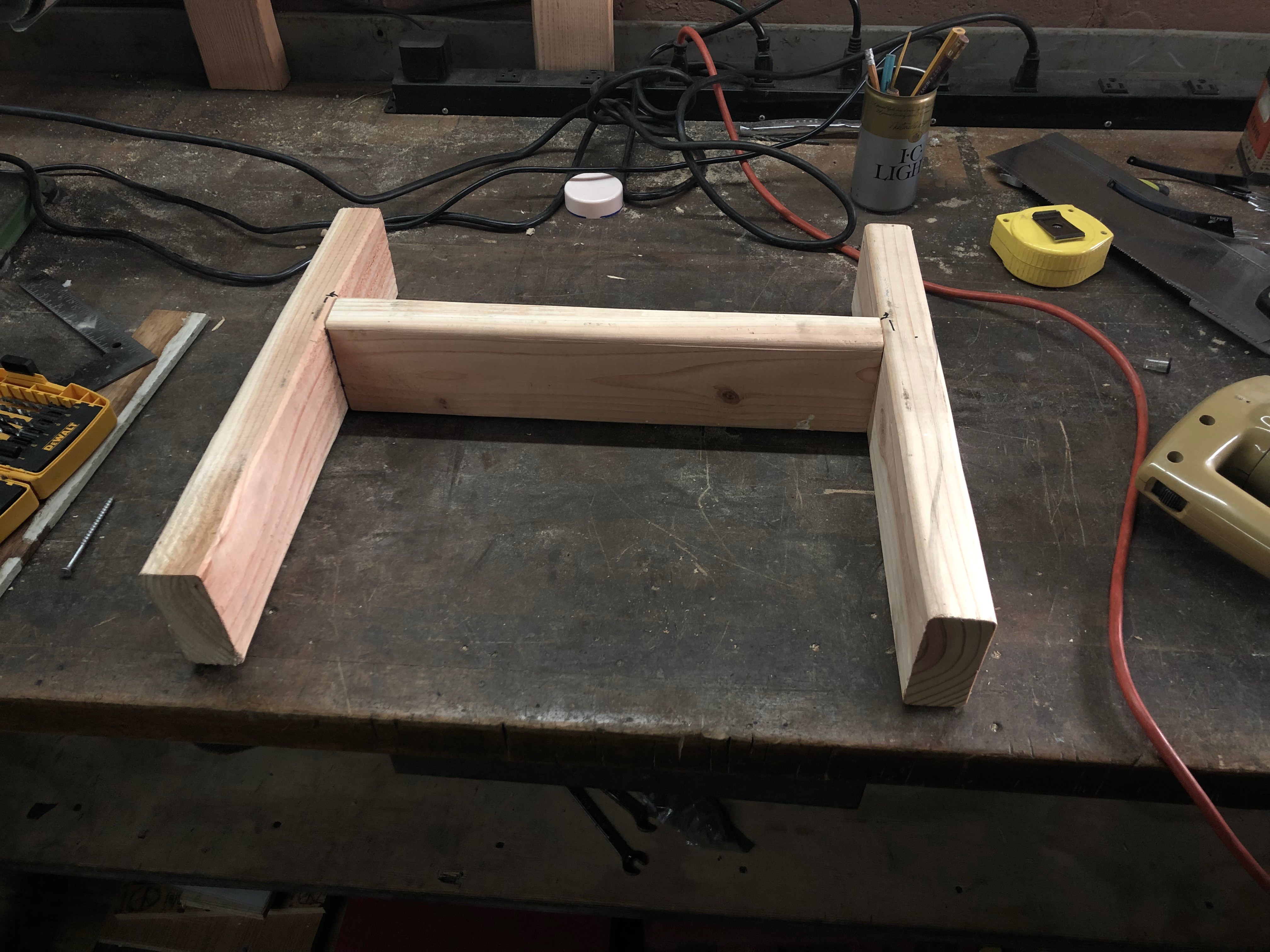
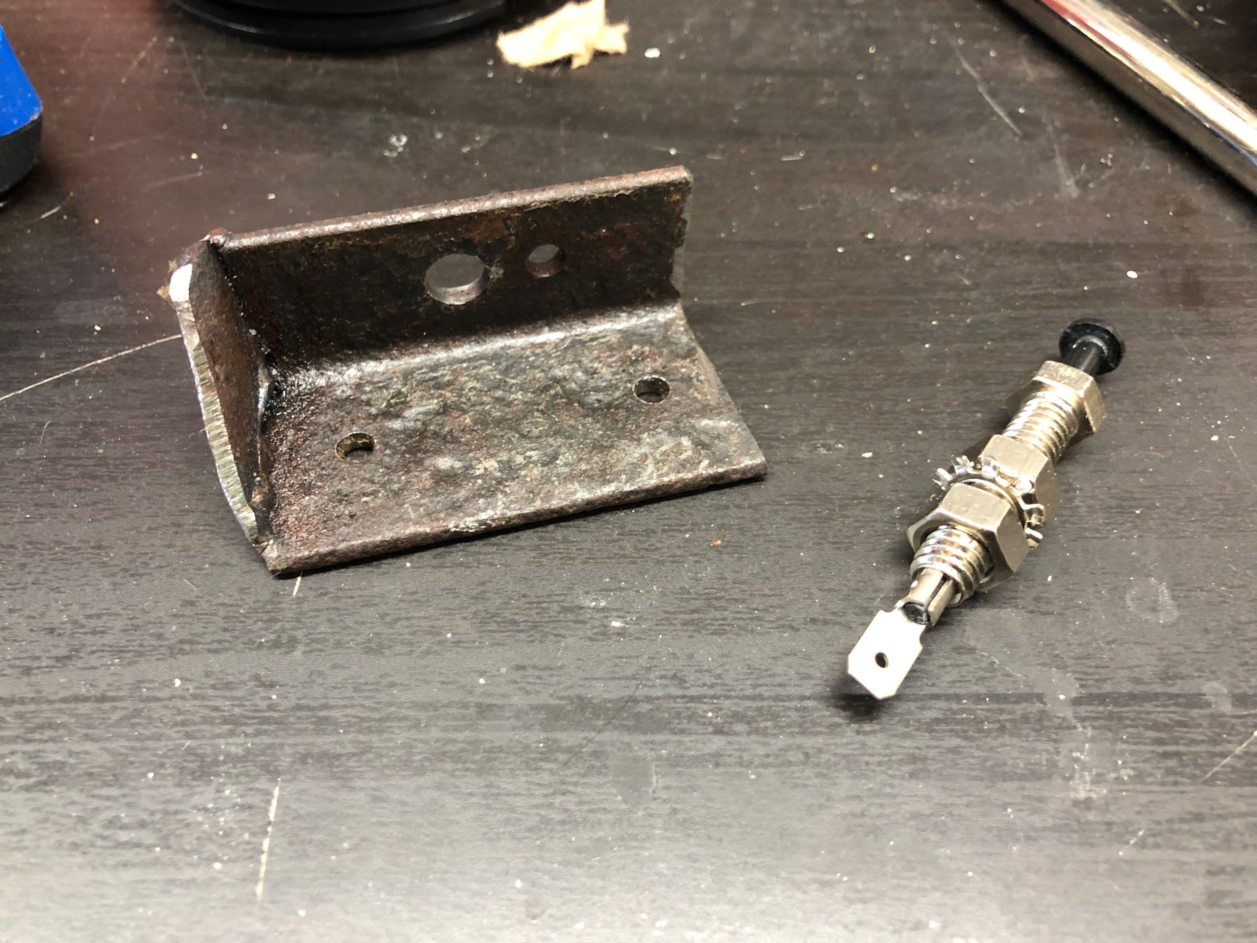
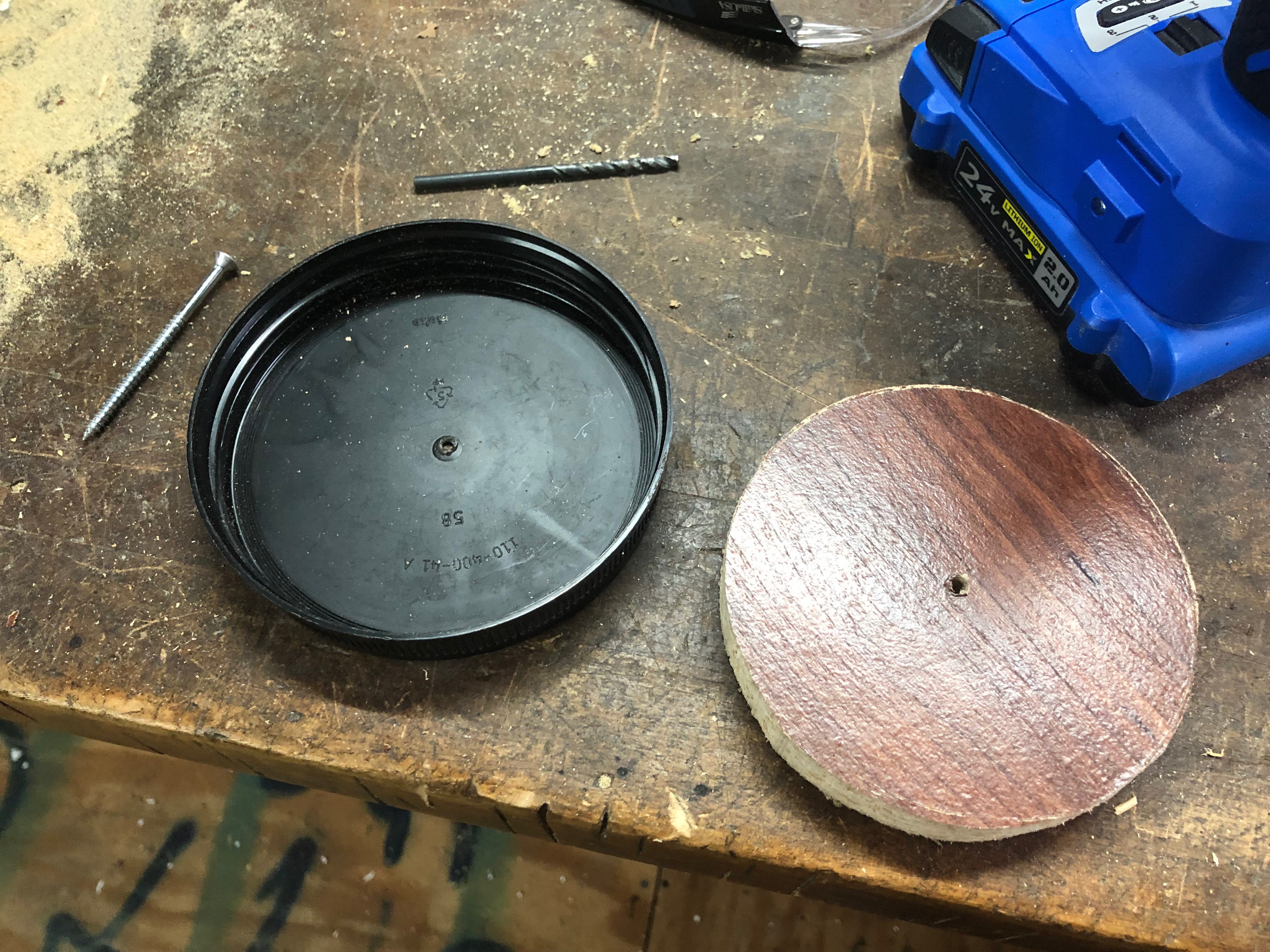
The remainder of the frame and mechanism comes from my junk pile: scrap wood and metal, a belt from a printer, a lid from a jar of nuts, a bungie cord, lots of screws.

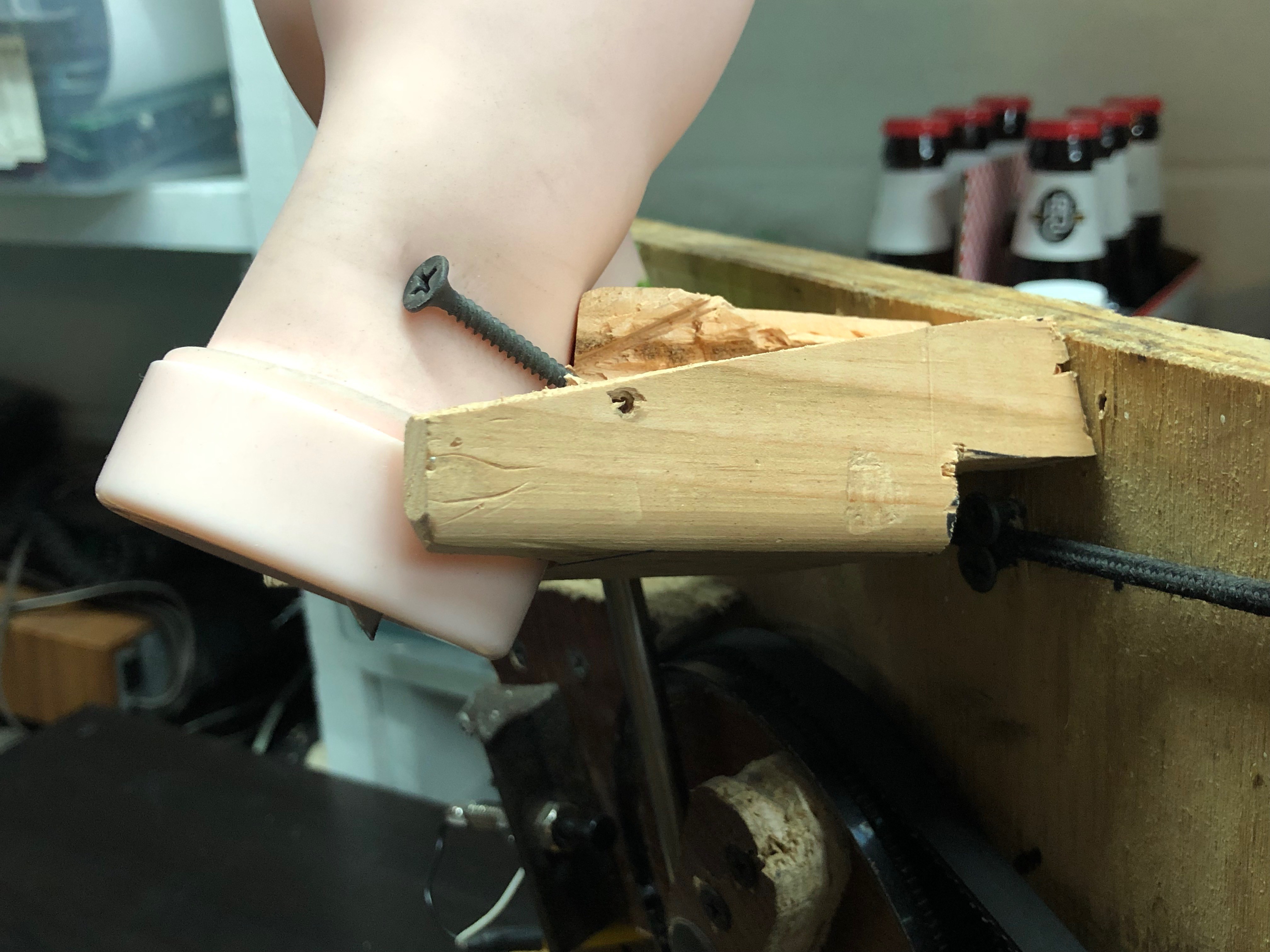
Oh, and the hands are meant for practicing nail art.

schematic.jpg

Hand drawn schematic for the custom Arduino shield

JPEG Image - 407.07 kB - 08/09/2019 at 15:43

Preview
Download

clapper.ino

Arduino code for this project

ino - 3.80 kB - 08/09/2019 at 15:42

Download

View all 9 components

  • The Frame

    Dillon Nichols08/07/2019 at 23:29 0 comments

    The last log on my machine is about the structure. I didn’t start with a final shape in mind -- I just built it one piece at a time and added on as I went. I started with a scrap piece of plywood and I never intended it to go into the final piece. I had my driver and a box of screws and just screwed things into place where they seemed right. This type of experimentation was refreshing compared to typical electronics work where it’s almost impossible to make a single change and not have it affect something else.

    I actually started with the wood flat on the table and when I eventually lifted it up to become more of a display piece, then the mechanism failed to work. I thankfully only needed some adjustments due to the new forces of gravity.

    After I got it working while it was standing, I designed an H-shaped frame out of 2x4 to permanently hold it upright.

    I used a mount that I used for my Arduino in a closet lighting system in my old apartment. The shield mounted to that and I could easily wire into the motor, power supply, lights, and button.

    The button holder is a piece of scrap metal from a tool I made. I drilled some holes to mount the button and screw it down. The strength of this piece has been perfect.

    I described the wood for the Applause light portion earlier but I cut that so it was the same size as the rest of the machine so it could hide all of the ugly internals. I mounted it to the front of the machine with angle brackets. There’s another piece of 2x4 under that to make the structure more rigid.

    This machine is meant to be seen straight-on from the front so I only spray painted the Applause light and the frame below.

    I had fun hacking away at the piece of wood that holds the stationary hand in place. I started with a pretty polished piece but as I went along, I kept needing to move it closer to other objects so I'd saw off a small chunk. Right now there isn't much left to it but it does its job. The hand is screwed in place.

    The last modification I made was mounting another piece of 2x4 onto the back that holds the power supply in place. It amazes me that a 1200W power supply is almost the exact size of a piece of 2x4.

  • The Software

    Dillon Nichols08/07/2019 at 23:11 1 comment

    The code is available on Github as a gist:

    https://gist.github.com/dwaq/35bf46b9d76081fec116b856d3b7ecda

    It is licensed under a Creative Commons Attribution 3.0 Unported License.

    This code is simple enough (and there's a ton of comments), but I'll still provide a brief overview. As a reminder, this code is for the Arduino Uno.

    The setup() function is line 85. Here we set up all the pins and attach an interrupt to the microphone. There's also various Serial prints throughout the code that I commented out but can be enabled to get a better idea of what is going on.

    Line 118 is the loop() function. Because I do the majority of my code in functions or interrupts, I made the loop() function only run once a millisecond. This code just takes care of the time between detecting claps and runs the machine to clap.

    soundDetected() on line 54 is called when the microphone detects sound. It sets some flags that are used inside the loop(). It also contains a flag to do some debouncing of the microphone input. If you recall, it's very noisy, and I debounce it here instead of adding a capacitor across the pins on the board.

    The next function is my clapAlgorithim() on line 37. You'll have to read the code yourself to see what that does ;).

    Final code is the clapWithDelay() function on line 101 that spins the motor one rotation and makes the hands clap.

    I hope you found this description useful! I'd be happy to help with any questions related to the code.

  • The Electronics

    Dillon Nichols08/07/2019 at 22:16 0 comments

    As mentioned in the description, the electronics are mainly an Arduino Uno with a homemade shield. The end result is fairly simple but it took quite a bit of effort to get to that point.

    I began by controlling the motor with my 30A adjustable power supply. I found that about 10V provided some good torque but it still spun too fast. I found a small DC motor driver but it couldn’t handle the motor’s current. First the flyback diode exploded and I replaced it with something beefier. After that, It worked,but the whole PCB was smoking. I had to find a new idea.

    At this point, I decided that I needed to start and stop the motor to add a delay between claps so I knew I’d need a microcontroller. For rapid prototyping simple ideas like this, you can’t beat an Arduino, so I used a protoboard shield and built my circuit up. This first version had motor voltage in (10-12V) that also powered the Arduino via the Vin pin and a logic level MOSFET (FQP30N06L) and flyback diode to control the motor which is connected via another screw terminal. I also added another connector for a switch that can be used to detect the position of the cam and stop it after one revolution. 

    I had a lot of issues with this circuit, but I eventually gave in and replaced the MOSFET with a relay. I didn’t use a relay at first because I was worried that it would be too loud, but it is silent compared to the overall mechanism (Rue Mohr did provide a circuit on Twitter if you want a solid state alternative). I rebuilt the shield with the relay soldered in place and it works well now. I should mention that I had a lot of troubles with the relay “welding” itself on. This seems to be a problem when too much current goes through the relay and the arc welds it shut. I read that one way to fix it is to just let it happen over and over again until the pads are built up and it won't happen anymore. This either fixed it or the better power supply did.

    The next task was controlling the Applause light. This one uses another of the same type of relay that the motor uses. I turn the light on when the clapping is detected and turn it off after the whole process is complete.

    I actually bought an official Clapper to use for this project, but it doesn’t work with how much noise the machine makes. The Clapper has to have proper timing between claps with silence and a period of silence afterwards that my machine can’t make. I knew I needed to make my own clap detection circuit so I searched for a few different options. The first one I tried is a M5StickC with a built-in MEMS microphone. I chose this because it was battery powered and I thought I could just turn on the power supply when it detects a clap and it would automatically run. Unfortunately, the microphone’s communication seemed too slow to detect the sharp sound pulse of a clap. There may be a method to make this work but I didn’t want to become an expert on the SPM1423HM4H-B microphone and I2S communication ust to detect a clap. The next option was a basic microphone breakout that took power in and gave a digital output when noise was detected. I set the threshold of the onboard potentiometer and originally put a capacitor from the output pin to smooth out some noise and it worked perfectly as a trigger. I removed the capacitor when I changed the pin to an interrupt because I only cared about the first pulse. The rest could be done in code.

    Now that the system was working as a whole, I noticed that my 30A bench power supply couldn’t keep up to the motor’s current draw. It would brown out when the motor turned on which was obvious looking at the applause light, but would also sometimes even get low enough to reset the Arduino and then the clapping would never stop. I went searching on Mouser for another power supply but 12V supplies with >30A current are super expensive. The cheapest option I found was about $50. My next step was to turn to eBay, where I found this project’s saving grace…...

    Read more »

  • The Applause Light

    Dillon Nichols08/06/2019 at 02:02 1 comment

    I’ve never been to a taping of a TV show, but apparently there are illuminated “Applause” signs to tell the audience when it is appropriate to clap. I used this idea to clean up the looks of this machine and hide the messy mechanism.

    I made an art project in school with where a light is diffused behind a piece of plastic. I recreated that effect in this project. I had a piece of plastic that I sanded with a random orbital sander with 120 grit sandpaper to create the diffused effect. In the above photo, you can see the difference between sanding just the front side (left) and both front and back sides (right).

    I bought some stencils and red spray paint and added the word “APPLAUSE” to the plastic. The stencils are overall wider than the plastic (and some letters are repeated) so I had to paint this in two steps to get the desired output.

    The next step was mounting this plastic to some wood that can cover the entire front of the machine. I practiced with my router to cut a shape into the wood that was the thickness of the plastic so I could mount the plastic in place and it would be flush with the front surface.

    I originally intended on just making a lip around all four edges but later determined that I could just leave a mounting tab on the top and bottom so that I could light the entire width of the letters(  which is also the full width of the plastic).

    After this was complete, I spray painted the wood black and hot glued the plastic in place. 

    I had a spare length of white LED strips from another project, so I added screws on the back of the wood on all four corners and wrapped the LEDs around facing inside to illuminate the plastic.

    You may notice that the LEDs dim while the mechanism is clapping. This is because the power supply voltage drops. I actually like this look so I consider this a feature, not a bug.

    I’ll explain the electronics including the power supply in another log.

  • The Mechanism

    Dillon Nichols08/06/2019 at 01:22 0 comments

    As I mentioned earlier, I don't have much experience in designing any mechanical devices that move, so I knew this part of the project would be the most difficult for me. With that in mind, I started here so I knew if this project would even be possible.

    I started this project when a friend was visiting. We dug through my junk pile and found a bunch of motors and linear actuators. We started with the linear actuators. One was meant to open a valve, so the travel distance wasn’t enough for this project. Another one used a motor and gears to move in and out. It might’ve worked but was slower than I liked. One motor was too fast. The other one I found started smoking when we powered it up. While searching for something else, I found the motor I ended up using. I can’t remember exactly where I got it but given that I had it stored with some lawn mower parts, I think it was from a broken hedge trimmer. It runs well from 12V, has a nice-sized gear for connecting to other things, and came with a mounting bracket, so I decided to use it.

    At some point late into the project, I realized I could probably have used a broken drill and cut down on a lot of problems I encountered (at least it would’ve been easier to control), so keep that as an option if you decide to make anything similar.

    The next task was converting the rotation of the motor to a clapping motion. I knew the motor spun too fast as is, so I’d have to connect it to a bigger gear to slow the output down. I searched through my stuff and found that a lid for a jar of nuts was about the right diameter and had ribs for grip that could be used as teeth for the belt. I filled the jar with a piece of wood to strengthen it, but I made it too tight and it ended up cracking the lid. I remade the lid with a smaller piece of wood and filled the gap with hot glue. I drilled a hole in the middle based on the lid’s injection molding fill port (because it was dead center) to use as the rotation axis. I used a belt from a broken printer for a while until it broke and then I ordered a wider one that was the same length from Amazon.

    How to make the gear.

    My original design used a teardrop shape as the cam because I thought it would be better to gently pull the arm away, but I found out that if the motor over-rotated then the hands would end up with a slight gap between them and ruin the illusion of clapping. In the above video, you can see how the wide part of the cam hits the bar and the hands pull away from each other.

    A pill-shaped cam worked better in my case because it would quickly pull the hands apart and release them into the closed position with 75% of the gear’s rotation left as leeway.

    The motor came with a mounting bracket, but I had to remake it so it would more easily to mount to a piece of wood. I drilled a 1.5" hole into the wood (the exact size of the motor) and screwed the bracket into the wood to hold it in place. This worked, but the belt would sometimes come off. By adding some metal to the front of the motor so it was tilted away from the gear, it would pull the belt into the wood so it could not pop off. Below is a video of the first time I got the gear to spin using a square. You'll see a scrap piece of metal with "COOL" laser cut into it to replace the square in my final design.

    The next task was mounting the bar so the cam would move it back and forth. I’m still basically using my original idea (see above video) where a piece of wood on the bottom and a loosely-fit zip tie provide the axis for the bar to move around. I now use a bungee cord to pull the bar towards the cam to let it snap in and make it clap.

    I also had to make a small angled piece to keep the bar from falling past the gear (this is the anvil-shaped piece to the left of the large gear in the above video). Another piece of wood shaped like a bridge also keeps the bar from coming off (this is the light colored piece in the second video above). I ended up mounting the limit switch...

    Read more »

View all 5 project logs

  • 1
    Get creative!

    This project was mainly built with "junk" I had laying around. Check out the build logs for inspiration, but I don't think you're going to be able to build it exactly like I did. That's OK! Learn and have fun while building it.

View all instructions

Enjoy this project?

Share

Discussions

Similar Projects

Does this project spark your interest?

Become a member to follow this project and never miss any updates