 Yann Guidon / YGDES
My first version went quite well and I didn't have many surprises.
First, let's talk about software.
The Raspberry Pi's SoC doesn't allow you to write a value to a given pin. Instead, you have to write bits to a certain register to set the corresponding pin(s) to 1, and to another register to reset to 0. This is intended to remove some problems with a heavily shared I/O pins and avoid race conditions with Read/Modify/Write cycles.
Other platforms (MIPS-based PIC32, others?) have a third register to "toggle" the pin, but the BCM2835 doesn't. Damnit.
I wanted to write something elegant, with no IF, so I used a different approach. Since the pin's state must alternate, the register number will alternate too. Each time the pin is toggled, the variable that contains register number is then XORed with the difference between the SET and CLEAR registers.
The output toggling should also be enabled or disabled. A second variable is created: it is cleared when the output is disabled (no toggling because x^0=x) and it is set to the difference ("delta") for toggling the input.
(note: the following code uses my #C GPIO library for Raspberry Pi)
/* Include my personal GPIO library */
#define PI_GPIO_ERR // includes errno.h
#include "PI_GPIO.c" // includes stdio.h,
// sys/mman.h, fcntl.h, stdlib.h - signal.h
// number of the toggled pin
#define PI_OUT_MOSFET (7)
/* Toggle : alternate the pointer from RPI_GPSET0 to RPI_GPCLR0 */
#define TOGGLE_DELTA ( RPI_GPSET0 ^ RPI_GPCLR0 )
int toggle_var=RPI_GPCLR0, // start with pin OFF
toggle_en=0;
...
// interruptible wait (5ms) in the main loop
nanosleep(&nanosleeptime,NULL);
// Toggle the GPIO
*(PI_gpio+toggle_var)= (1 << PI_OUT_MOSFET);
toggle_var^=toggle_en;
// to disable toggling:
toggle_en=0;
// to enable toggling:
toggle_en=TOGGLE_DELTA;
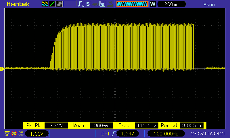
...My code already contains a very short, interruptible delay (5ms) which creates a pretty good (slightly jittery) 100Hz signal on the selected pin.
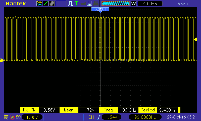
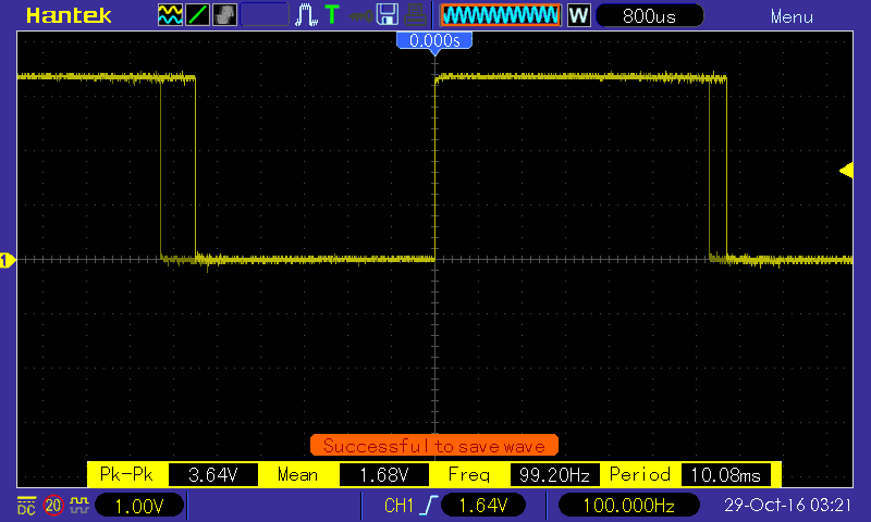
Jitter is not a problem here. At least I have an approximate frequency range so I can tune the rest of the circuit.
Now, the hardware.
I checked the program's behaviour with the scope then proceeded to assemble the charge pump.
I used the same part as the following schematic:
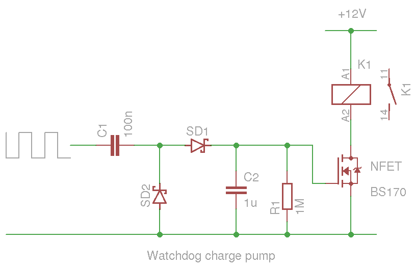
The discharge time constant is approximately 1µ×1M=1s. This means that the same charge as C2 should be reinjected several times per second, to keep its nominal voltage.
C1 is chosen smaller to reduce the strain/current on the GPIO pin, and also because at least 10 cycles are needed to charge C2. Actually it's more like 30 to reach a good voltage, so 30Hz is like a minimum frequency. I have a 3:1 margin, that's good. The CPU can miss a few beats, and the relay has some hysteresis so the whole will not oscillate wildly in case of high CPU load.
For the beginner, the interesting trick is that the ratio of capacity between C1 and C2 deternmines the speed of rising voltage. It's also influenced by the signal frequency. A larger C1 will charge C2 faster but also create higher currents. A higher input frequency requires a smaller capacitor.
Discharge curve:
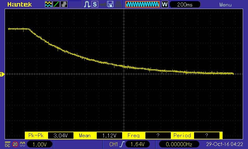
The discharge is slow and no freewheel diode is required for the relay :-)
Charge curve:
As expected, 10 cycles bring the level to 2/3Vcc (2V). At 30 cycles, it's "almost there".
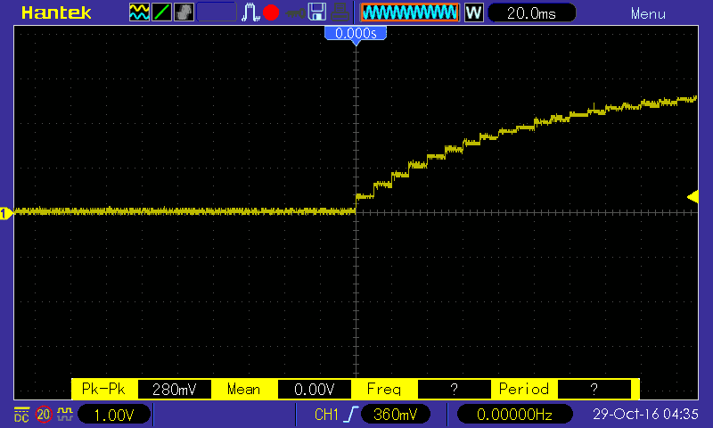
The curve at the intermediary node:
Now the only problem is that the BS170 barely lets current flow at Vgs=2.90.
I have used BAT85 (small signal Schottky diodes) to minimize the losses but this is yet not enough. The BS170 would rather have 3.3V or 5V to switcth the required 65mA with the least losses possible.
(Note: "just for safety" I left the freewheel diode from the previous iterations of the board, which has seen some serious work already)
The normal solution is to wire 2 more diodes and capacitors to double the charge pump's voltage:

But space was too tight so I used the other solution: get a better transistor. I could have some use for @DeepSOIC's depletion trick but he saw that the effect doesn't last :-P
I settled for a SI4920 (double N-MOSFET in SOIC-8) that was waiting in a drawer. The behaviour is better but in case of inactivity, this leaves only 1/2s until the relay is released again.
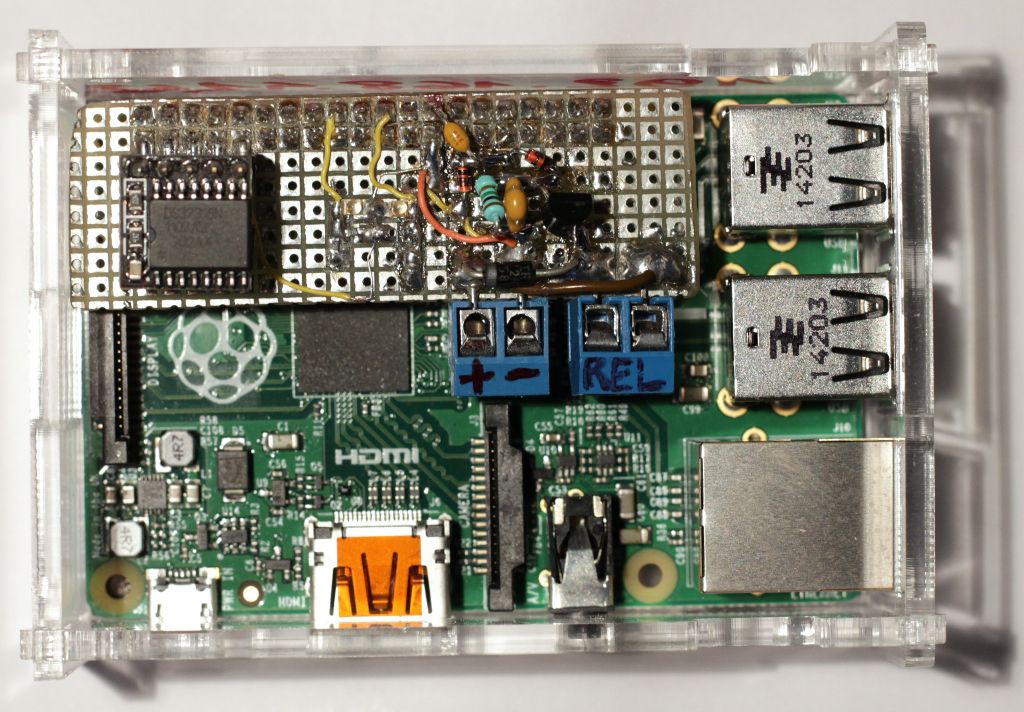
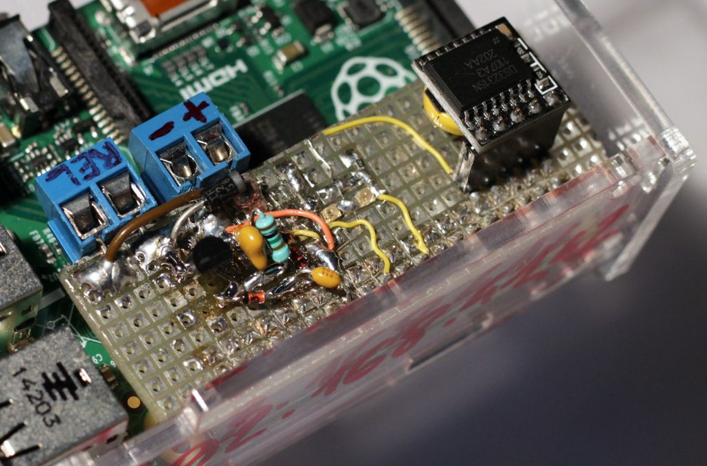
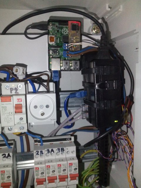
With the new transistor (and after a few tests) I installed the board in the definitive control box.
Come near the Stade de France in Saint Denis and see it at work ;-)
Discussions
Become a Hackaday.io Member
Create an account to leave a comment. Already have an account? Log In.
Oh and nobody notices my new (clumsy) toy that exports screenshots so I don't have to waste my time editing photographs of a phosphor screen ? :-D
Are you sure? yes | no
Yann, did you get a digital scope? Finally come over to the "dark side," have you?
(As I say this, I notice my avatar is on an analog scope...)
Are you sure? yes | no
Not for "critical designs" ;-)
It's handy for many mundane tasks and next time I'd probably get a Rigol for the Ethernet port, but so far, it's very nice to play with the kids during the workshop, and document basic slow circuits like this one.
Are you sure? yes | no
Yes, I like the USB screenshot convenience, too. One of my Rigols (DS2072 with 300MHz "upgrade") formats images with some bad header or something, so hackaday.io won't accept them as-is. I need to open them in gimp and re-save before I can upload. Other than that, it's almost as good as the analog scope I always wanted.
Which Hantek did you get?
Are you sure? yes | no
see at the bottom of the page: DSO5202P (not hacked), with atching probes, about 330$ from China
For more demanding designs, I have the 4×300MHz Tek 2465 but I don't have enough probes (ordered some but they vanished in transit ?)
Are you sure? yes | no
The DSO5202P looks like a pretty good deal based on the specs, but now I have to stop looking at it - I'm a scope addict. I was up to seven, but I sold one, gave one away, and one needs repair (in other words it doesn't work, but I'm keeping it around anyway). I'll get in trouble if another one appears on my doorstep...
Are you sure? yes | no
I feel your pain.
Are you sure? yes | no
So, how yah gonna power it up? Hold a pushbutton across the relay contacts until the charge-pump reaches its threshold?
Are you sure? yes | no
The Pi has its own power supply.
It controls an external "public service" that is turned off when my program does its job :-)
Are you sure? yes | no
ah, so the dead-man's switch isn't killing power to the Pi, but to what it's connected...
Nice job on screen-capture, I take it. Dunno the functionality of Hantek 'scopes ;)
Are you sure? yes | no
No, it is only disabling some safety lights that interfer with the art piece.
I got a DSO5202P and the interface is not "intuitive" but I slowly learn how to use it...
Are you sure? yes | no