Close
0%
0%

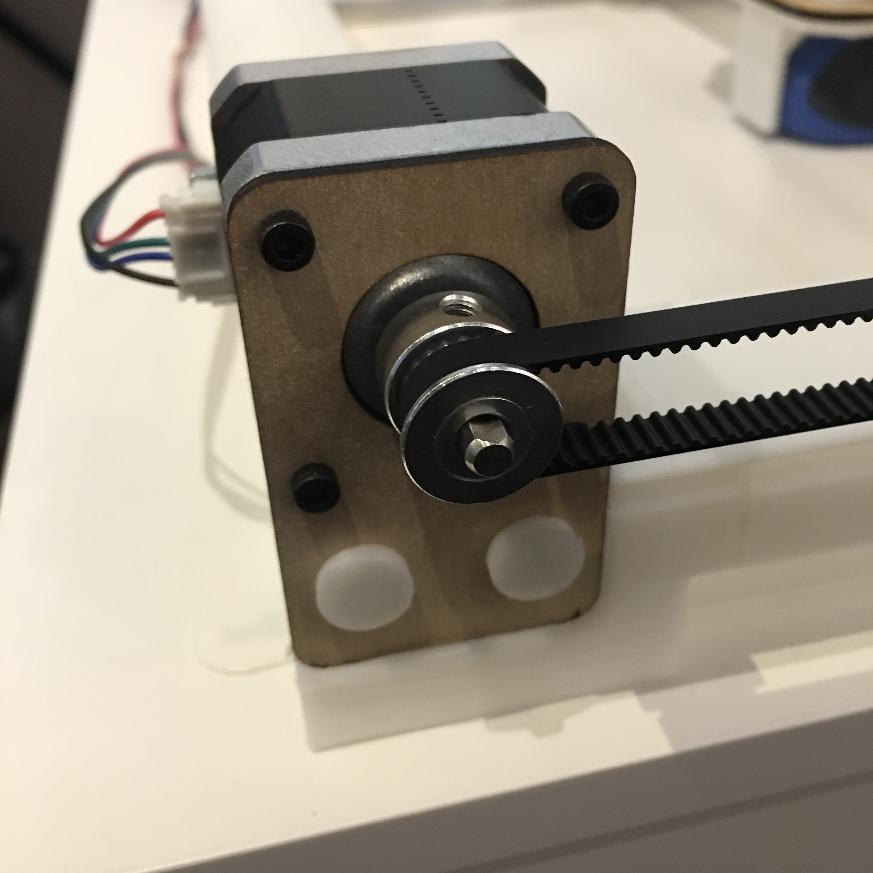
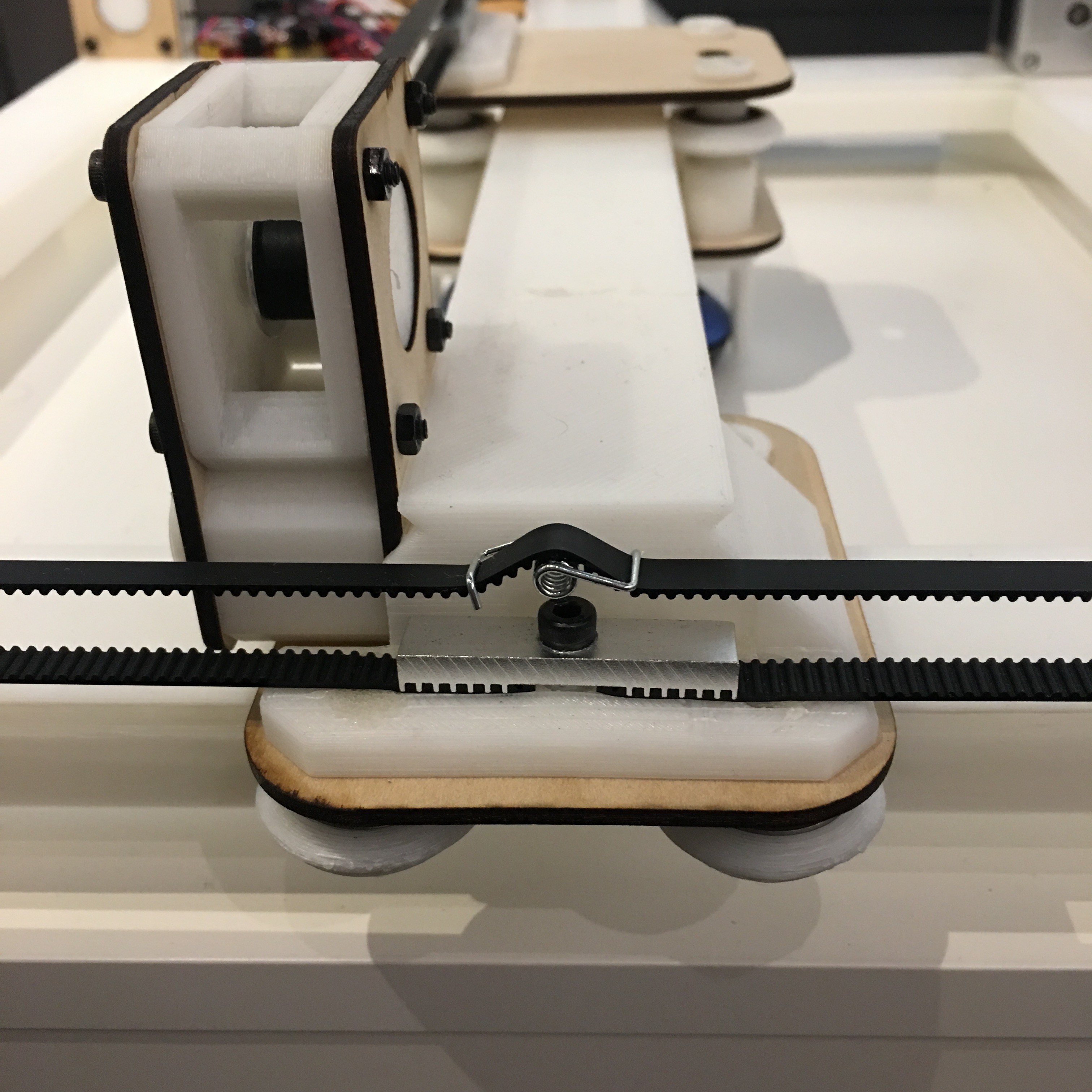
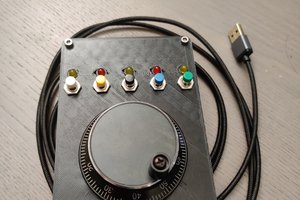
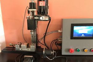
Mouse Controlled Mouse Controller

This is a controller that uses a mouse to control an XY gantry that controls a mouse.

Public Chat
Similar projects worth following
This machine has no purpose. It's a useless machine. When I heard about the Macrofab design contest. I thought this would be a perfect opportunity to make something that no one else would make, and to learn a couple of things that I’ve been interested in.

The mouse controller consist of a mouse that is connected to a Raspberry Pi. The Raspberry Pi converts the position of the mouse to G-code commands with a python script. The G-code commands are sent to an Arduino through USB. The Arduino is programmed with GRBL and is fitted with CNC controller shield. The Arduino CNC controller drives 3 stepper motors that control a 3D printed and laser cut XY gantry. The XY gantry moves a mouse.


parts list.xlsx

3D printed, laser cut and purchased parts

Microsoft Office - OOXML - Spreadsheet - 12.42 kB - 08/09/2019 at 22:10

Download

3D printed and laser cut parts.zip

STL and DXF files for 3D printing and laser cut parts

x-zip-compressed - 270.16 kB - 08/08/2019 at 11:43

Download

mousecontroller.py

Python script for converting mouse position to G-code and sending it to the CNC controller

py - 446.00 bytes - 08/08/2019 at 11:43

Download

GRBL settings.txt

CNC controller settings.

plain - 1016.00 bytes - 08/08/2019 at 11:43

Download

View all 39 components

  • 1
    Building the XY Gantry

    Included in this post are the STL and DXF files needed to 3D print and laser cut the gantry.  STL files of the laser cut parts are also included in case a laser cutter is not available.  The STL and DXF files can also be downloaded from Thingiverse.  I have included the link below.

    https://www.thingiverse.com/thing:3799000

    I've also included a parts list, which includes the quantities needed for the 3d printed and laser cut parts, and a list of purchased parts and sources.

    The Fusion360 design file for the XY gantry can be found in the link below.  This can be used for determine parts placement for the 3D printed and laser cut parts.

    https://myhub.autodesk360.com/ue2d8bc19/g/shares/SH56a43QTfd62c1cd9687e9feca593e75dfb

    For this project I glued all of the mating 3D printed part together.  Since I printed this with ABS I was able to make glue using acetone and failed prints.  Super glue or Bob Smith will also work.

    After the 3D printed and laser cut parts were assembled the motors and belt drives were mounted.  The motors were bolted to the motor mounts using  the M3x6mm screws.  The idler pulley shafts I bought were to long and need to be cut down to 20mm.  The idler pulley assembly was put together using the M3x30mm screws and nuts.  The belts were cut to length and clamped using the M4x20mm  screws and gear clamp belt clamps.  The spring tensioners were added to the center belt.  

  • 2
    Programming the CNC Controller

    The CNC controller was programmed with GRBL.  The github link for GRBL can be found below.  

    https://github.com/grbl/grbl

    I have also included my GRBL settings below, and a tutorial I used to figure out how to configure the settings.

    https://github.com/gnea/grbl/wiki/Grbl-v1.1-Configuration

    $0=10 (step pulse, usec)
    $1=25 (step idle delay, msec)
    $2=0 (step port invert mask:00000000)
    $3=0 (dir port invert mask:00000000)
    $4=0 (step enable invert, bool)
    $5=0 (limit pins invert, bool)
    $6=0 (probe pin invert, bool)
    $10=3 (status report mask:00000011)
    $11=1.000 (junction deviation, mm)
    $12=0.025 (arc tolerance, mm)
    $13=0 (report inches, bool)
    $20=0 (soft limits, bool)
    $21=0 (hard limits, bool)
    $22=0 (homing cycle, bool)
    $23=0 (homing dir invert mask:00000000)
    $24=25.000 (homing feed, mm/min)
    $25=500.000 (homing seek, mm/min)
    $26=250 (homing debounce, msec)
    $27=1.000 (homing pull-off, mm)
    $100=20.000 (x, step/mm)
    $101=20.000 (y, step/mm)
    $102=20.000 (z, step/mm)
    $110=125000.000 (x max rate, mm/min)
    $111=125000.000 (y max rate, mm/min)
    $112=125000.000 (z max rate, mm/min)
    $120=1500.000 (x accel, mm/sec^2)
    $121=1500.000 (y accel, mm/sec^2)
    $122=1500.000 (z accel, mm/sec^2)
    $130=200.000 (x max travel, mm)
    $131=200.000 (y max travel, mm)
    $132=200.000 (z max travel, mm)

  • 3
    Setting up the CNC controller

    Below are photographs of the CNC controller shield.  These can be used to determine jumper position, wiring, and stepper driver orientation.  

    For the stepper motors I used I set the drives up for 1/4 step.  This can be set using the jumpers positioned below each of the three large capacitors.  Note that only the middle jumper is set. 

    Since the y-axis has two steppers I used driver A to drive the second motor.  This is done by adding the two jumpers on the left to the y-position.  Since the two y-axis steppers need to spin in opposite directions, I wire one of the steppers backwards.  Note the wire color pattern for driver Y and A.  

    Note the location of the potentiometers 

View all 5 instructions

Enjoy this project?

Share

Discussions

6hercilio.silvadw wrote 09/24/2021 at 11:02 point

What an amazing post really its a nice idea to controll the mouse and you can check its speed by visiting easycpstest website.

  Are you sure? yes | no

scott wrote 10/11/2020 at 00:22 point

What a well documented project.  I actually have a possible use for the main parts of it, controlling a stepper with a mouse, so thank you.   I've got a lot of electronic experience, I've fiddled with a Raspberry Pi for 3D Printing (Octoprint), have some long time Linux system admin skills, and I build a small CNC router using Geko drivers.  But Arduino and Python are new to me.  I'm going to give it a shot.

  Are you sure? yes | no

Carl Smith wrote 09/12/2019 at 17:18 point

Have you tried attaching the controlling mouse to the mouse controller to see what kind of motion feedback you could create?  I imagine if you attached it in the same orientation and gave it a bump to start some motion it would just track to the edge and hit a side, but if you attached the controlling mouse in a different orientation maybe you could get it to chase itself around in a circle or something.   :)

  Are you sure? yes | no

[deleted]

[this comment has been deleted]

jeffreybernath wrote 09/07/2019 at 01:10 point

Thank you.

  Are you sure? yes | no

Similar Projects

Does this project spark your interest?

Become a member to follow this project and never miss any updates