 FiveseveN
Main development objectives:
- simplified construction: avoid the need for specialized tools and procedures;
- accessible materials: components should not be more exotic than generic hardware store stock; use previously sourced material whenever possible;
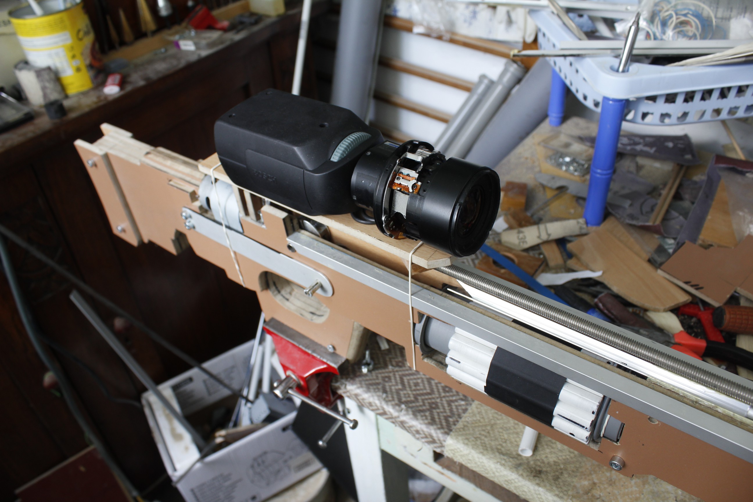
- specific features for use in residential areas at night: low noise and (active) night vision;
- the Rule of Cool must factor into every decision.
Surely the most thematically fitting type of weapon for such a purpose is a crossbow, and that was indeed the starting point for development: a modern compound crossbow enhanced with a Gauss gun module and of course equipped with IR-sensitive electronic scope and IR illuminator. This choice was based on, apart from the thematic evocation, one particular advantage of the crossbow-Gauss gun integration: the string provides a means to activate a mechanical contact that energizes the coil when the position of the projectile is known (right in front of the string).
A second choice had to be made when it became obvious that the proper material for the limbs would have to be a glass or carbon fiber composite, which was deemed to exotic and expensive. So the switch to a sling-bow configuration was made, where power is provided by the elasticity stored in rubber bands or coiled steel spring as an alternative. This change also allowed for a more compact design, free of protruding limbs.
In order to optimize the amount of power transferred from the elastic material, a lever system like the one used by compound (cross)bows was needed. A simple 2:1 pulley system was considered, based on tests published by user [rolynd] on The Arbalist Guild forum (link to thread). His results showed that pulley weight was critical, which could potentially lead to the same issue with exotic materials.
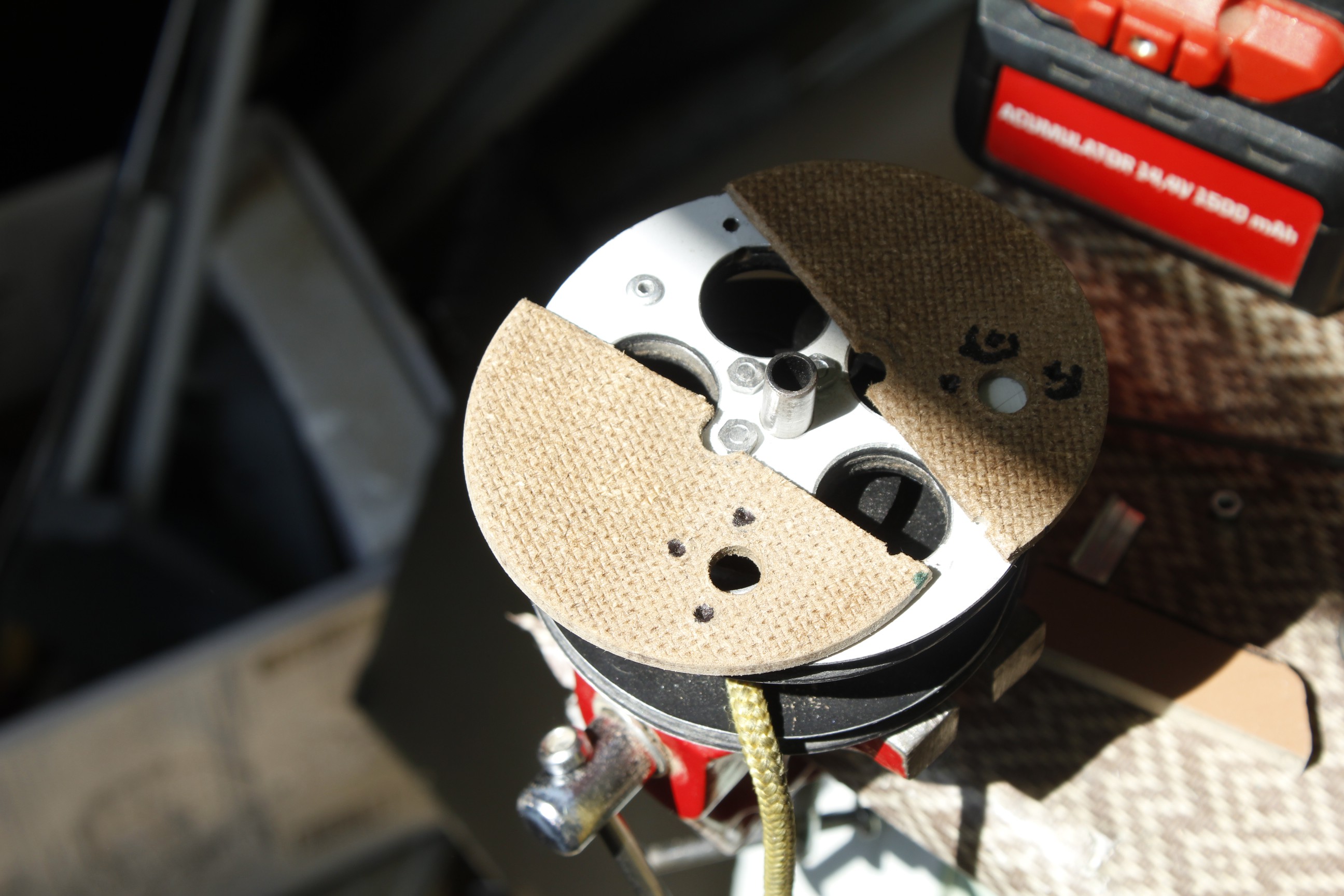
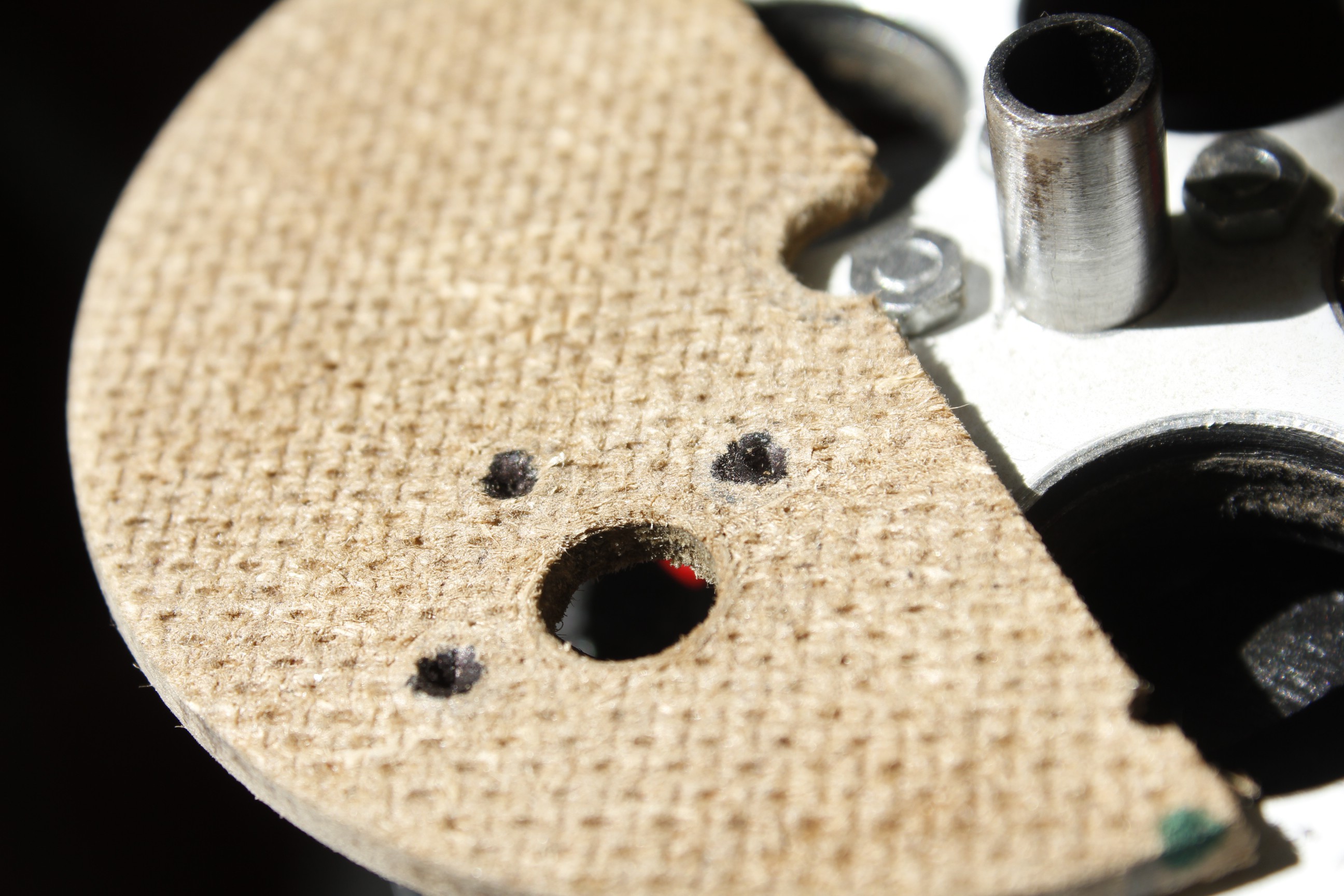
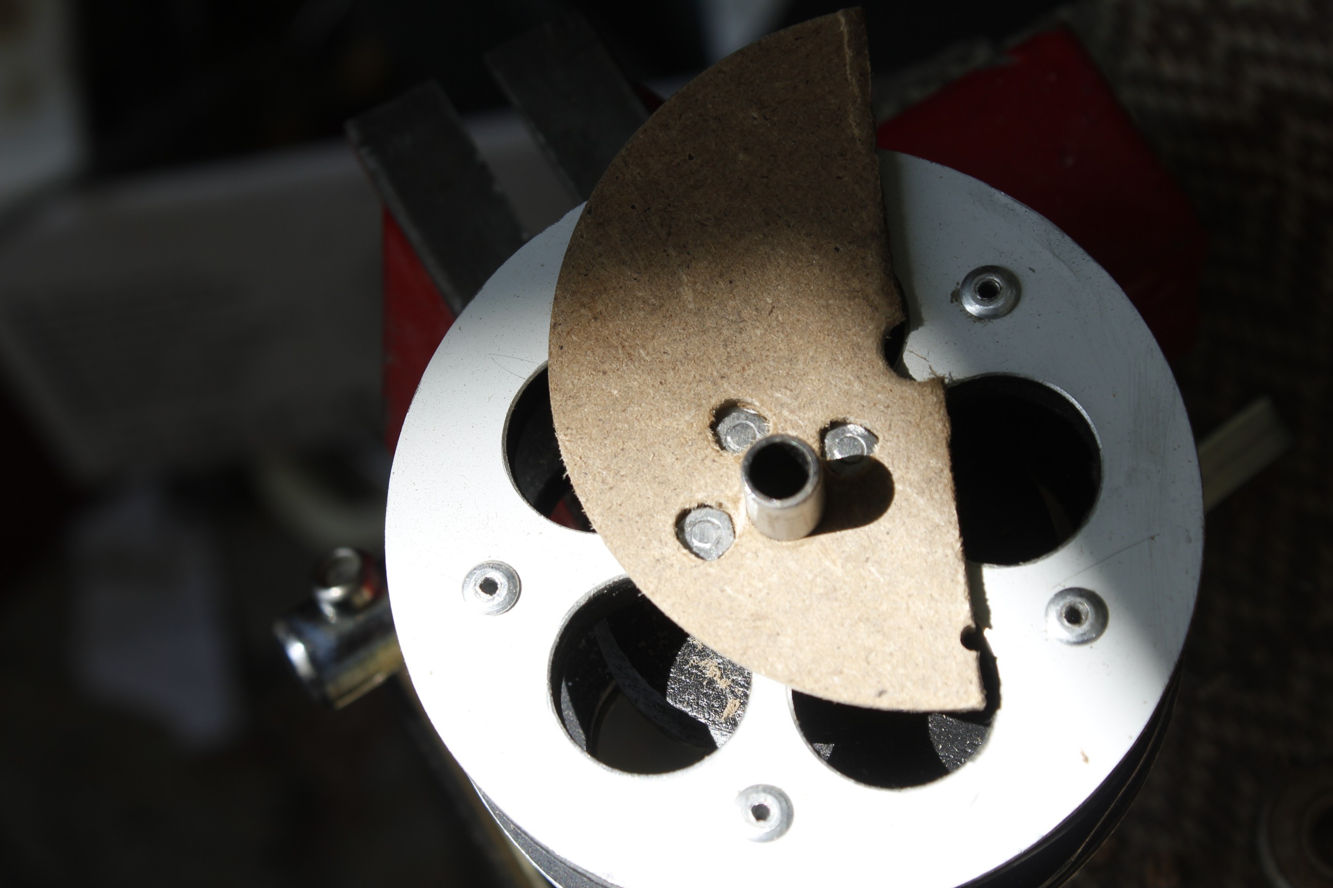
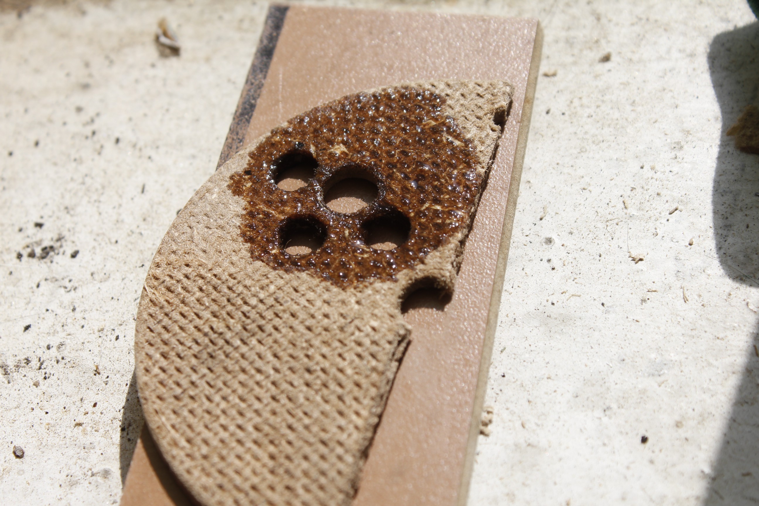
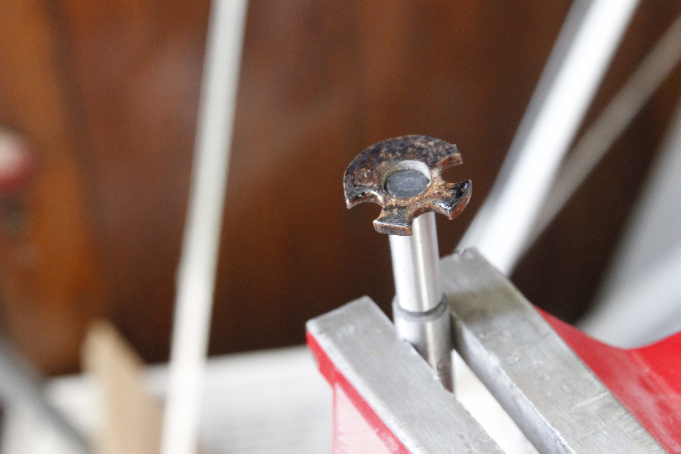
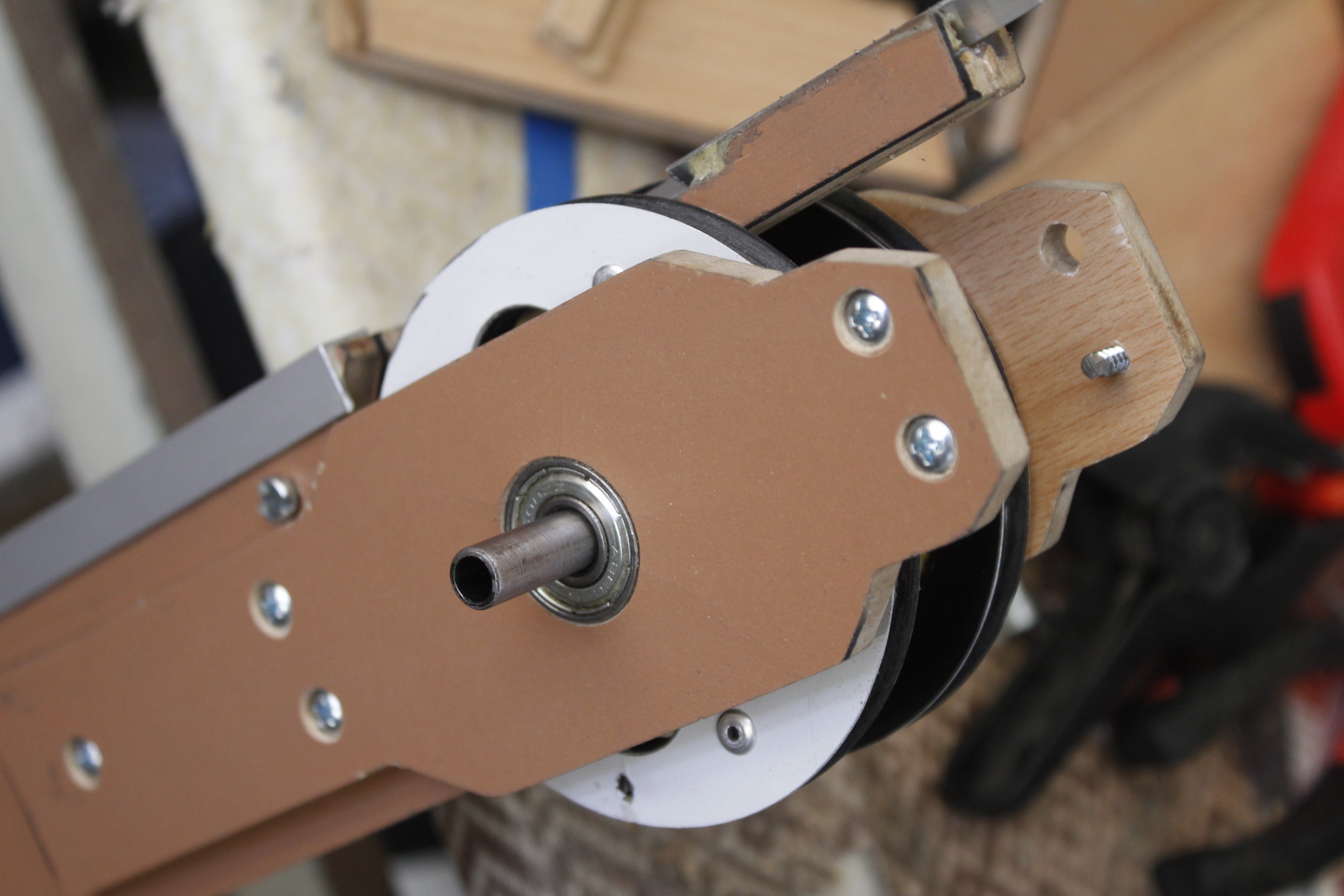
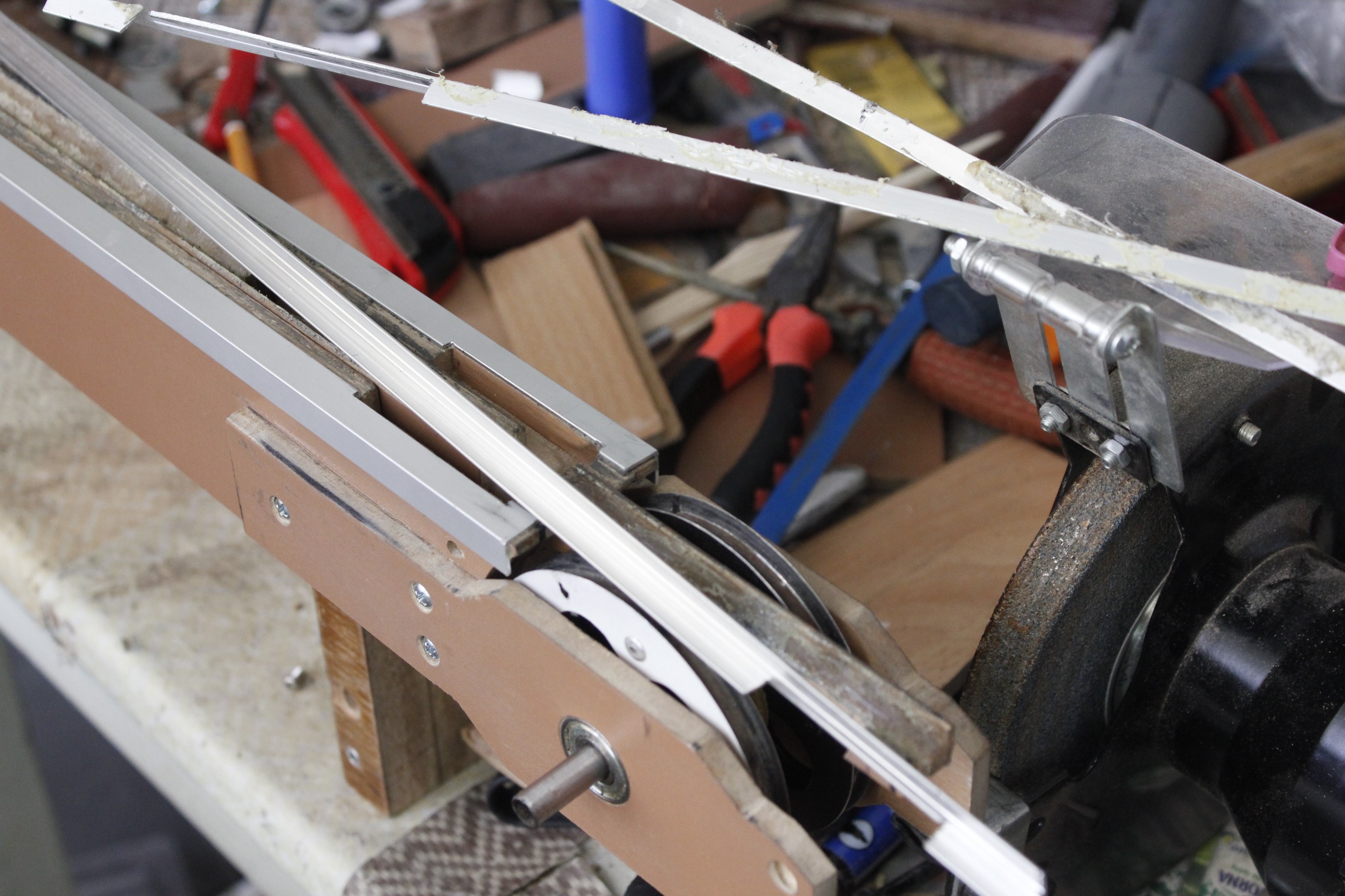
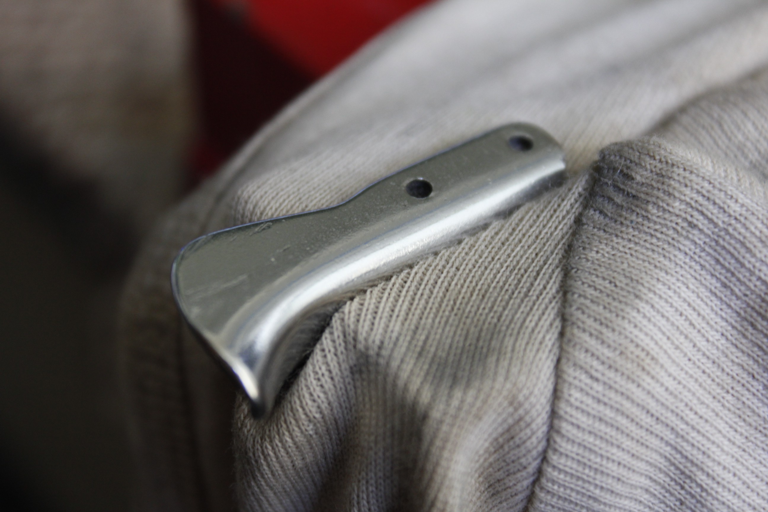
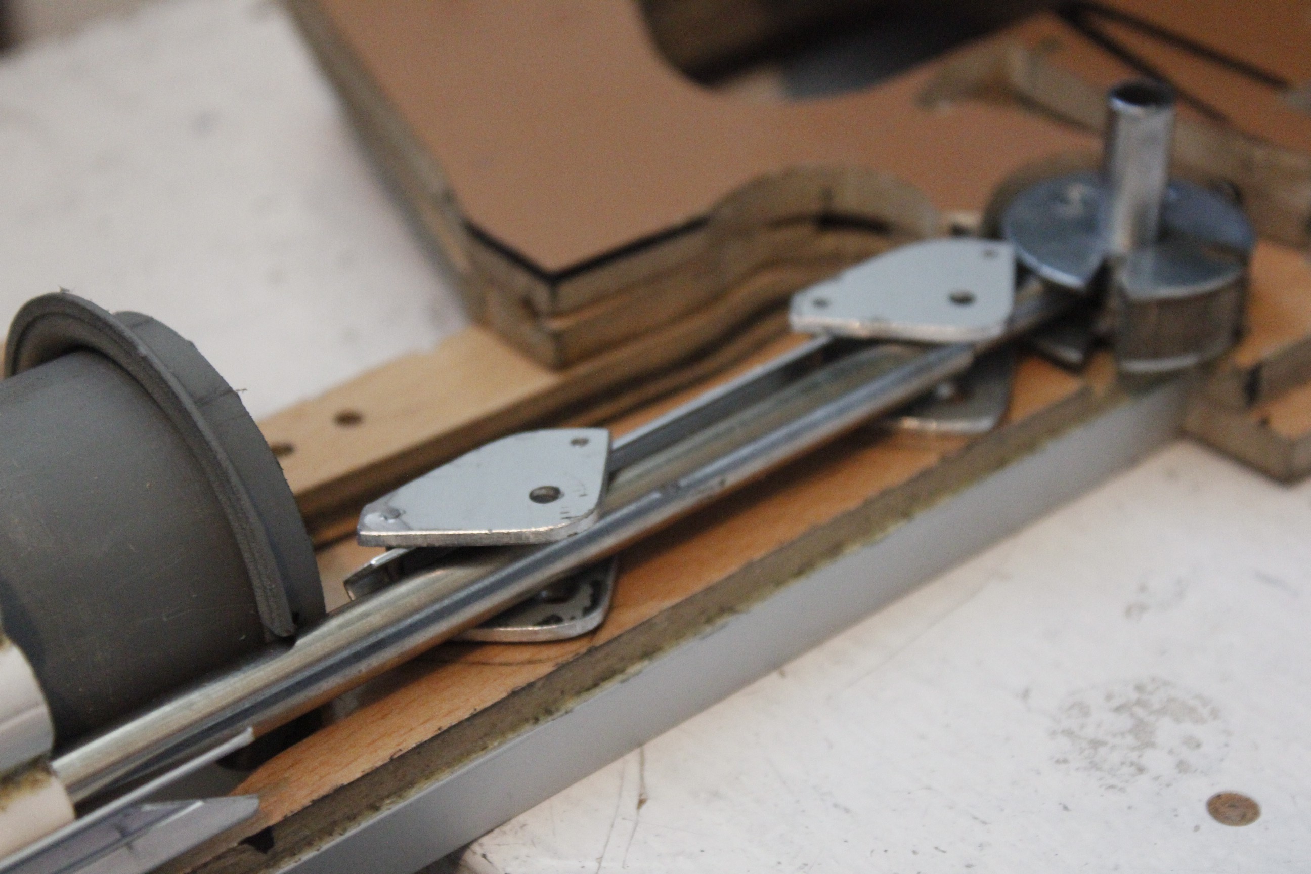
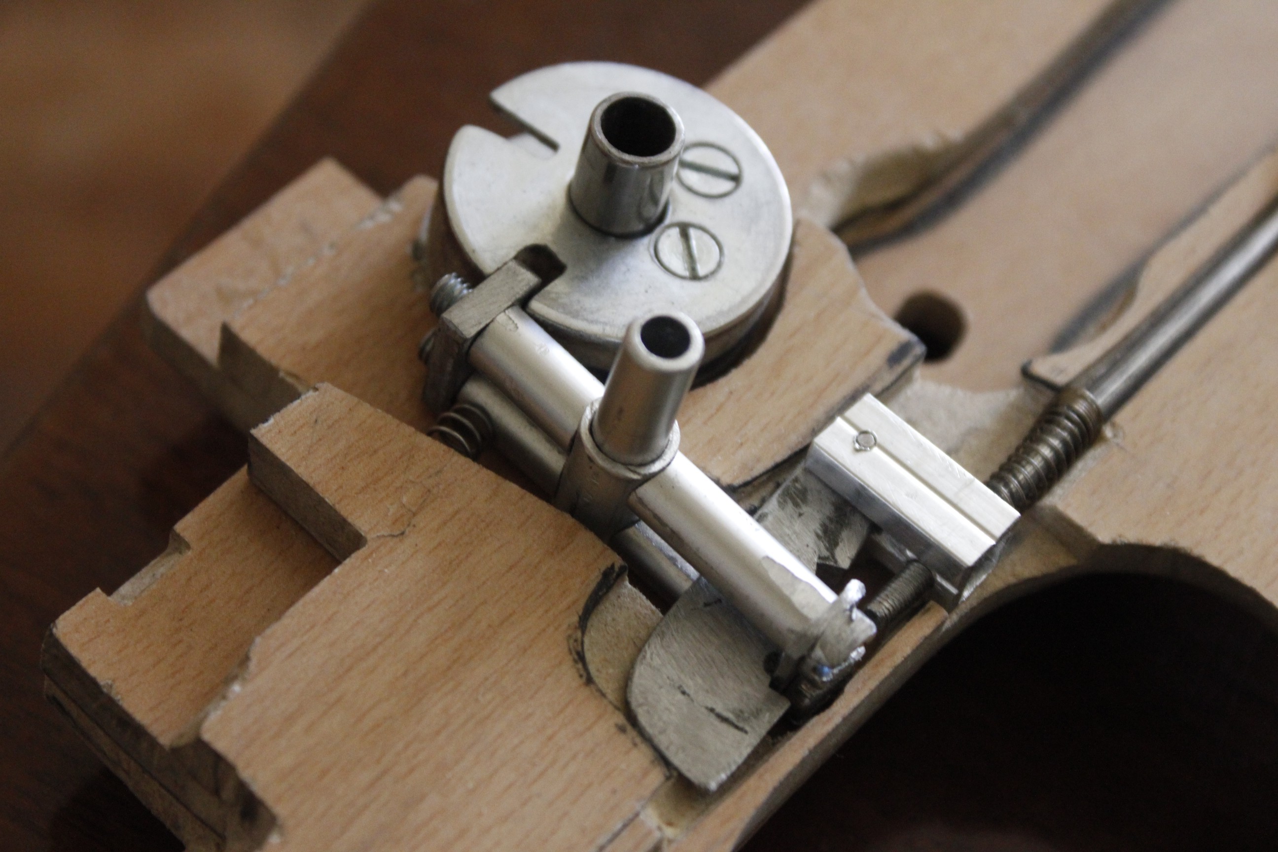
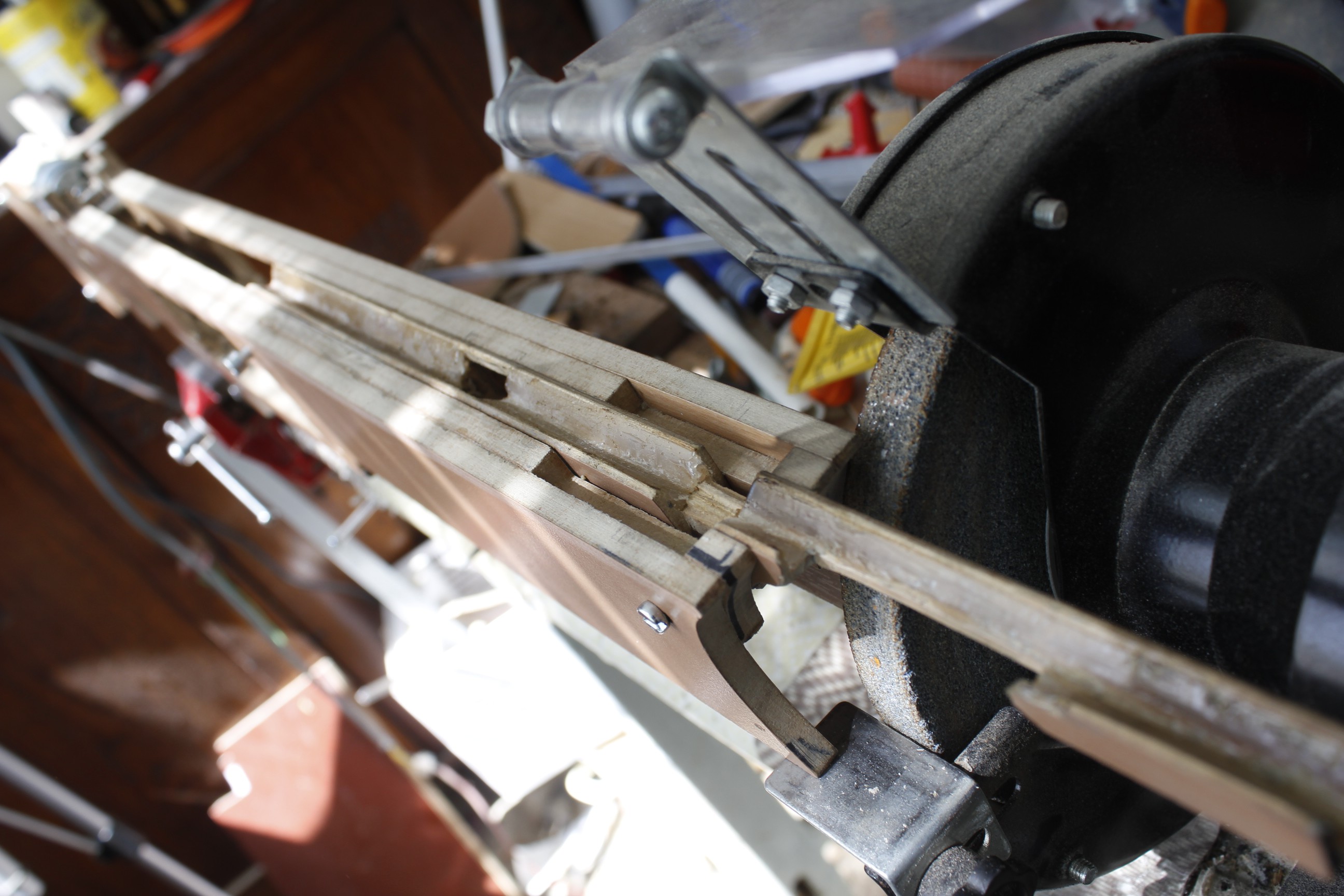
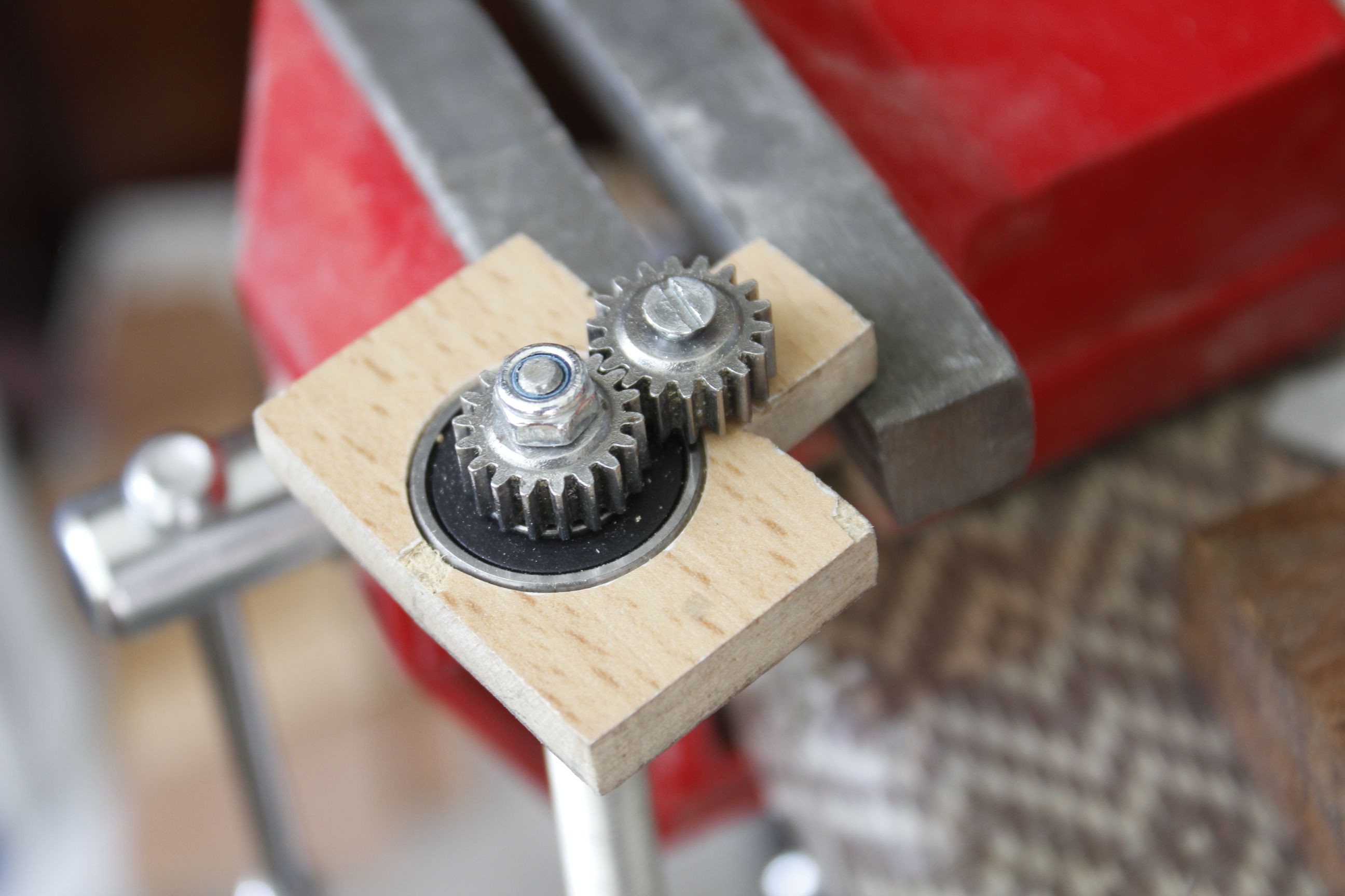
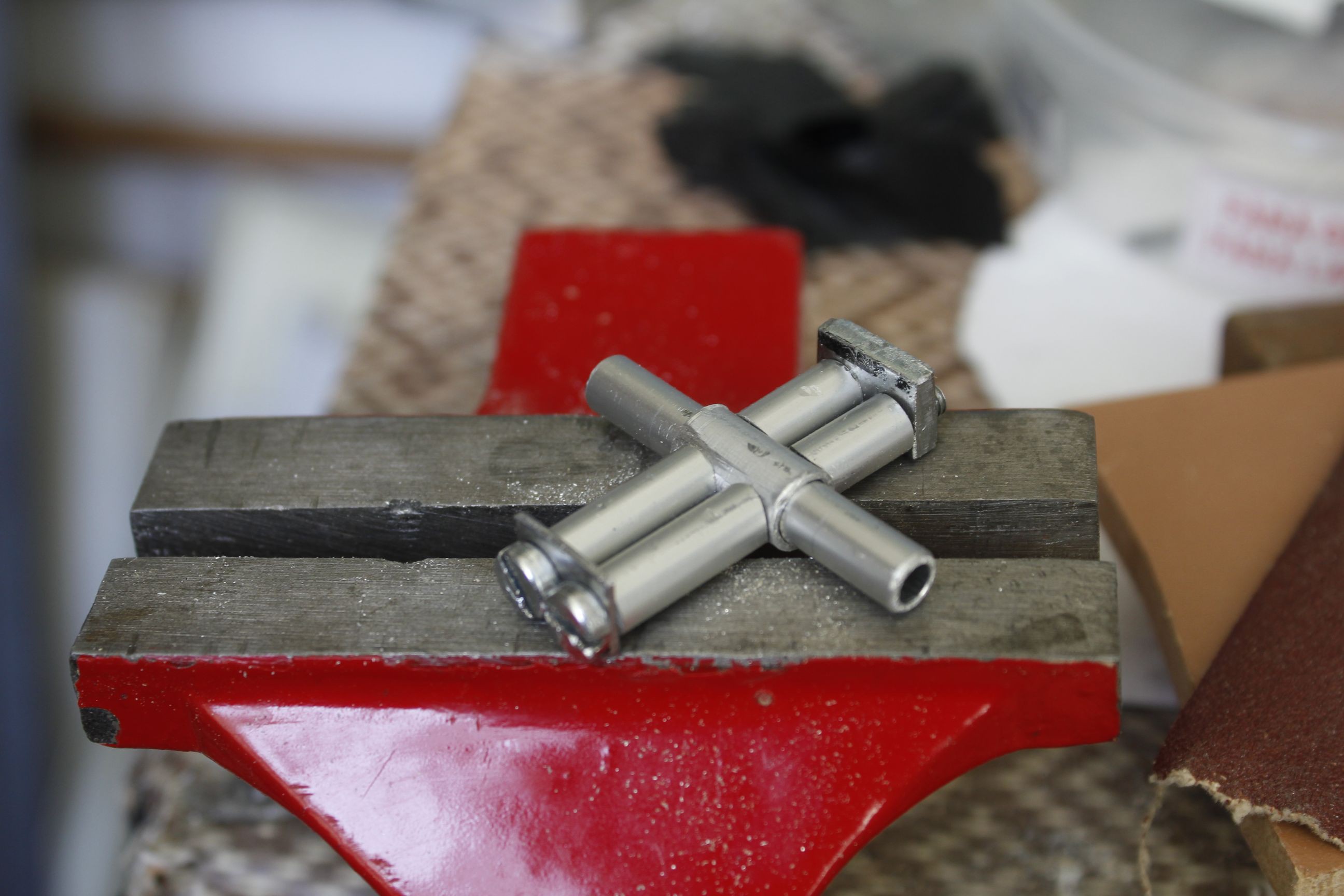
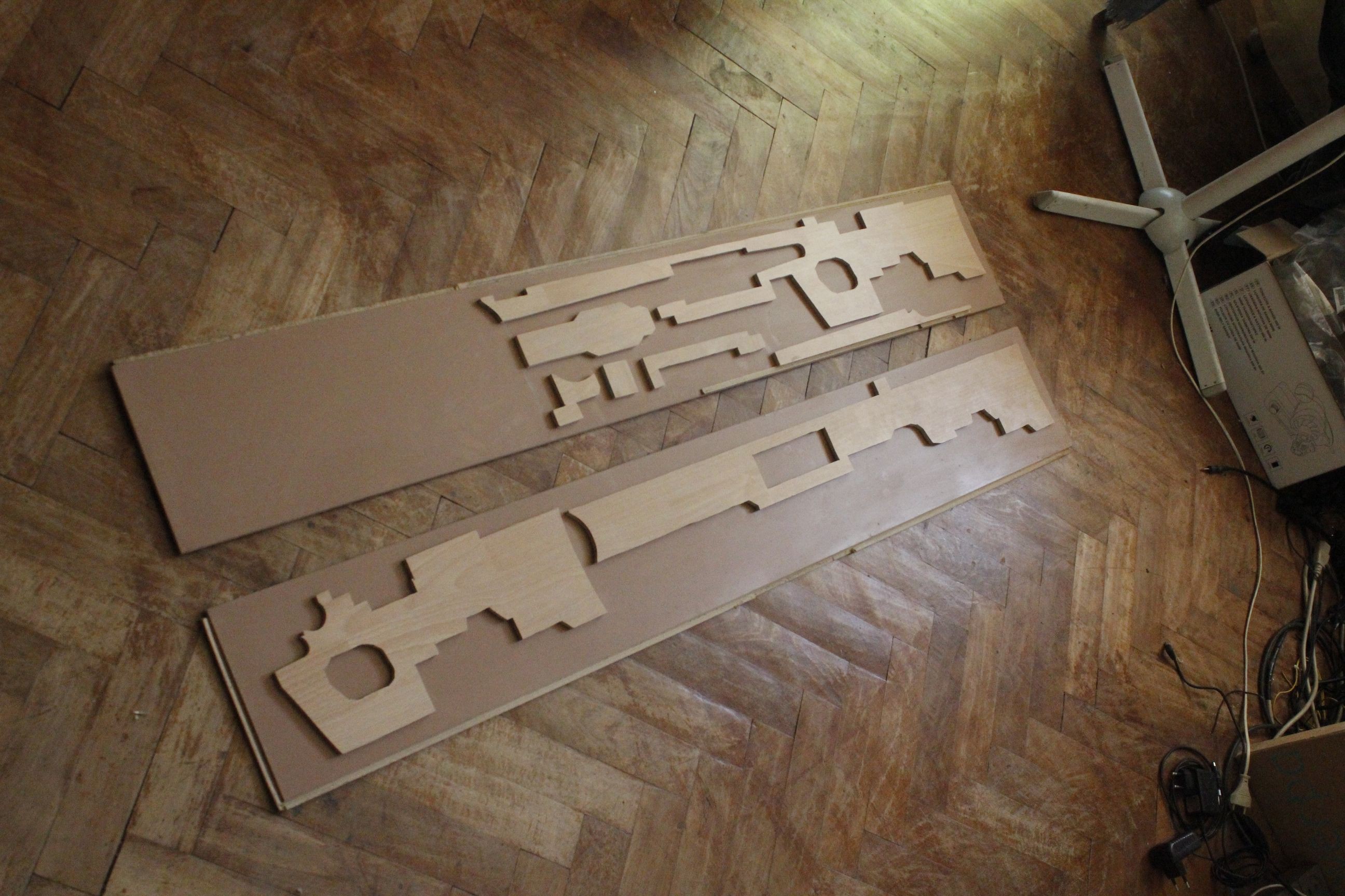
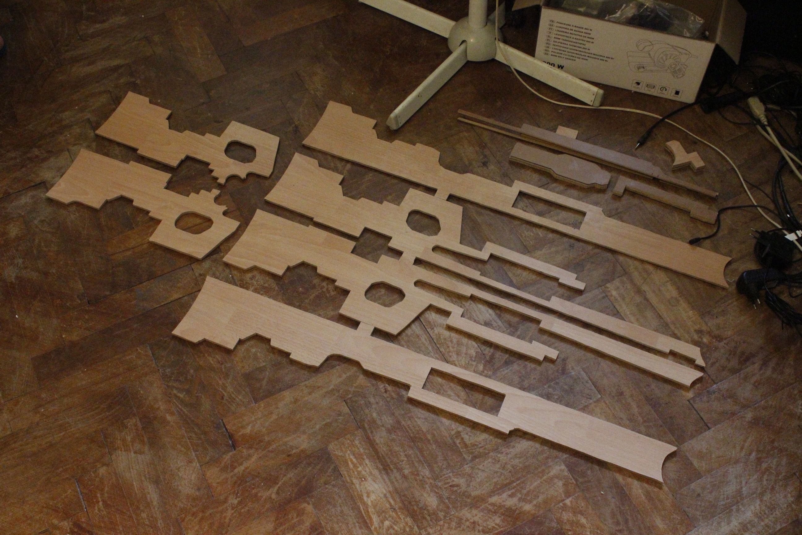
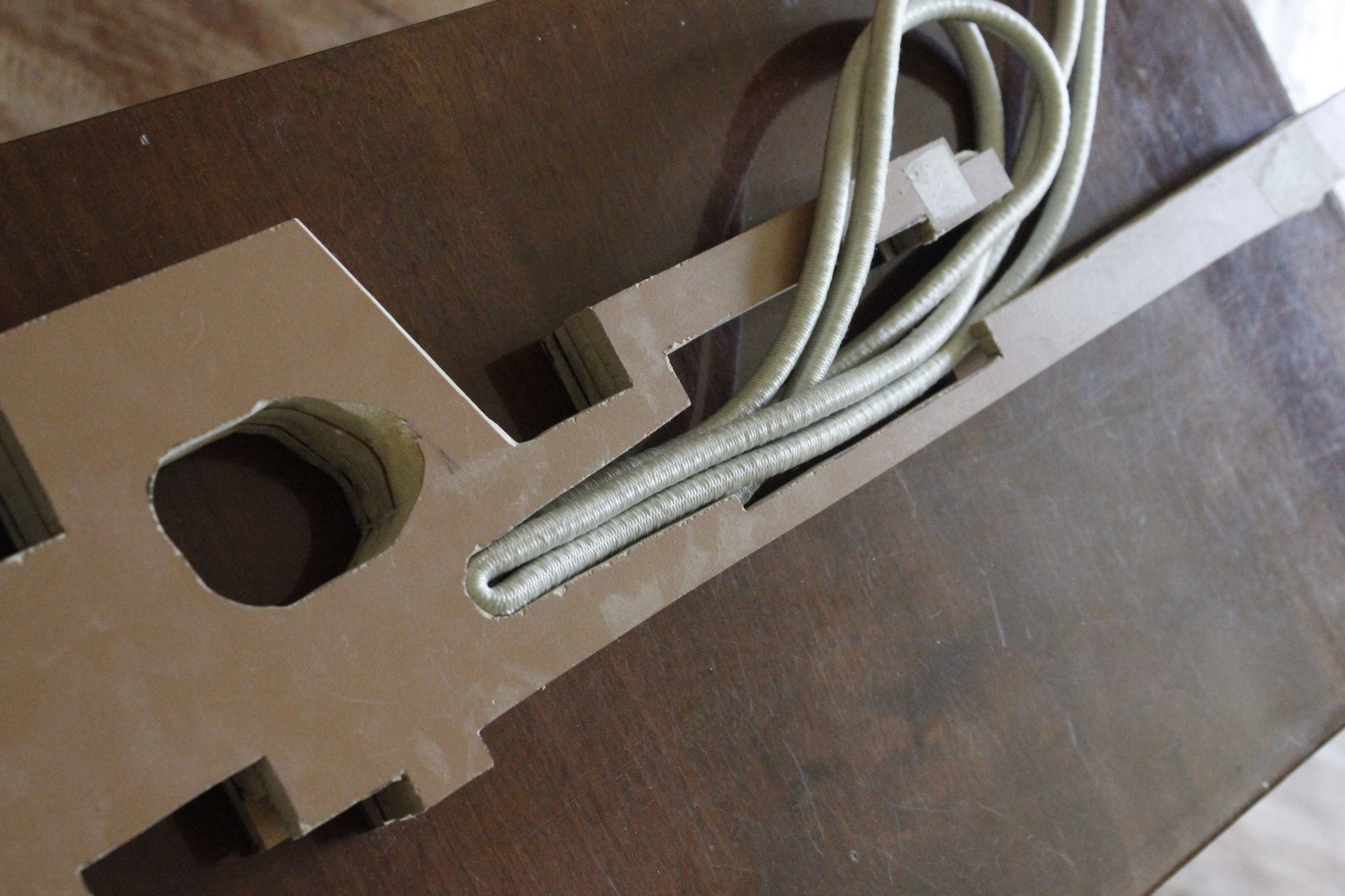
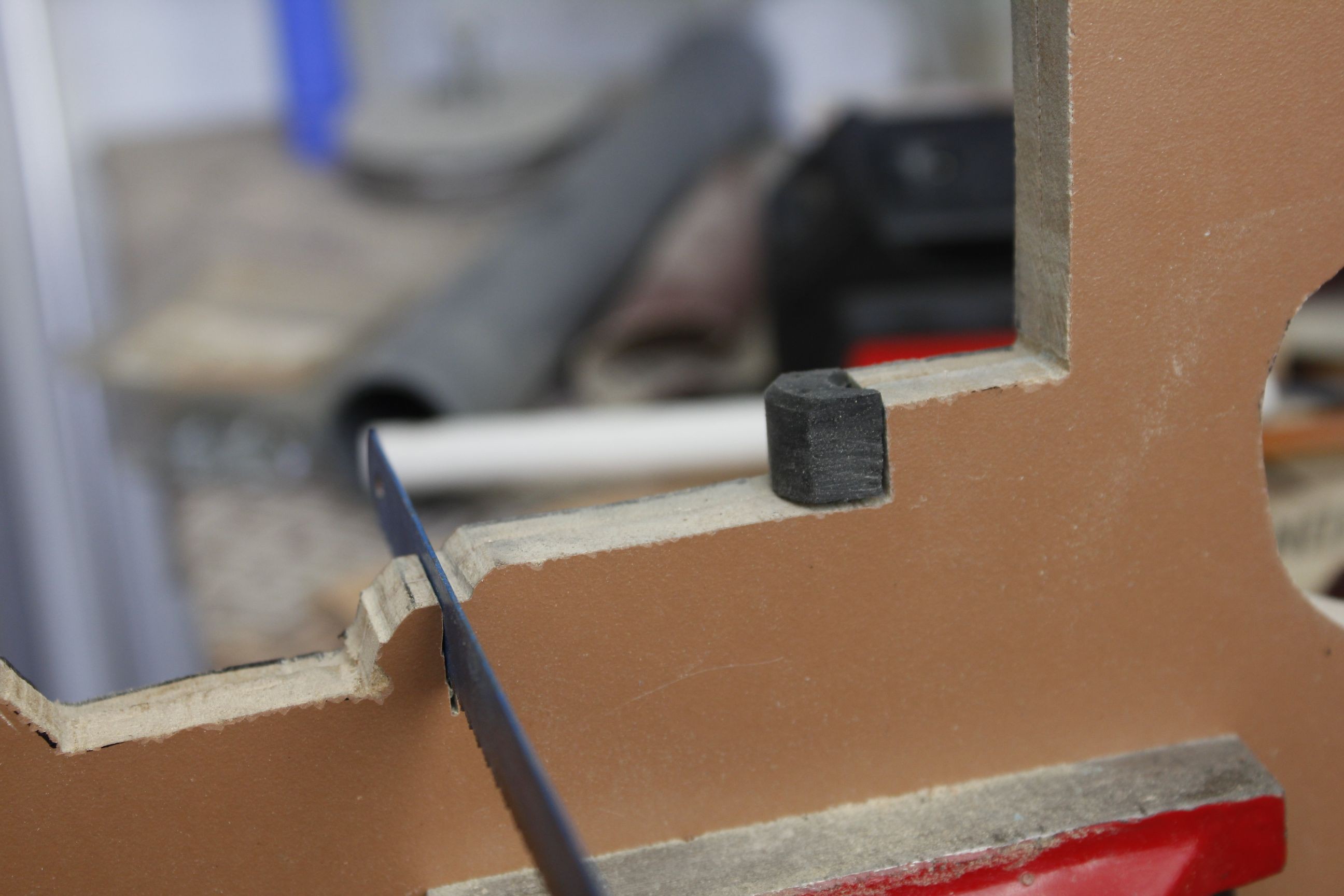
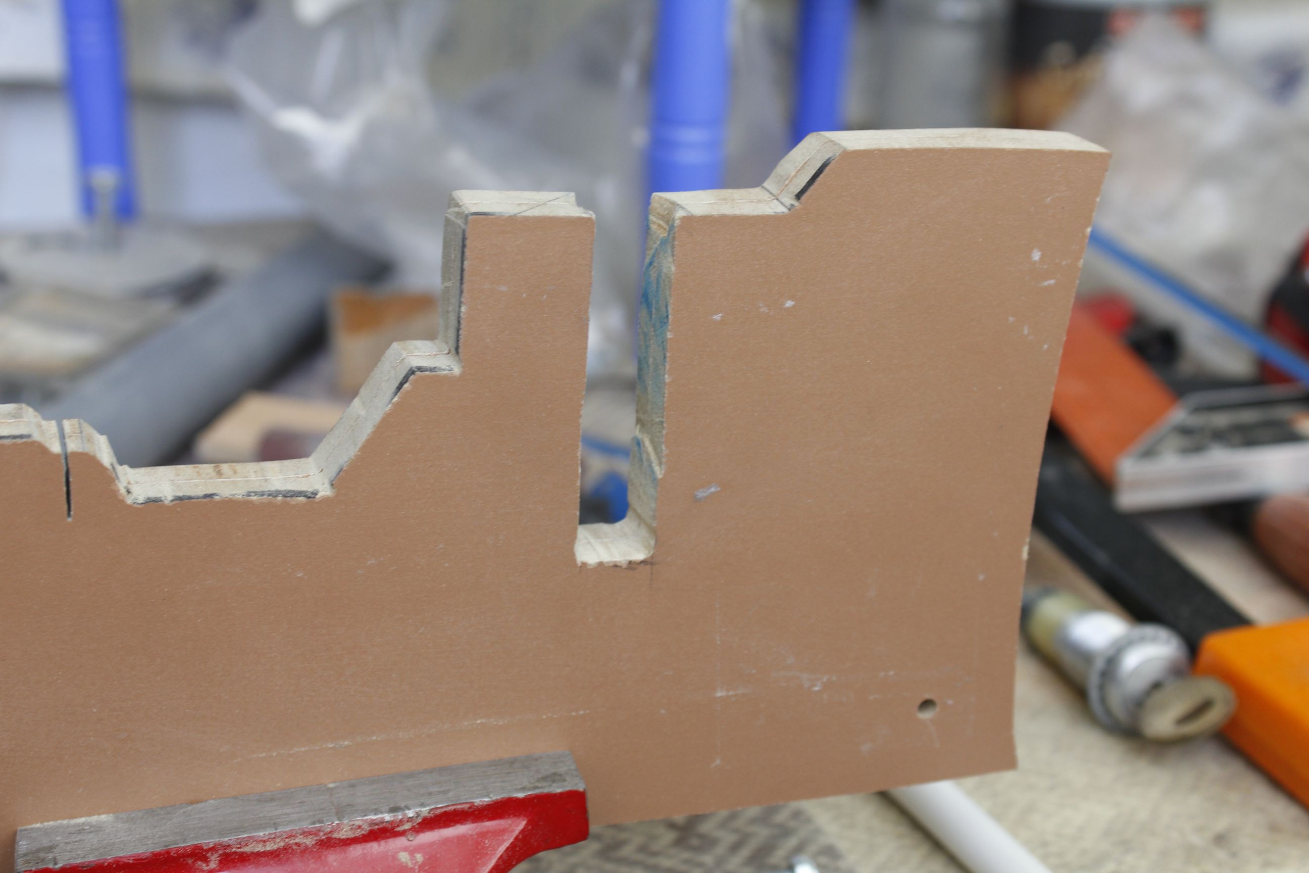
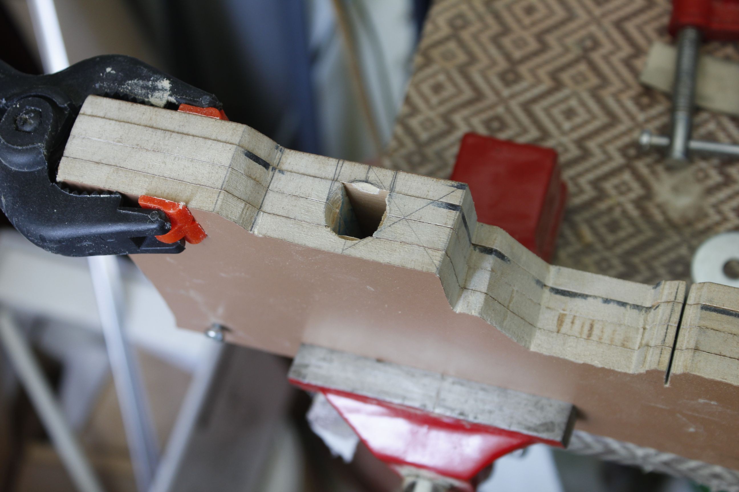
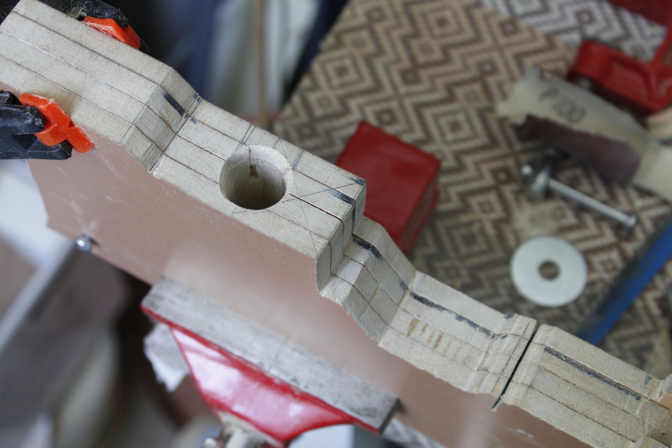
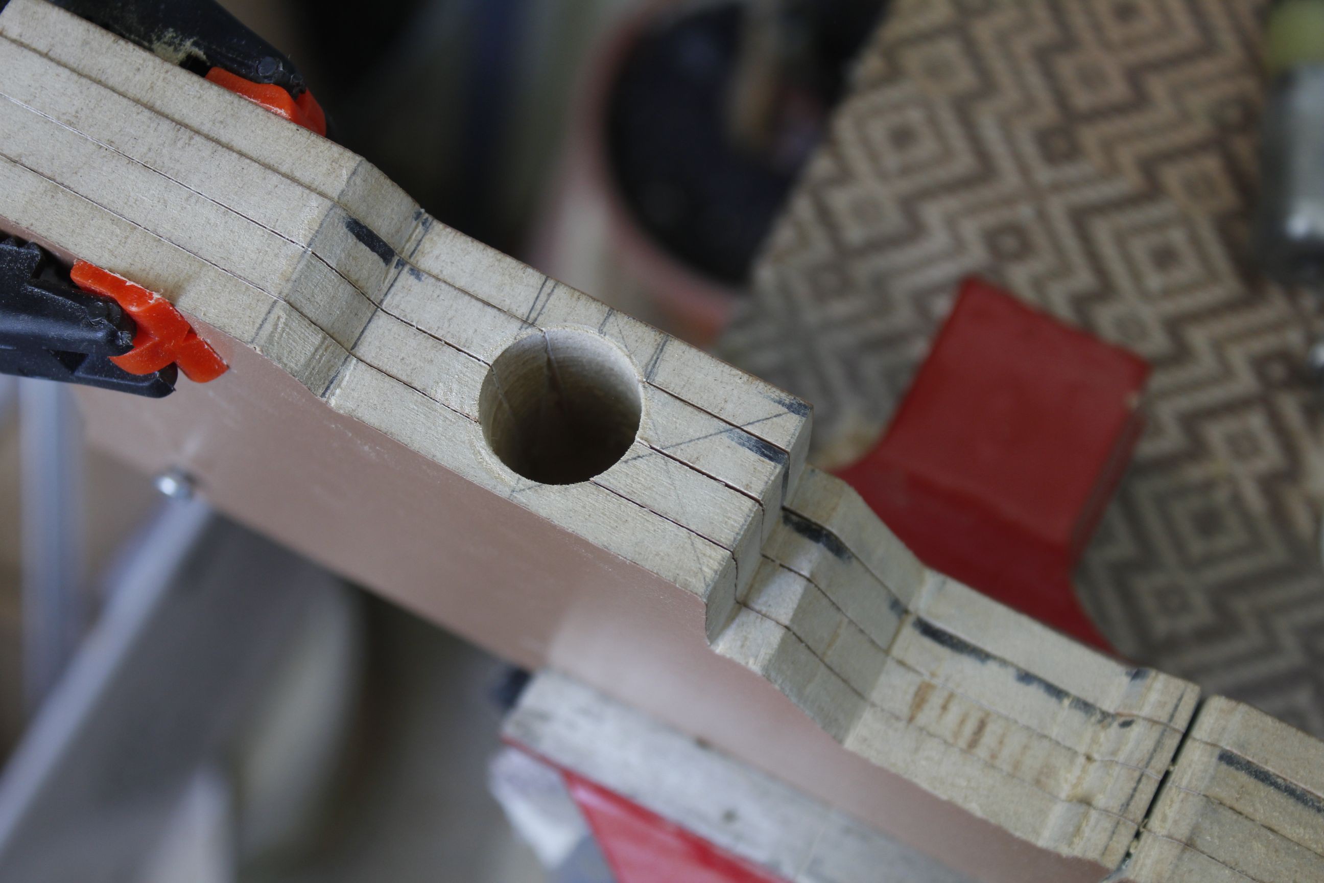
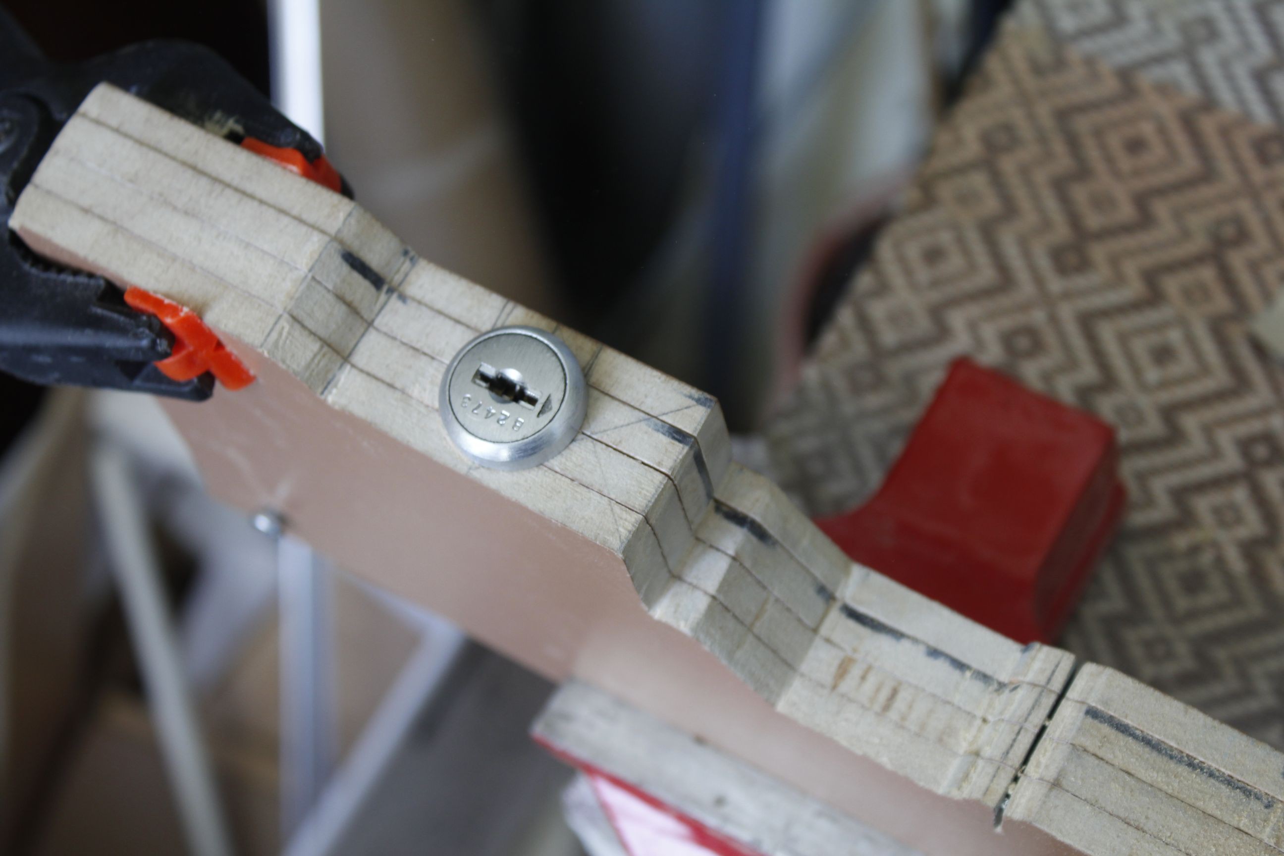
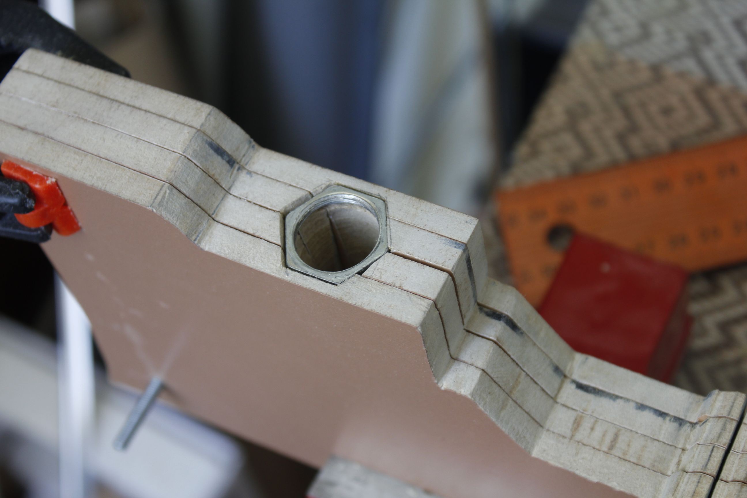
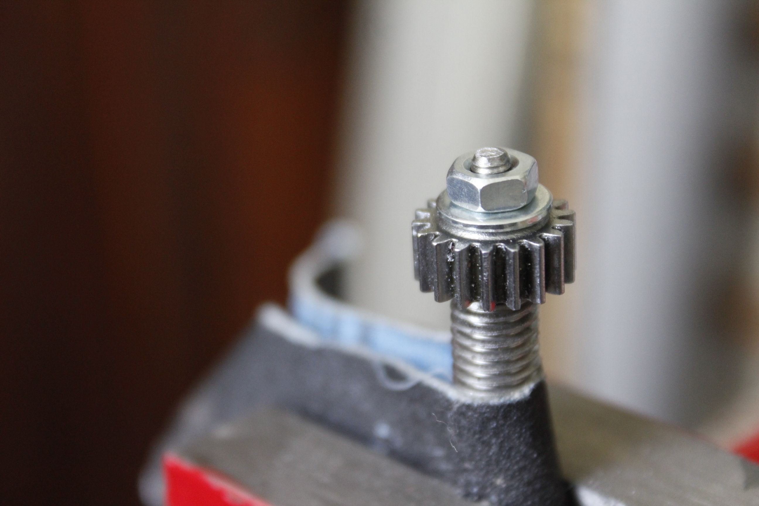
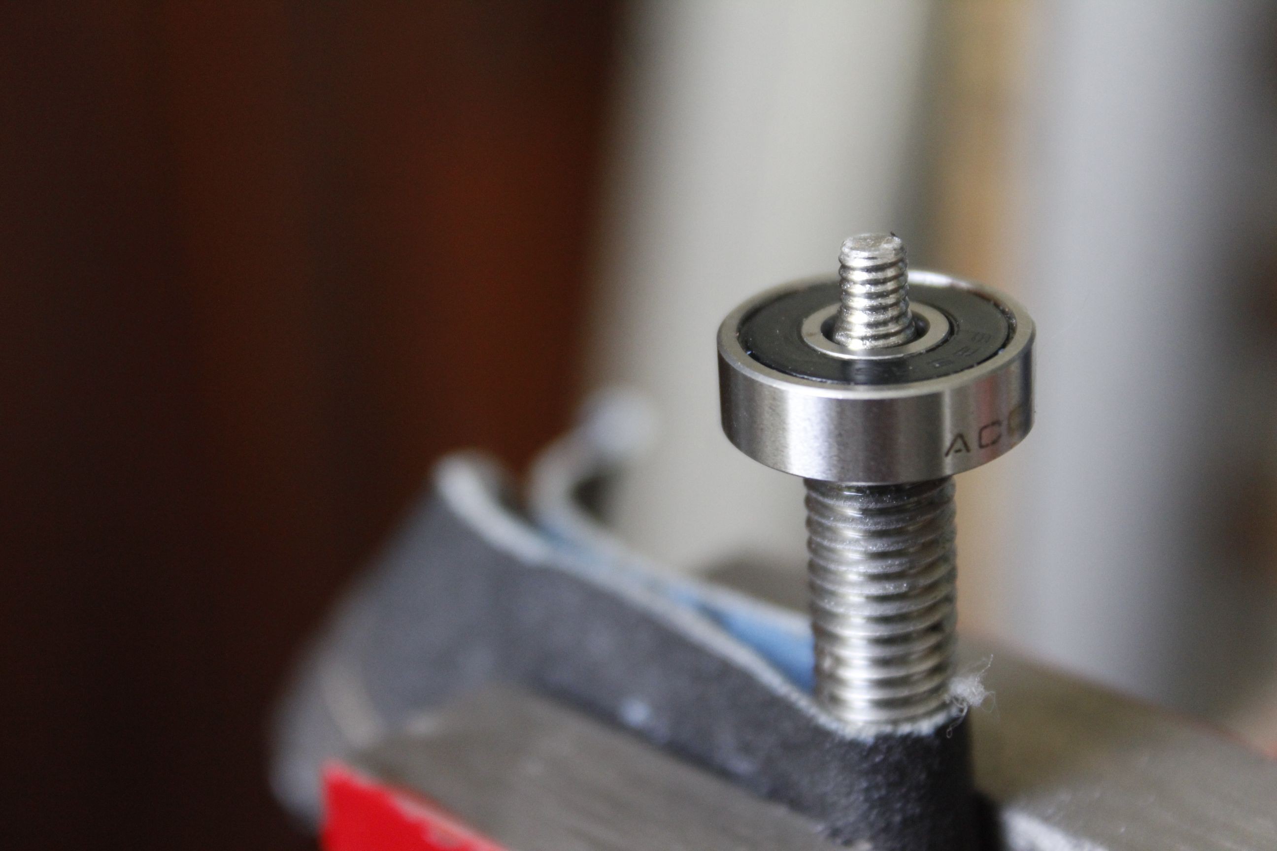
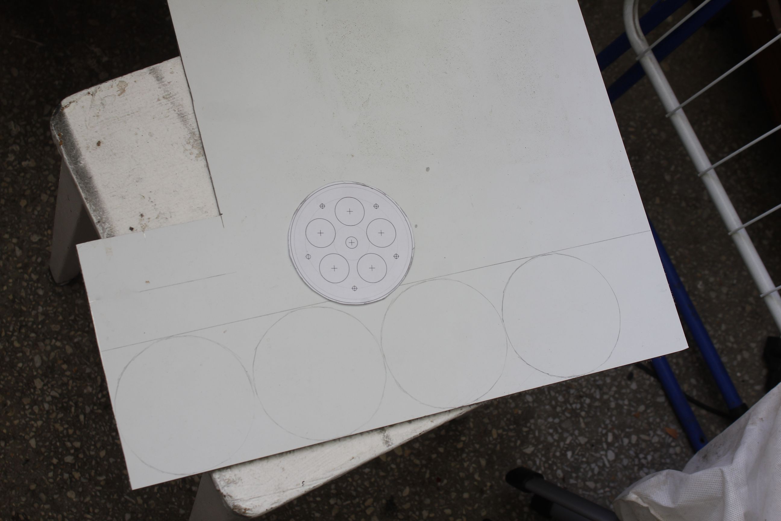
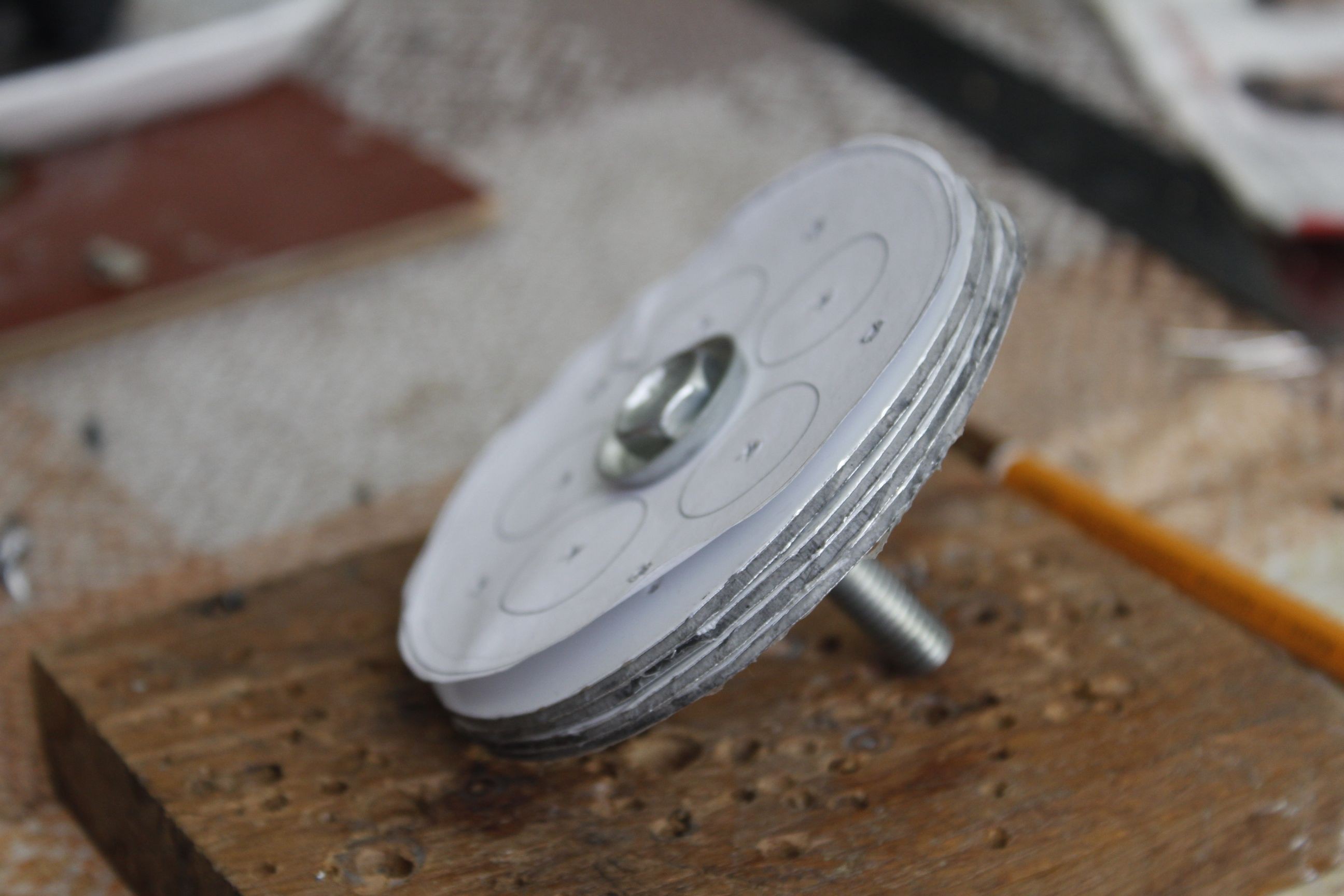
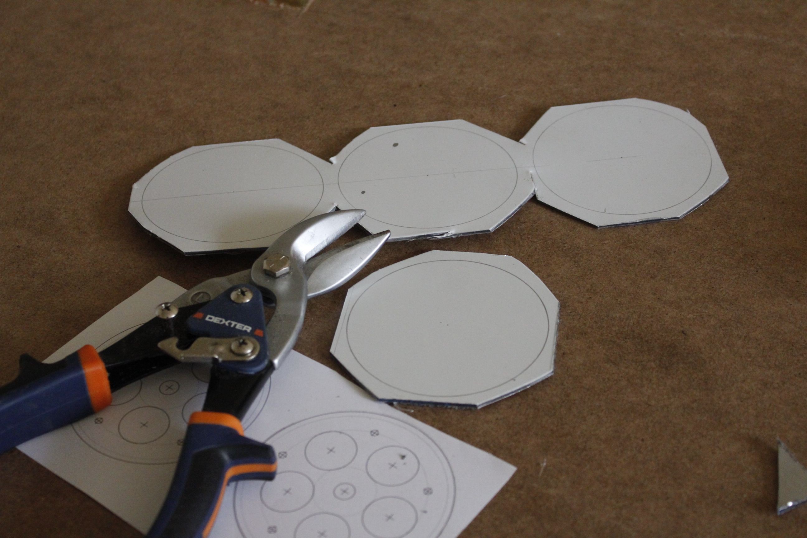
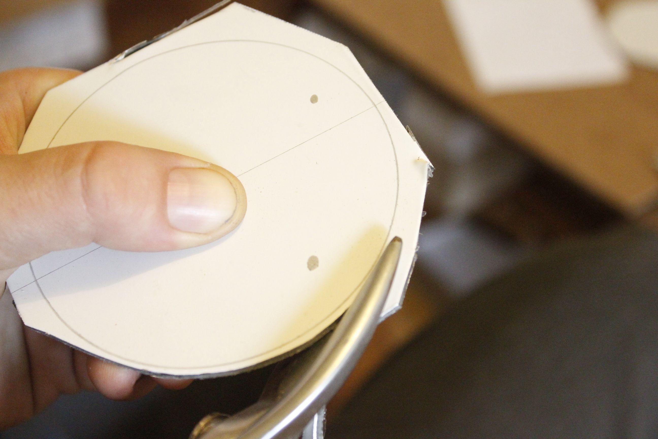
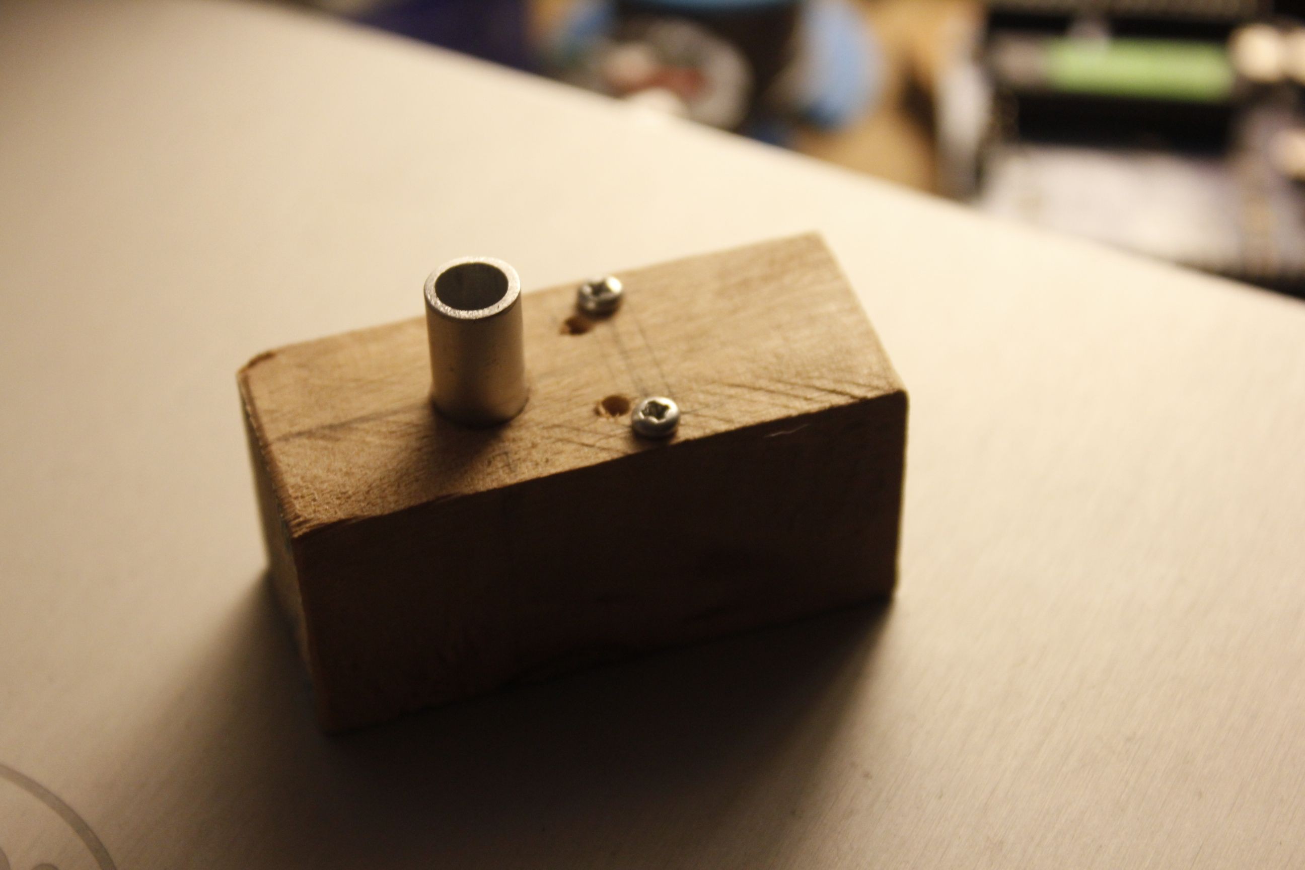
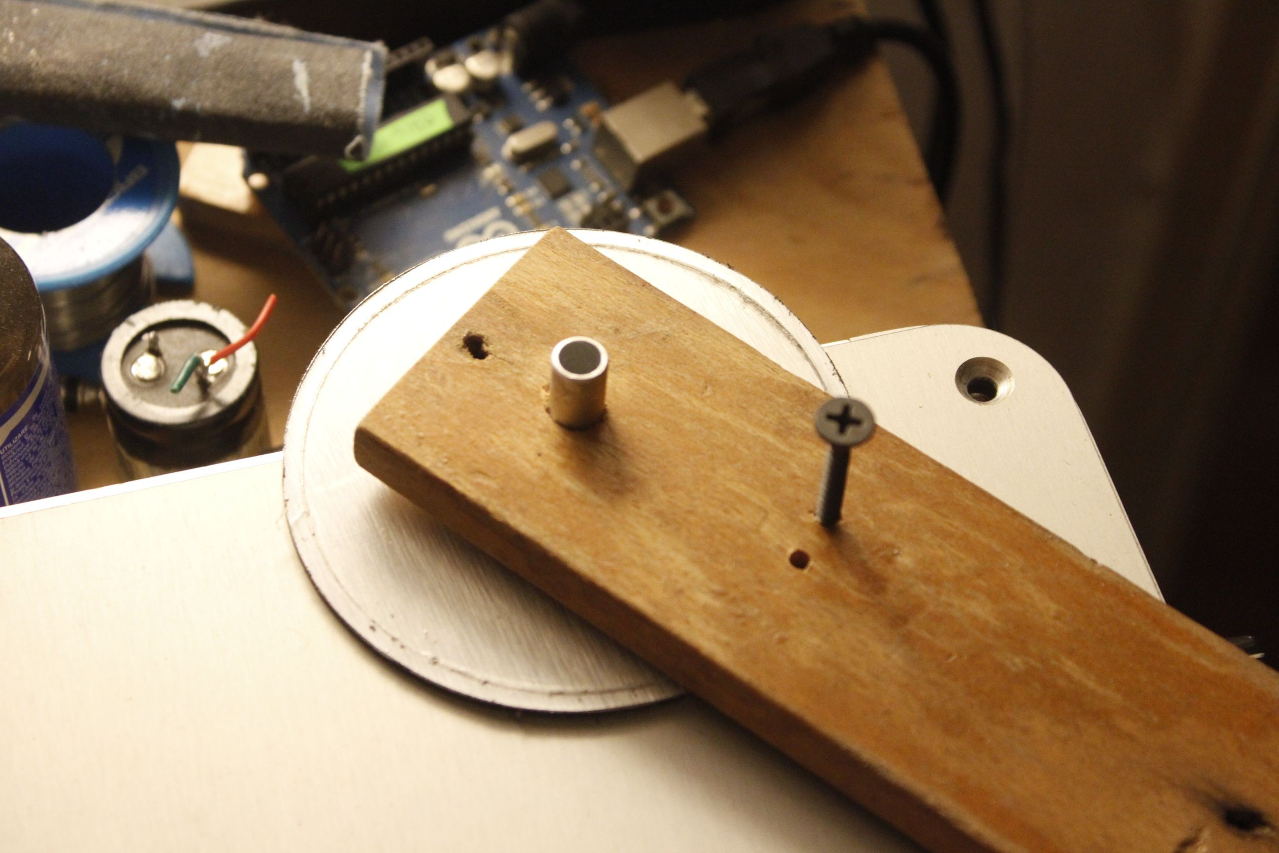
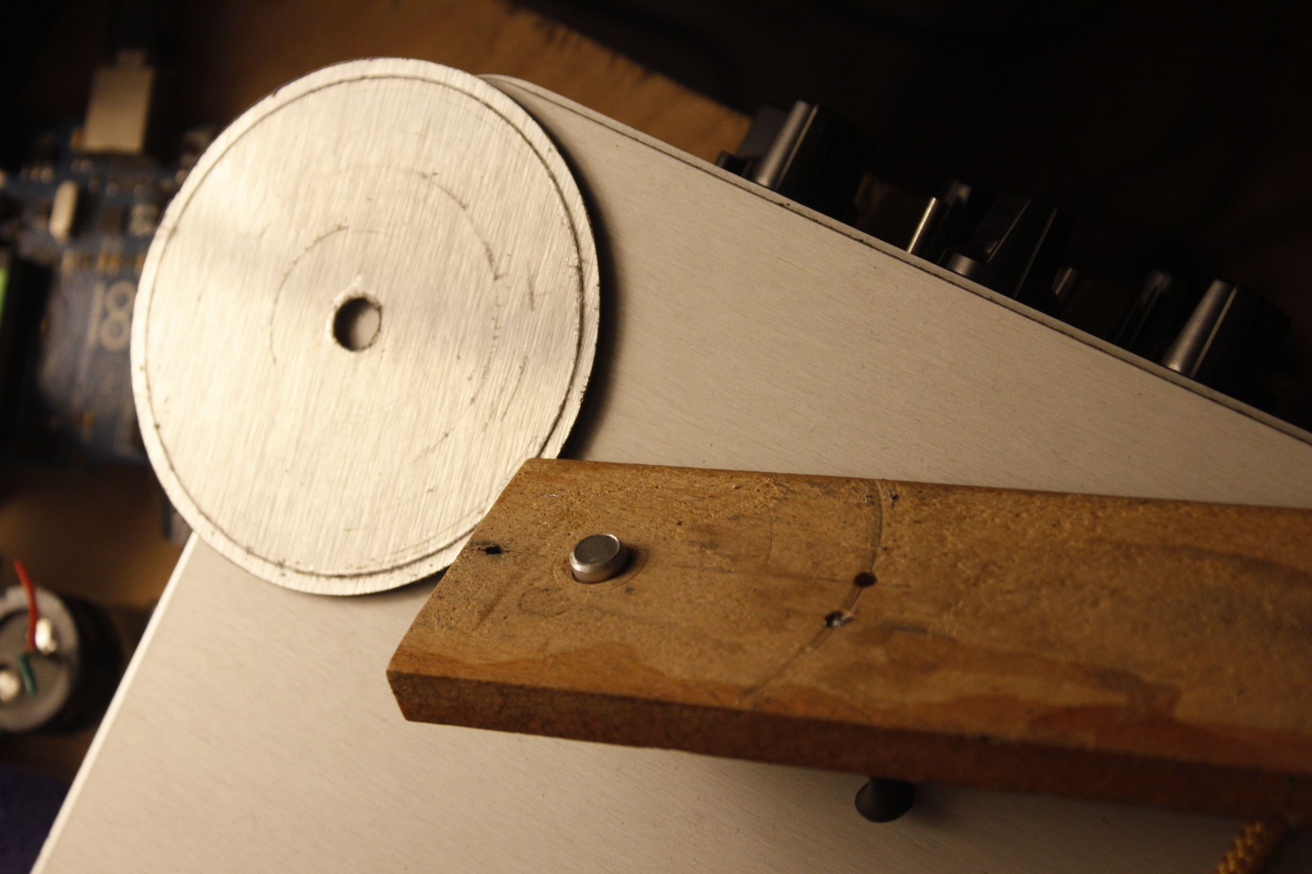
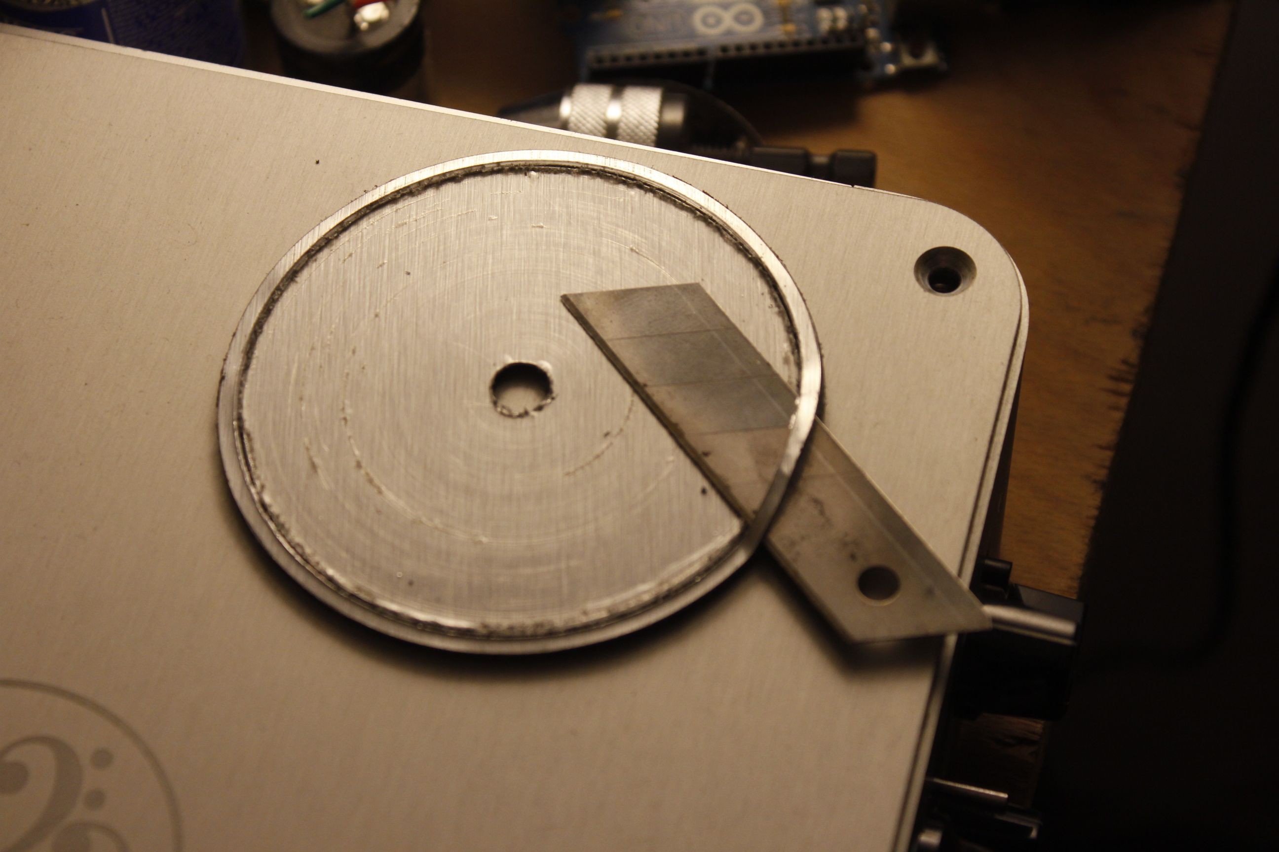
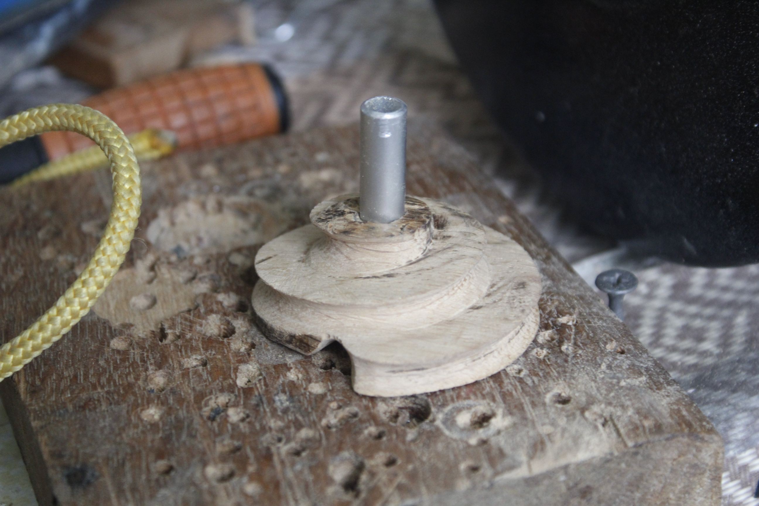
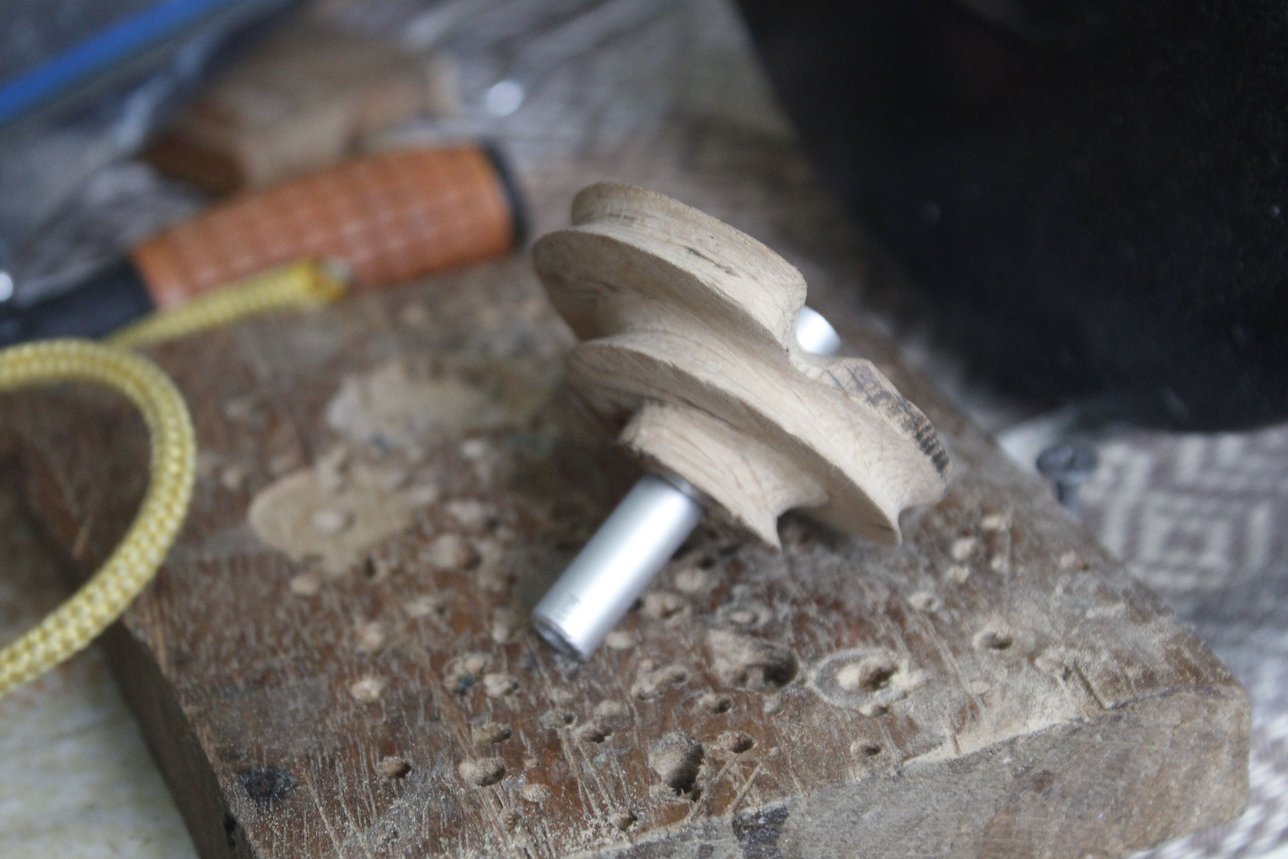
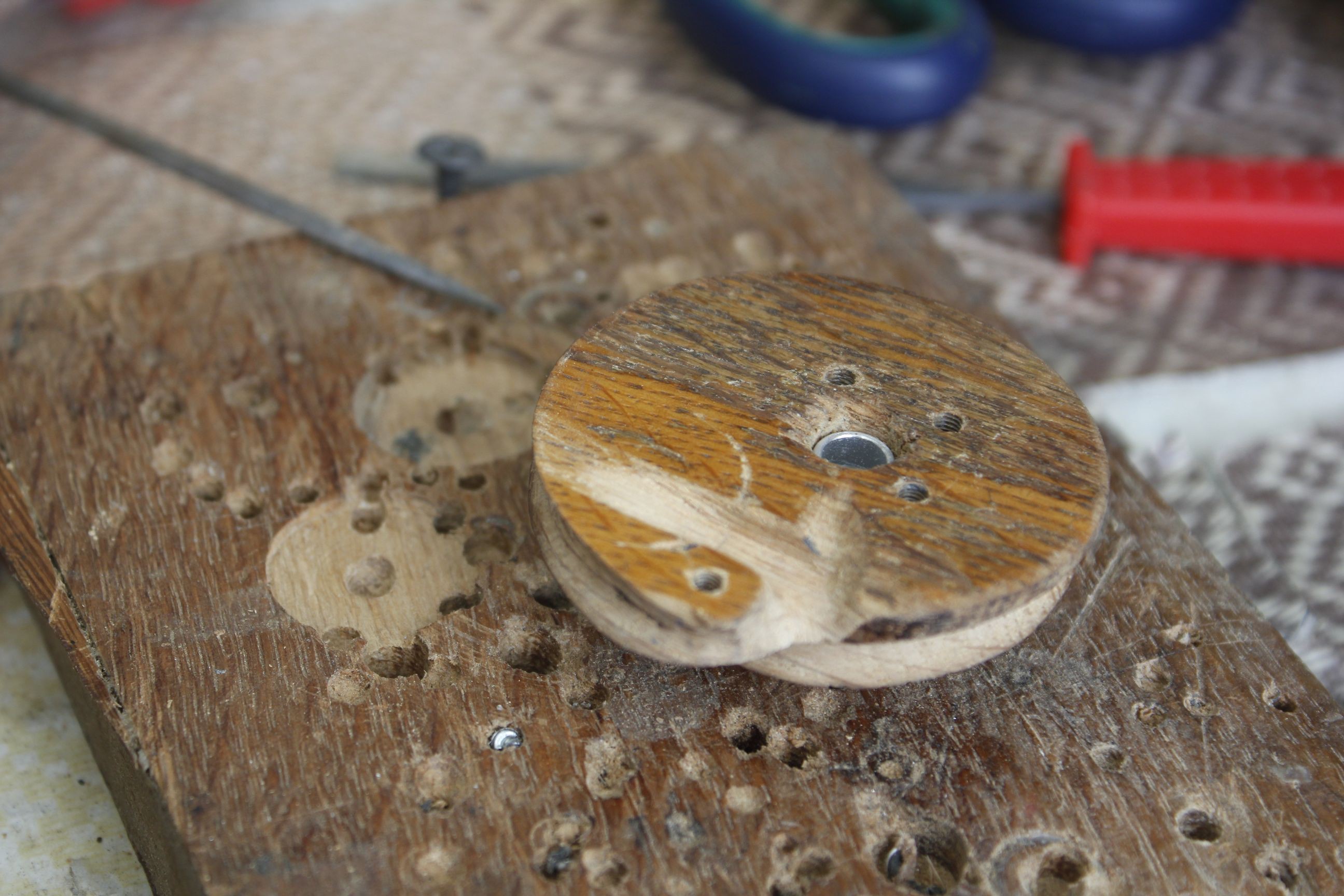
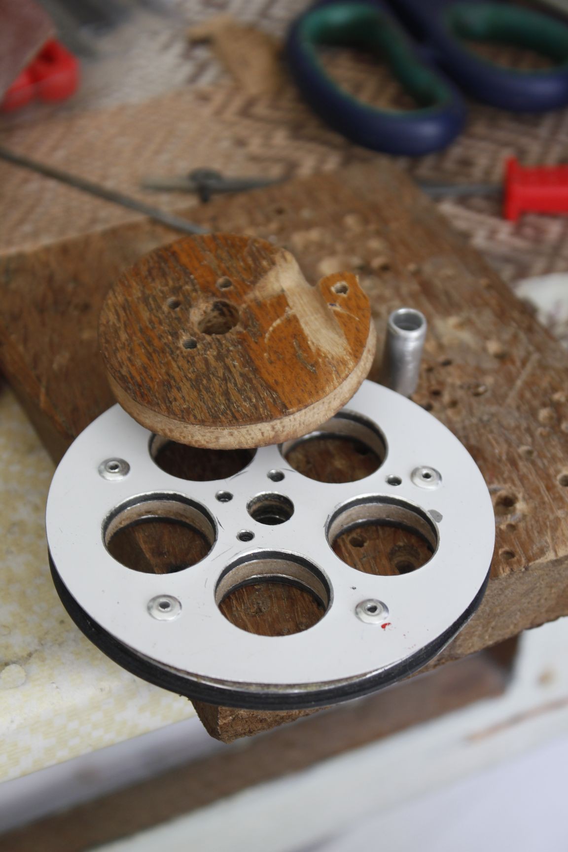
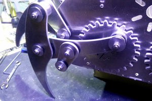
The solution was to use the geometry of a compound pulley/cam system, with three individual elements rigidly connected by a shaft: Two bowstring cams and a central driving cable cam, with its track built as a spiral, thus providing the necessary mechanical advantage in a more compact configuration. The string also winds twice around its tracks, thus halving their required diameter. This dimension also sets the maximum cam ratio, since the corresponding cable cam minimum diameter can be no less than that of the connecting shaft (8 mm). So any further reduction would probably be counterproductive, leaving us with 83 mm cams for a ~500 mm power stroke, which can reasonably be integrated into an ergonomic design. Having the string cams coupled to a single driving cam (and thus to each other) also eliminates the issue of cam synchronization, provided they are built to the same precise diameter.
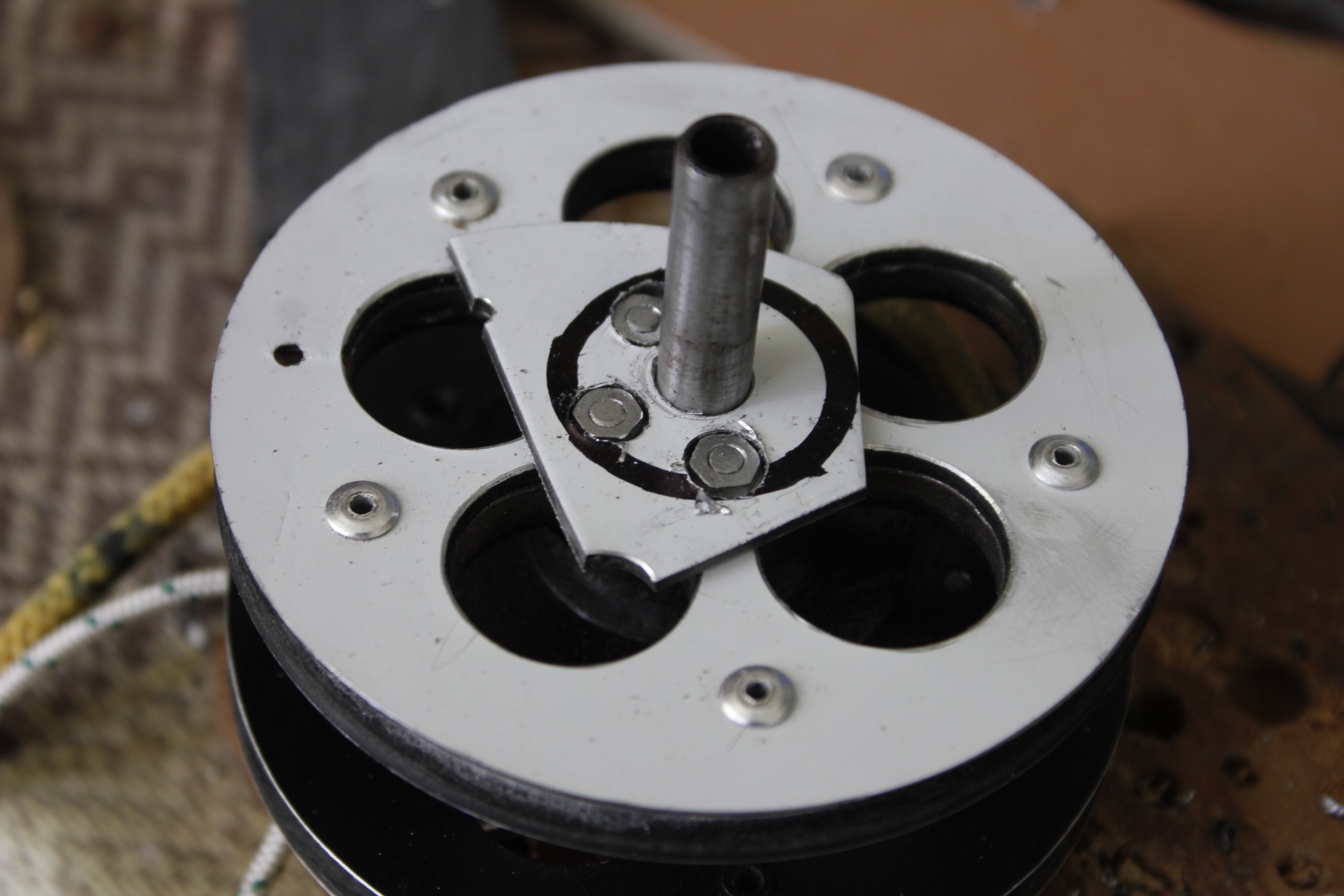
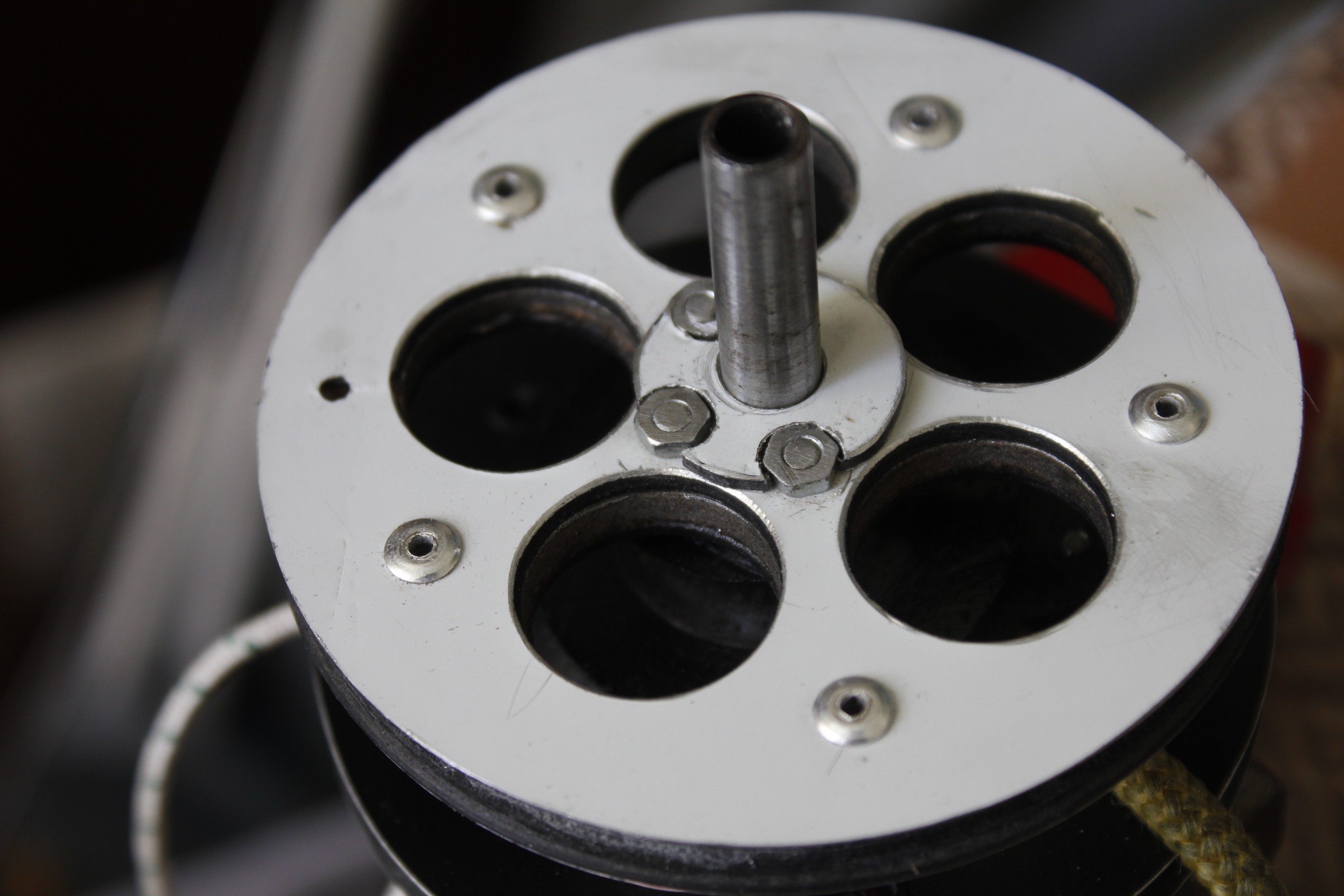
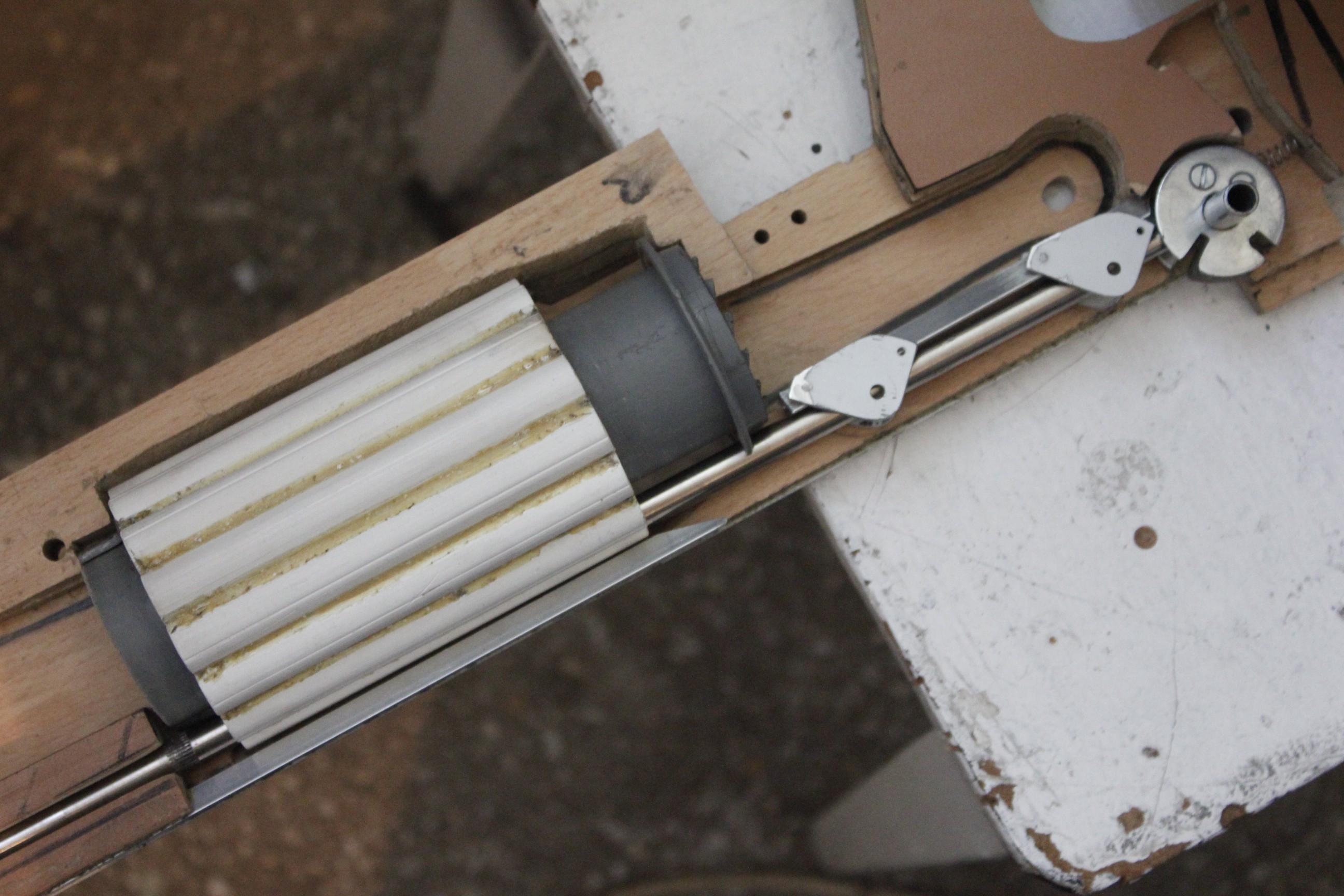
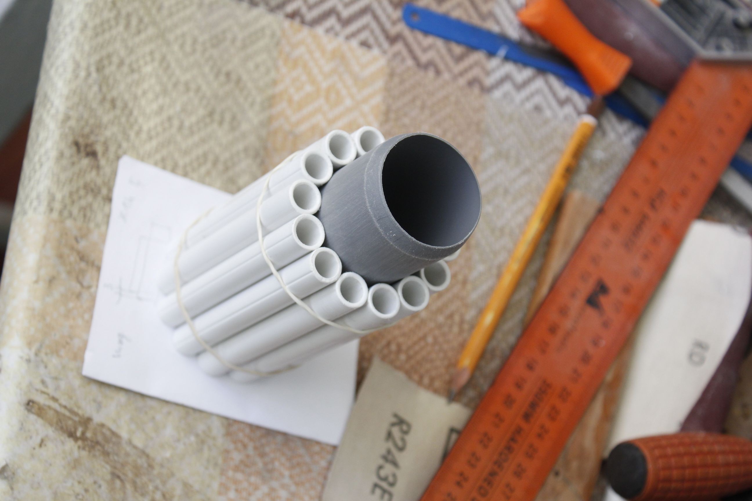
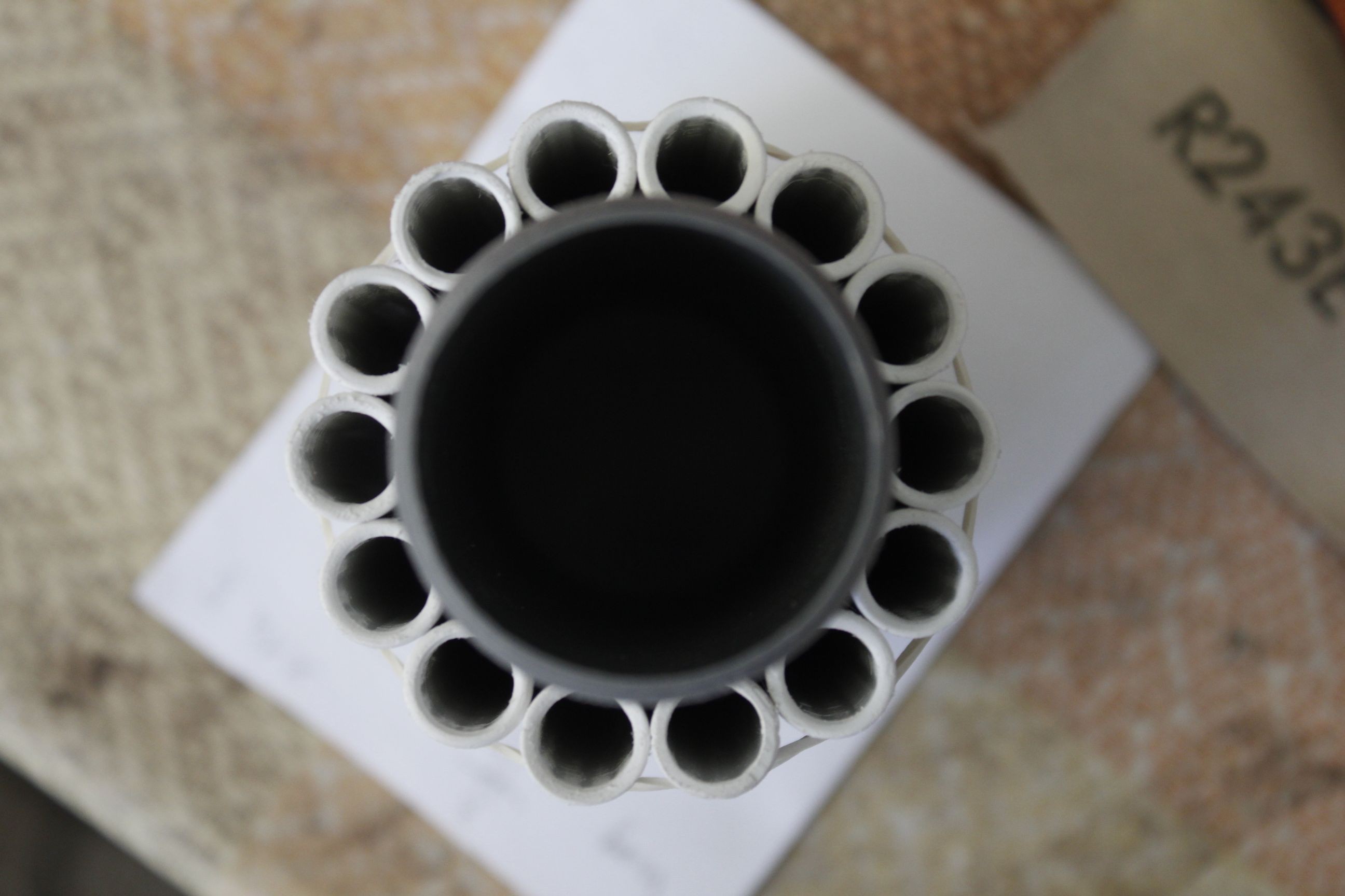
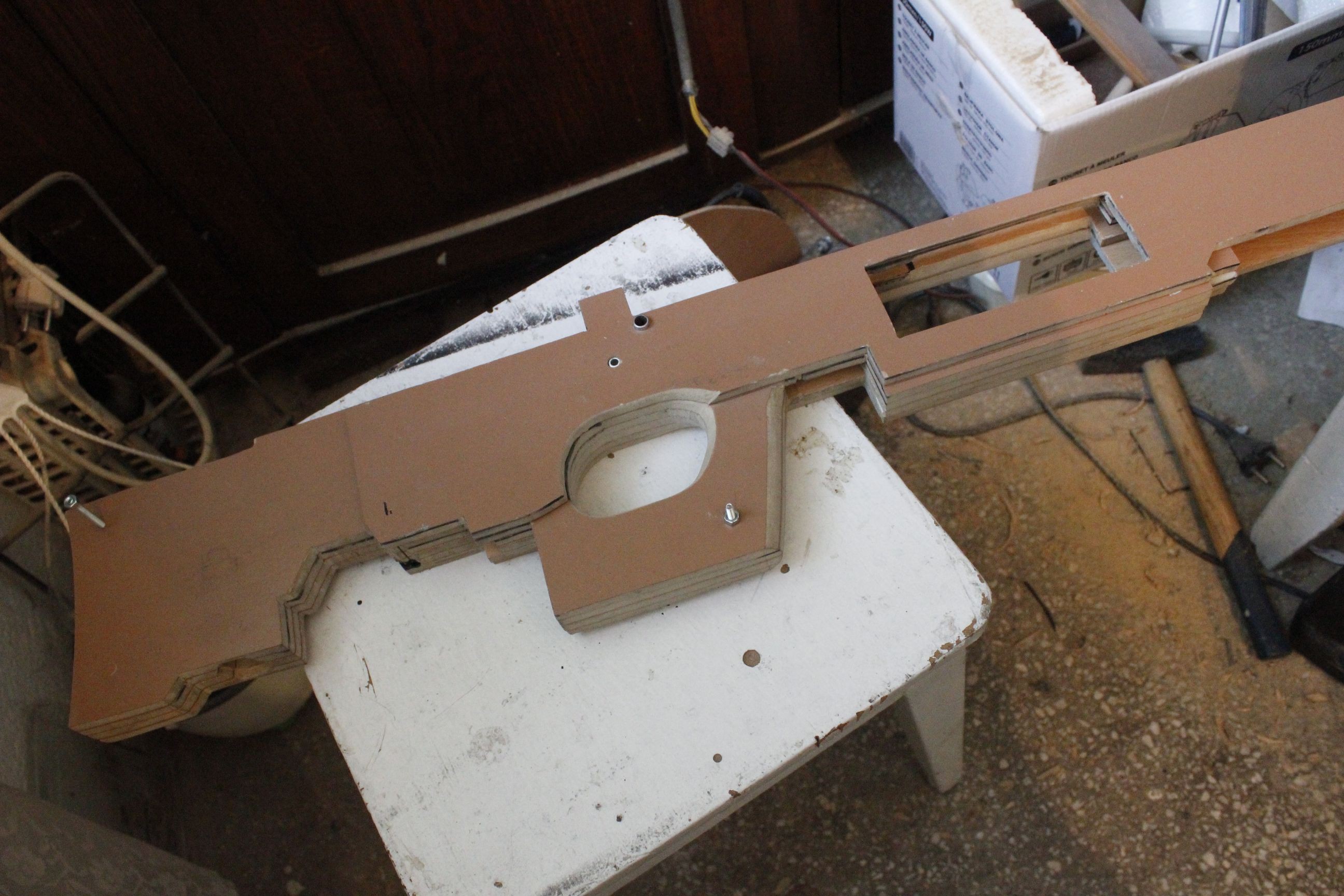
Locking in these choices allows more design elements to come together: the elastic bands shall be situated centrally, almost parallel to the bowstring. A drum-style magazine fits around them, forward to the end of the bowstring/string locking mechanism in order to clear for a loading ramp. This ramp sets the projectile in position once extracted from the magazine.
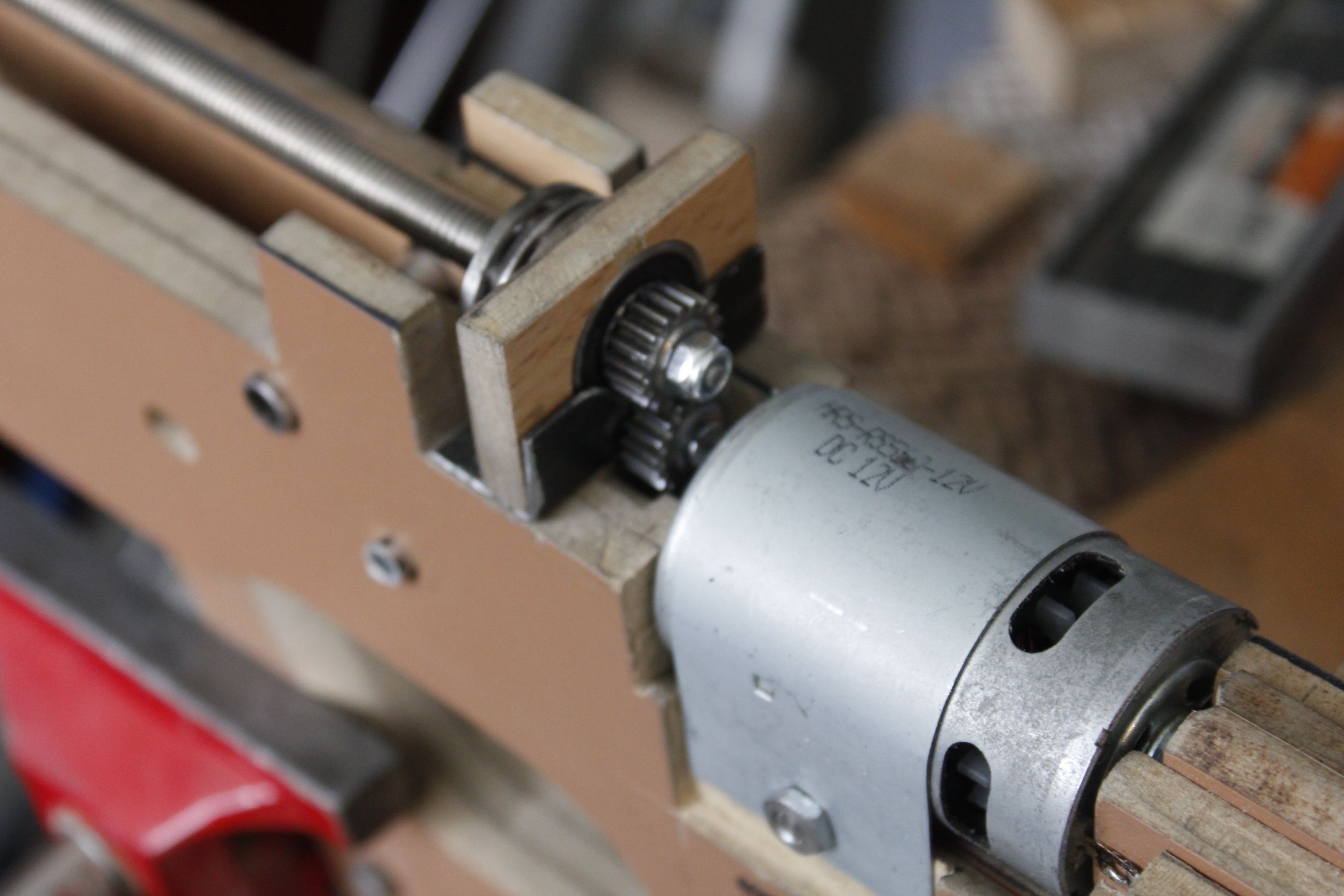
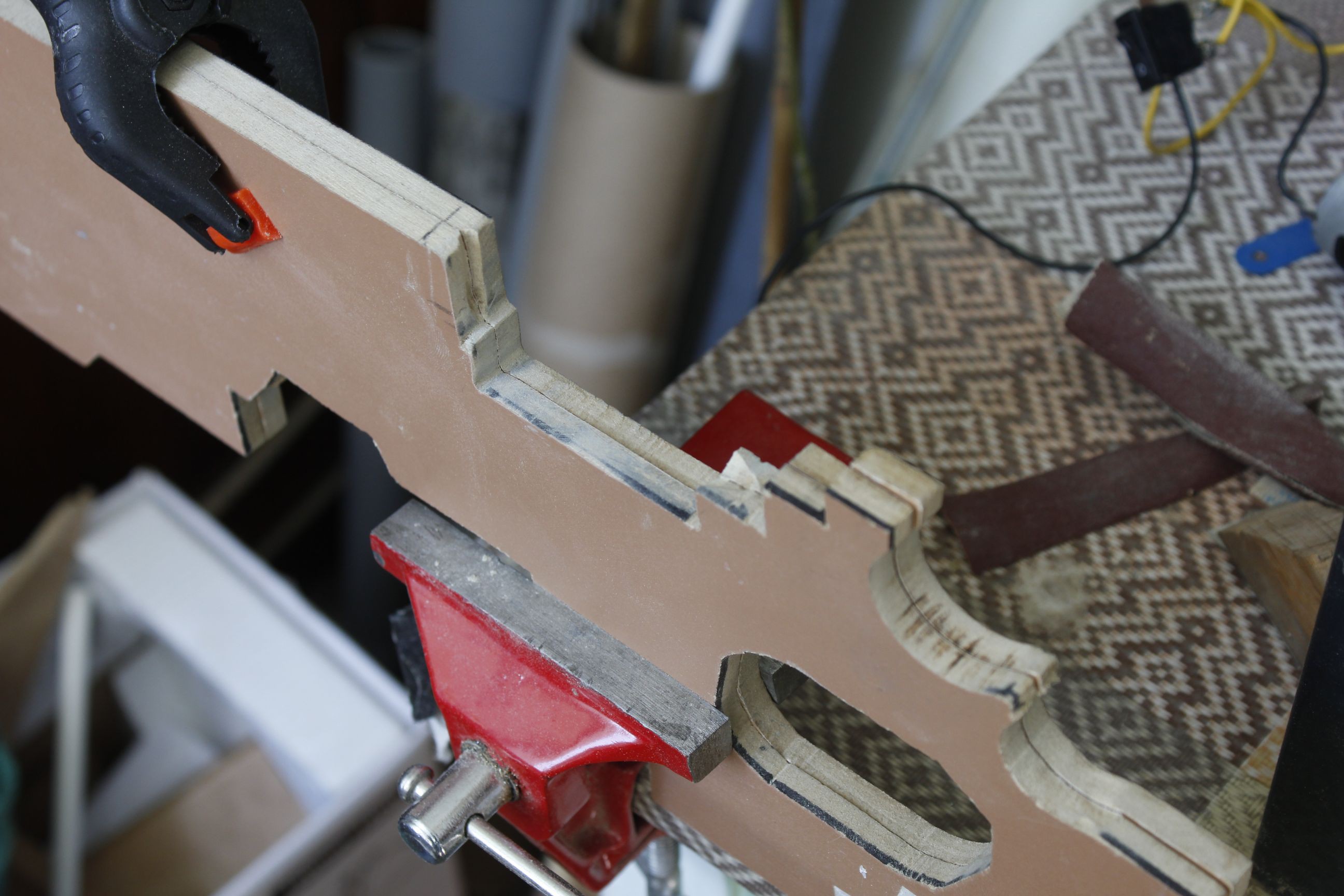
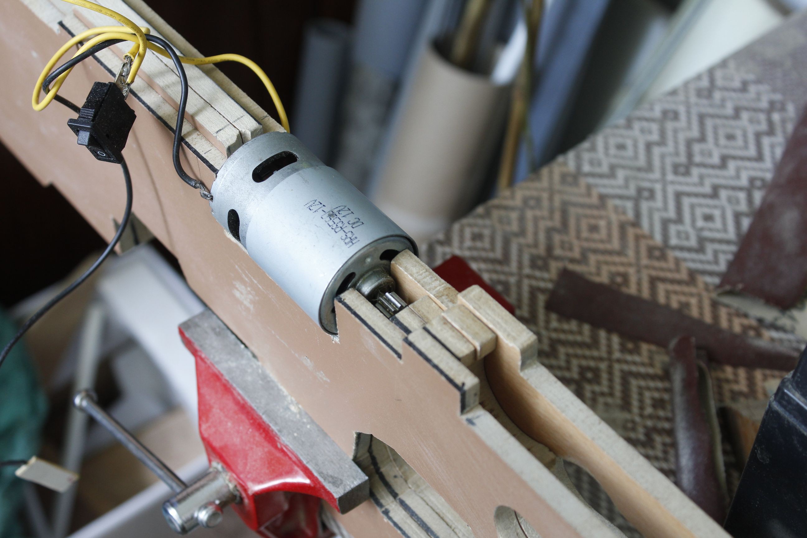
The next design focus was on the cocking system. One option was to engage the cam shaft directly, with a motor and worm gear reduction, such as a wind shield wiper motor assembly. This would have required a separate system to move the bowstring back in place and a way to decouple the reloading mechanism from the shaft for firing. In addition, it would not take advantage of the cams' levering action. Also it would have meant purchasing the assembly while the hand drill motors I already had would go unused, in lack of a suitable reduction. Another idea involved a bicycle chain that can engage the string and the shaft optionally, and could provide continuous cocking motion. The bike chain was impulsively bought and much time was sunk in sourcing a worm gear reduction and appropriate sprockets to no avail, and this solution had to be scrapped.
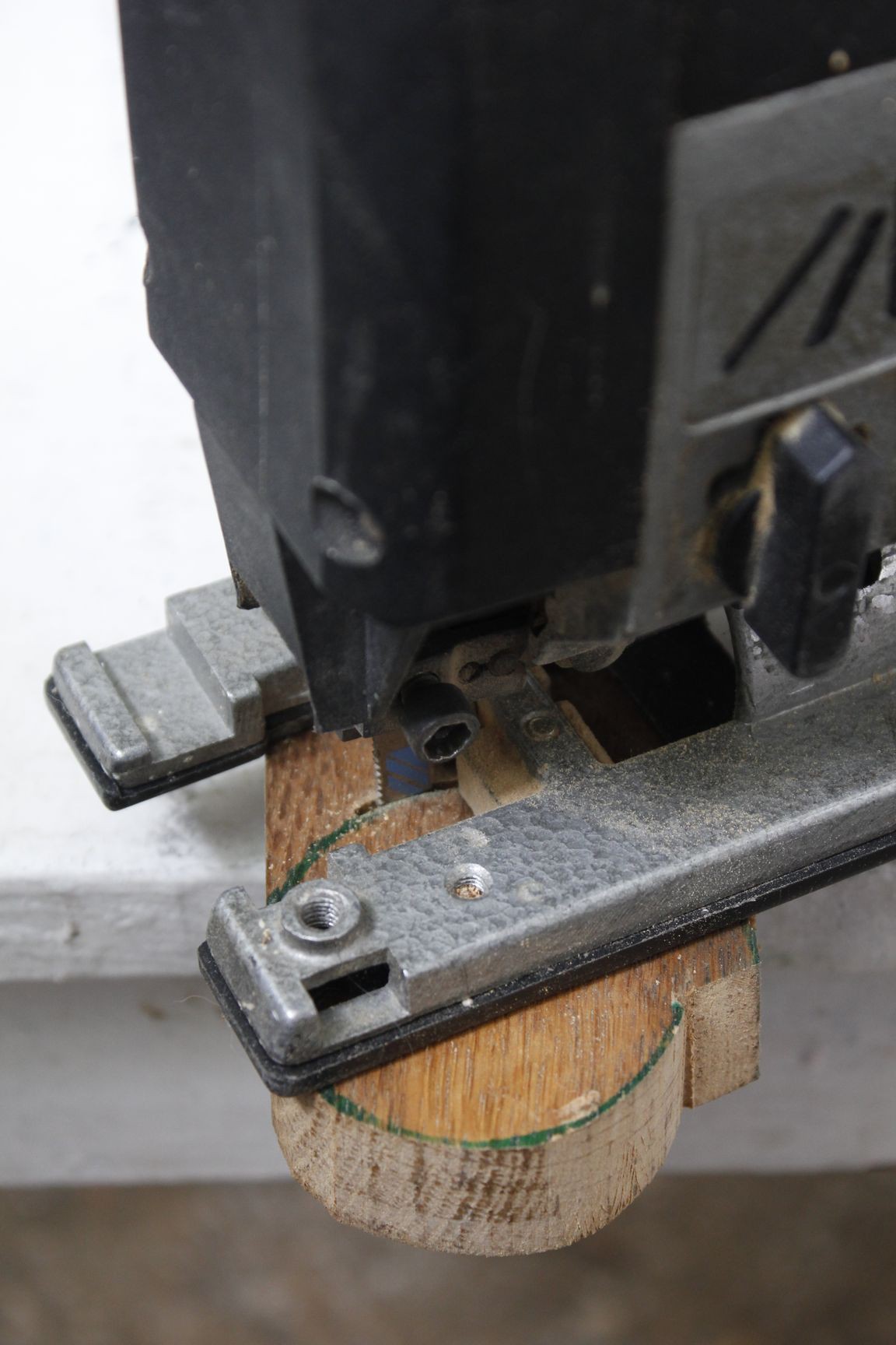
The ceaseless utility of the inclined plane...
Read more »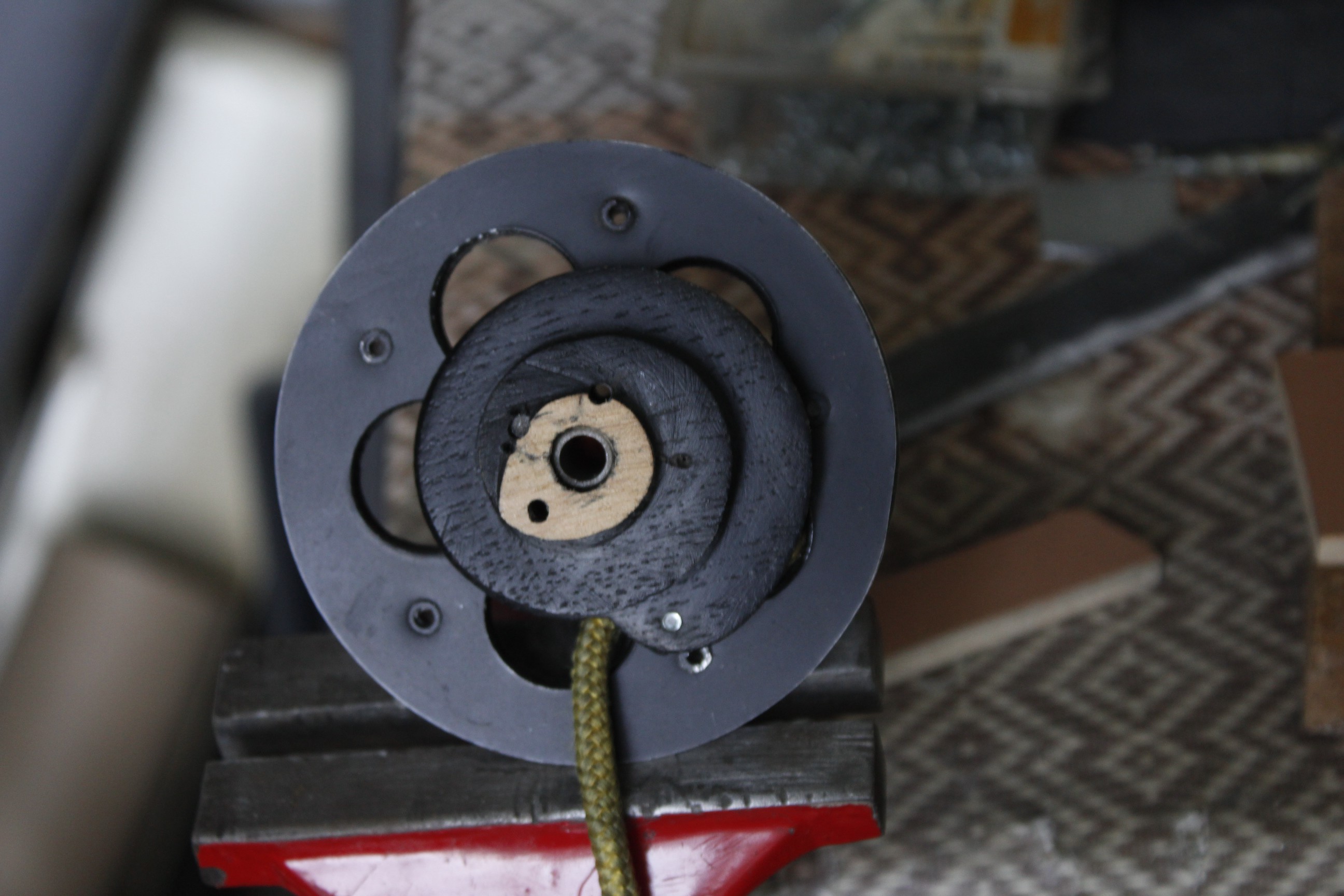


 Pinomelean
 Andrew Mayhall
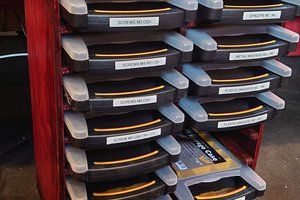
 Zoé
Zoé
Interesting, I wonder if this would also be useful for dealing with tokoloshe? They've been mostly driven out now, but every now and then there's a sighting...