 Ethan Durrant
View the Code and Documentation on Github here:
https://github.com/emdarcher/Vintage_Beauty
Features:
- Can display the US ASCII character set, as well as Japanese Katakana and Hiragana using a custom 5x7 pixel font stored in the program ROM. (I love Japanese, so had to get it in there!)
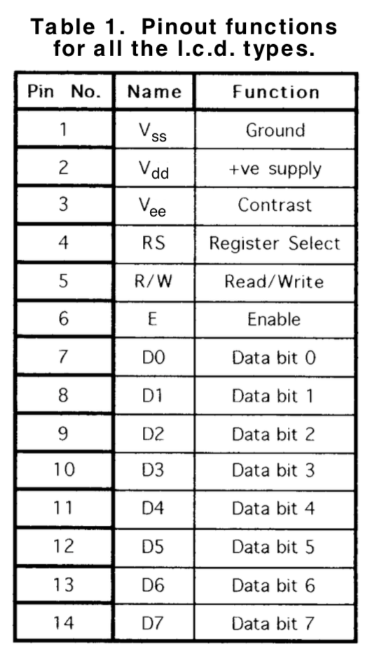
- The ROM character sets are based off the those in the HD66702 LCD driver chip found in many Character LCDs.
- Communicates with the displays through an optimized Bit-Banged SPI-like protocol utilizing the the 8051's bit-addressable memory for speed. Based on code found here but modified for SDCC.
- Written in C and compiled using the Open Source Small Device C Compiler (sdcc)
Work in Progress:
- Full HD44780/HD66702 LCD Driver emulation via GPIO ports.
- Serial UART control.
References and Datasheets:
Vintage Beauty Demo:
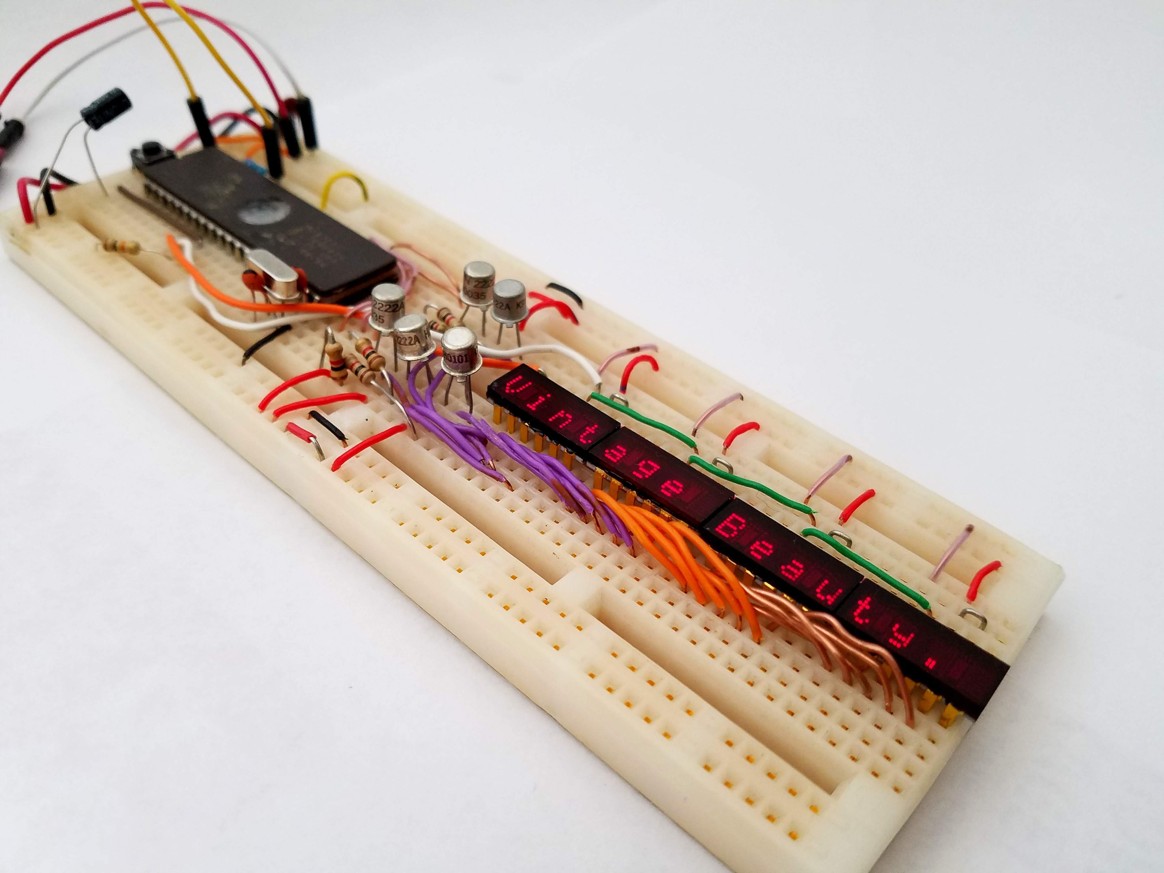
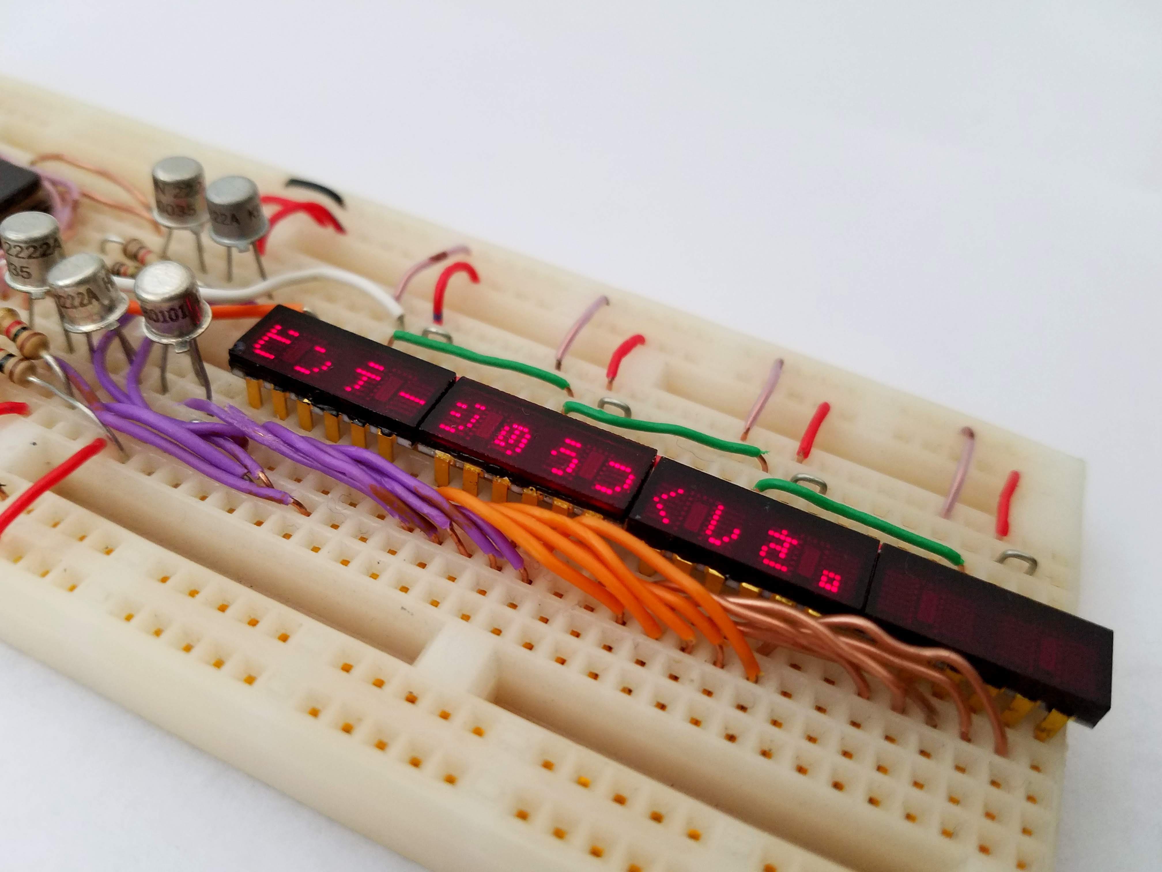
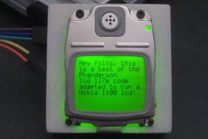
The demo displays the messages "Vintage Beauty." or 「ビンテージのうつくしさ。」in Japanese on the displays. The message is selected based on the value of GPIO P0.3 at reset, being HIGH for English, or LOW for Japanese. Make sure to use an external pull-up resistor of around 10k Ohms on that pin as it lacks an internal pull-up.
This is meant to show the basic functionality of the code to display a programmed internal message.
Pictures:
Basic Demo:
Japanese Demo:
 Top View for the Hardware Setup:
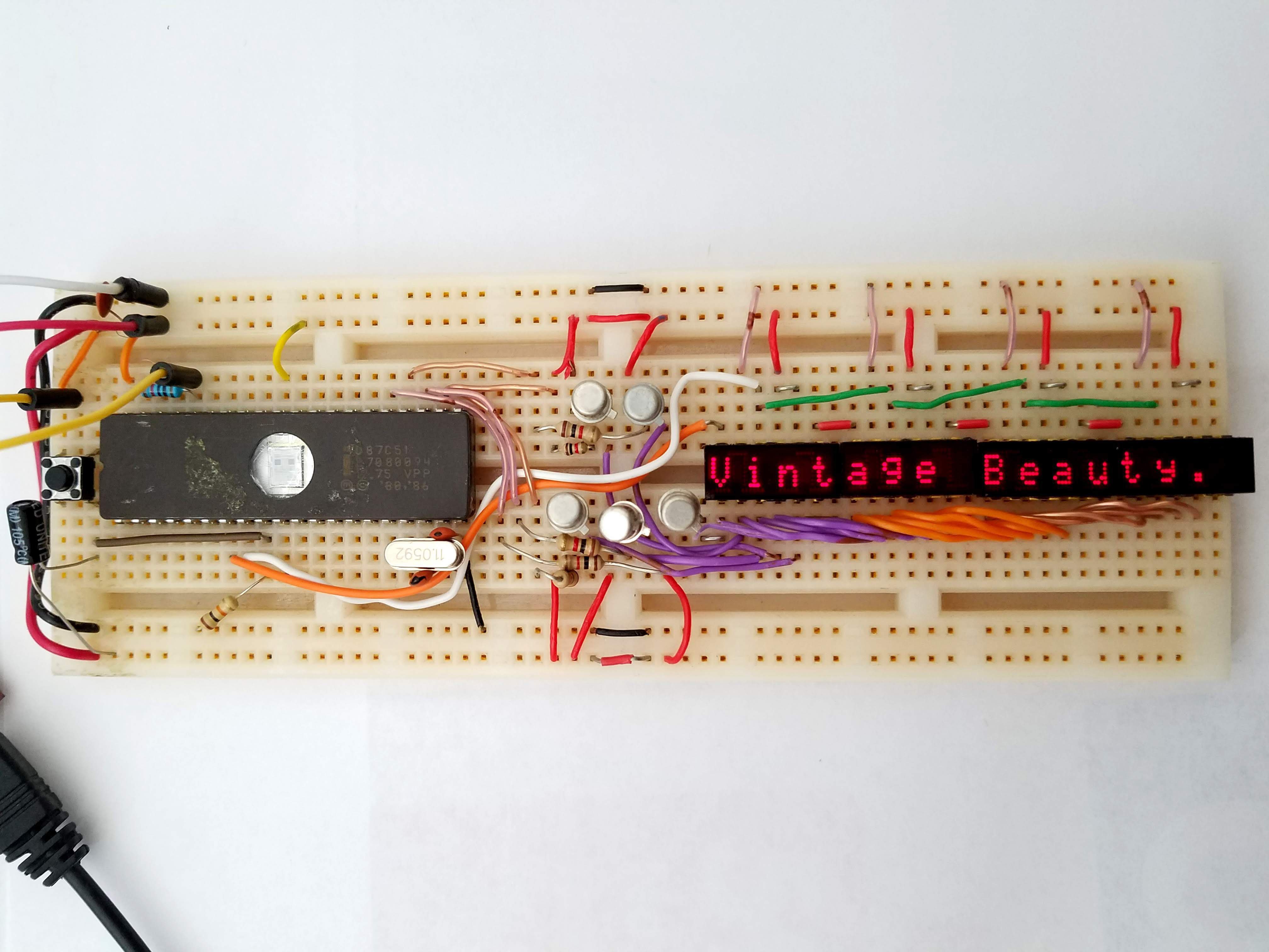
Hardware setup:
- Port 2 bits P2.0-P2.4 are used for driving the 5 display columns via NPN transistors.
- P1.6 is used as SPI Serial Data Out to the displays, entering at the left-most display.
- P1.7 is used for SPI Clock output to the displays, shared Clock signal by all displays.
- P0.3 is the message selection pin which is read on Reset. HIGH == English, LOW == Japanese. Pulled-up by an external 10k Ohm resistor (Port 0 has no internal pull-up resistors).
- The 8051's RESET pin is pulled low by an external 10k Ohm resistor and also tied to the negative terminal of a 10uF Capacitor, with it's positive terminal at +5V to generate a Power-On Reset. A push-button switch that connects RESET to +5V can optionally be added as an external Reset Switch.
- A 0.1uF decoupling capacitor is recommended between +5V and GND near to the 8051 Microcontroller.
Programming Information:
For the Code, I used the Open Source Small Device C Compiler (sdcc) for compilation. I used a Mac this time, but it should work on Linux as well. Don't know much for Windows, but it's probably similar. On Mac this can be installed using HomeBrew with brew install sdcc. On Linux, you can use your package manager, or just install from source.
To select a different ROM Character set, and configure other settings related to the ROM, you can change the values defined in the ascii5x7.h file. ROM_CODE can be set to ROM_CODE_A00, ROM_CODE_A01, or ROM_CODE_A02 which relate the the ROMs of the common HD66702 LCD Driver.
Compilation:
First compile the ascii5x7.c file with the character ROM data:
sdcc -c ascii5x7.c
Then compile the main program along with the relation file to include the library:
sdcc main.c ascii5x7.rel
After compilation you need to convert the Intel Hex *.ihx output to a regular hex file *.hex.
You can do this using the packihx tool that comes with SDCC.
To convert the main.ihx file and write the output to the new file main.hex:
packihx main.ihx > main.hex
Flashing the Microcontroller:
To Flash the Microcontroller I used the TL866CS MiniPro Programmer, which seems to be able to flash almost any MCU or EPROM I've found. Any TL866 version should work.
I use this programmer because it has a great Open Source tool available for it called minipro which you can find here:
https://gitlab.com/DavidGriffith/minipro/...


 ogdento
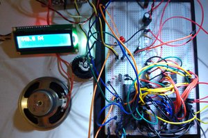
 Ken Yap
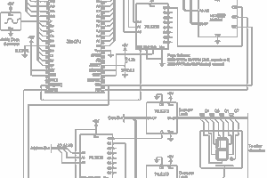
 6502Nerd
Love these old displays, very nice. I must be missing something in the pictures. How are you driving the columns with NPN transistors? I would expect PNP.