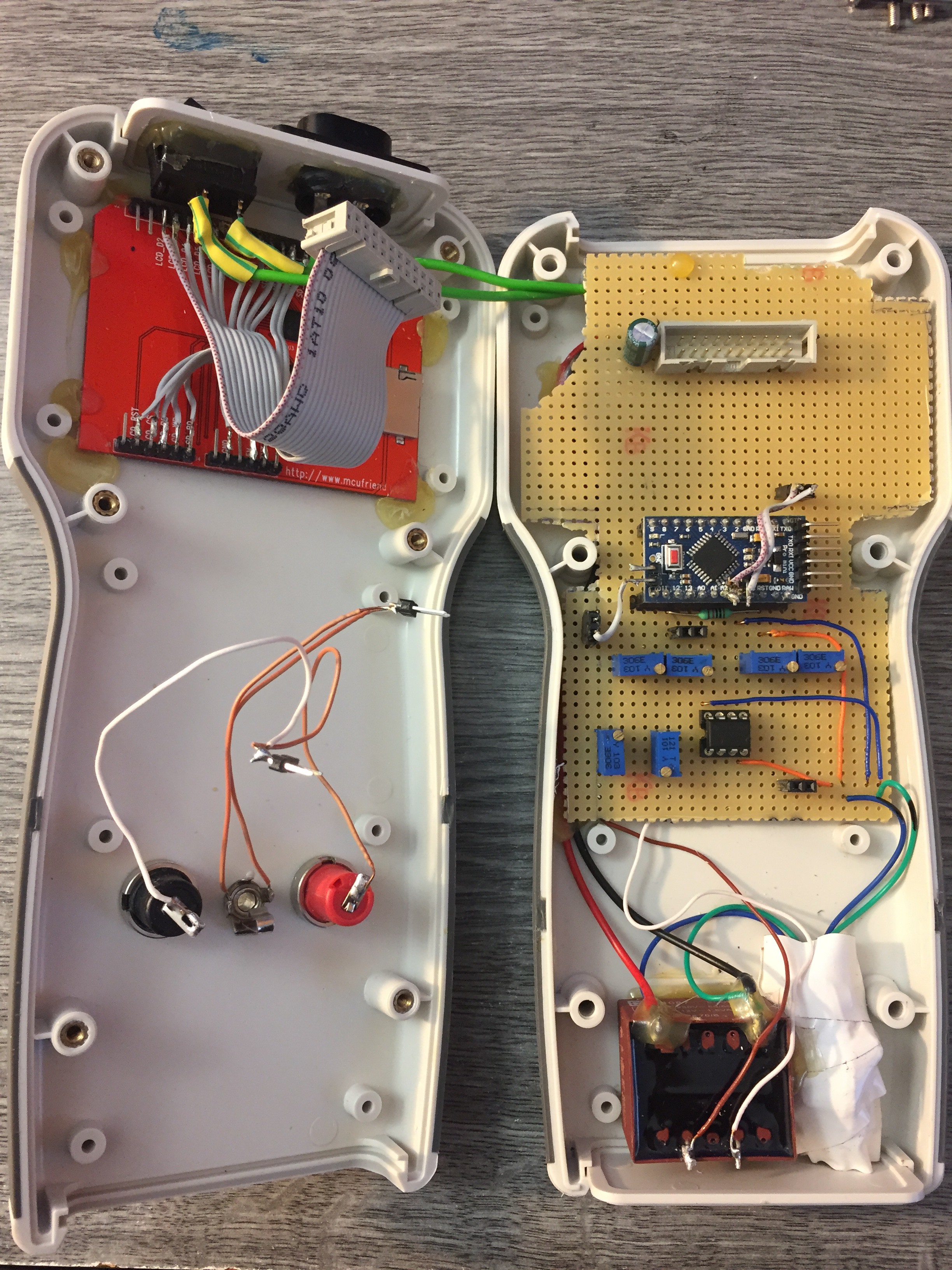
The hardware:
It has tree main part, which are:
- Display (2.4" TFT Touch display)
- Arduino pro mini (5V 16Mhz version)
- Analog stage of the curve tracer
The display has 320x240 pixel resolution, which is perfect for this application. I only use 240x240 pixels for the curves and the other part of the screen is used to show some basic parameter, which is minimum and maximum measured voltage. These two voltage point can show you the break down points on the Zener diode for example.
When I was developing the sketch I was optimistic to use the Arduino pro mini, but end of the project I had to realise it can not handle very well the display functions and at the same time the measure functions. I ran out very quickly of the 2K RAM, so I had to do some optimalisation. In the "final" code I am using half of the program memory and almost 90% of the RAM. On the Pro Mini I had to use almost all digital and analog pin, to make it working.
For power the microcontroller and the display I used a small DC-DC converter, which I not recommend to do, because I figured out it makes a lot of noise. This noise has a very bad effect on the current measurment, that why I do not have a perfectli straight line on the display.
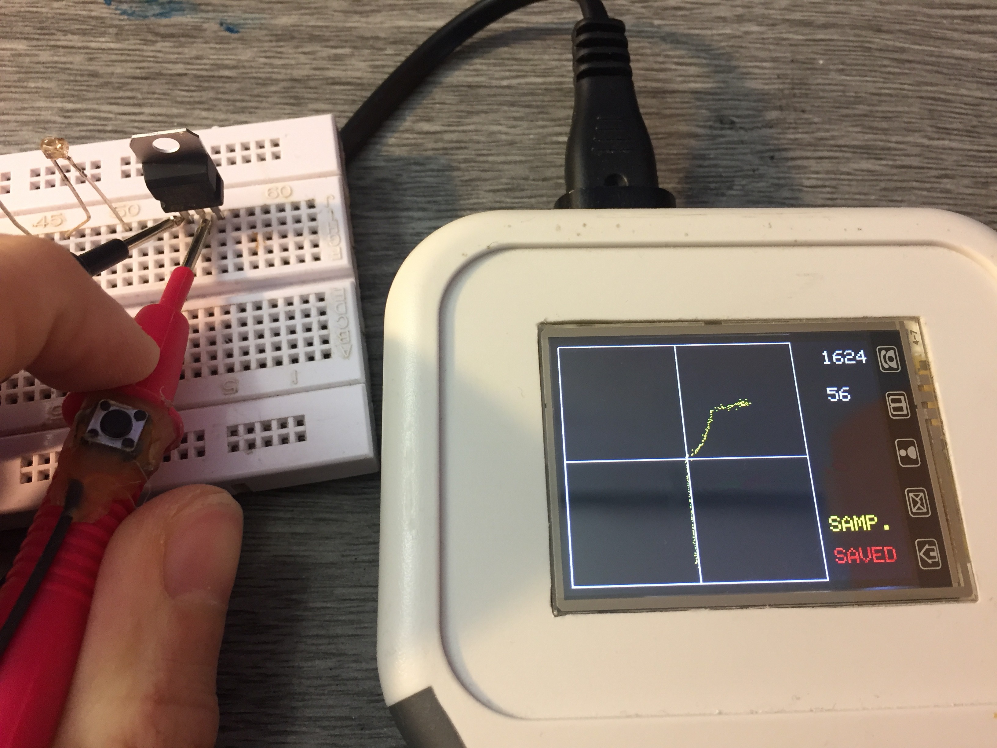 On the picture above you can see I hacked a button on the red probe. That button has a purpose, if you push it when you measure something, the tracer can store that curve into the memory. The stored curve showed on the display as a red curve, and same time you can measure a other component, which you want to compare it.
The software:
Part of the code was from my other project, which was a simple arduino oscilloscope I made. I never thought I can use it for anything usefull, because of the low speed, but for this project it was perfect. I modified to handle two channel, and it worked perfectly.
In this project I did not need any trigger function, because it does not matter where the drawing is starting. It just simple measure 240 point on each channel as fast as can do, and after those stored in two array, it start drawing the dots on the display.
After all this project was successful for me, I learned a lot.
A slow mo video how it works:
Upgrade plans:
In the future I would like to separate the display functions from the measure functions.
I am thinking about to make a function generator for drive the analog section, and then I can change the voltage, frequency and with some other component the resistance, with I can limit the current.
Discussions
Become a Hackaday.io Member
Create an account to leave a comment. Already have an account? Log In.