Close
0%
0%

Joy Boy

Jump into the action with this awesome joystick for your Game Boy®. Now you're playing with power. Stick power.

Similar projects worth following

There's a handful of cool peripherals for the Game Boy®. Like Pocket Sonar, the perfect companion on your next fishing trip, or PediSedate, designed to reduced stress when sedating your child.

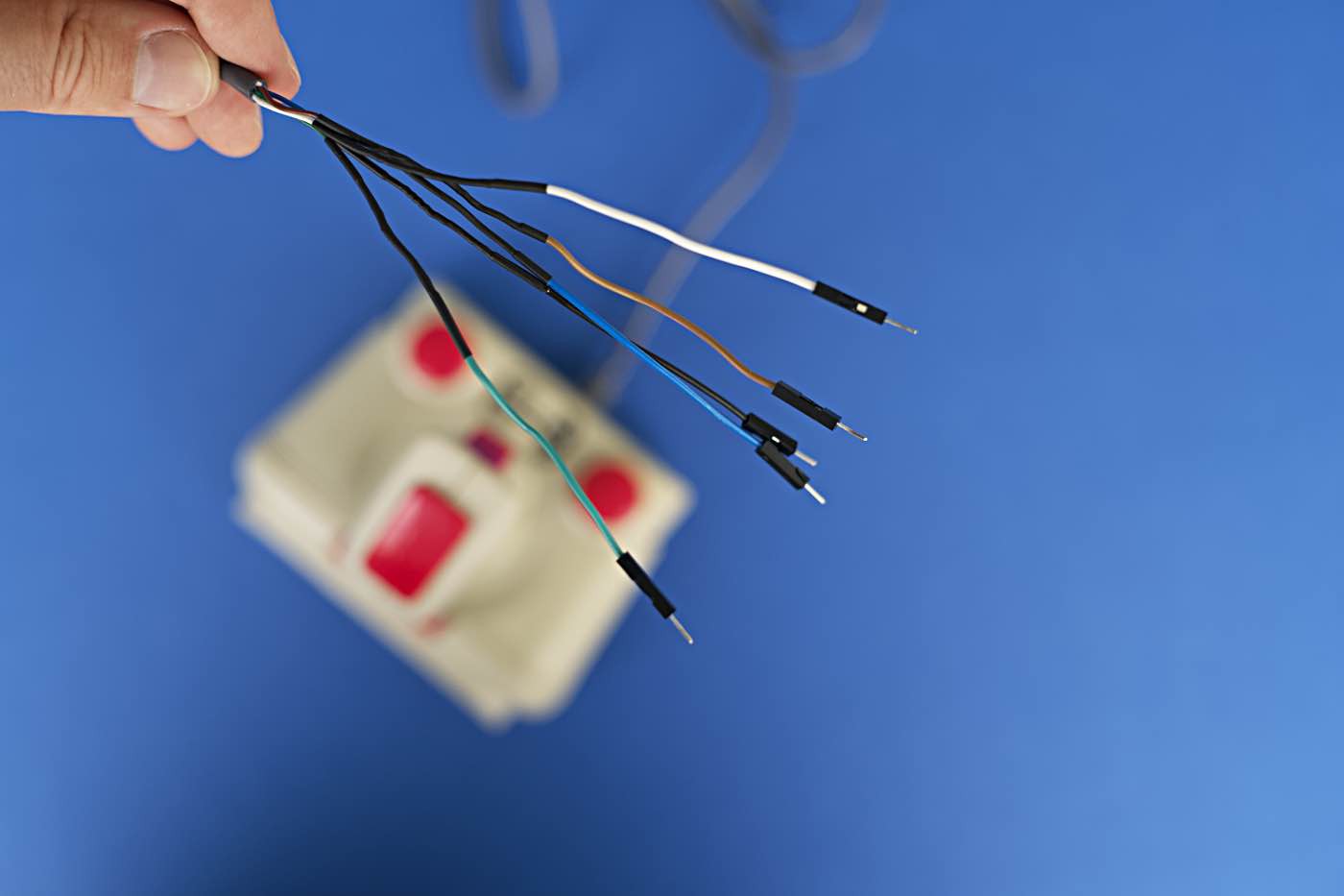
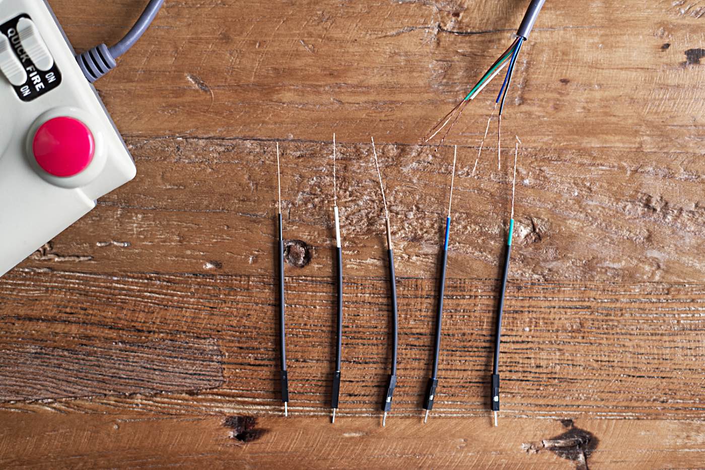
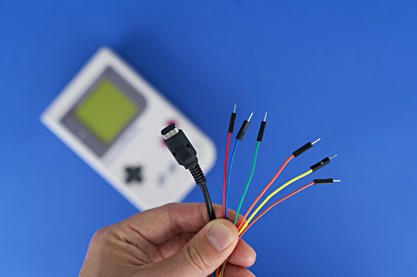
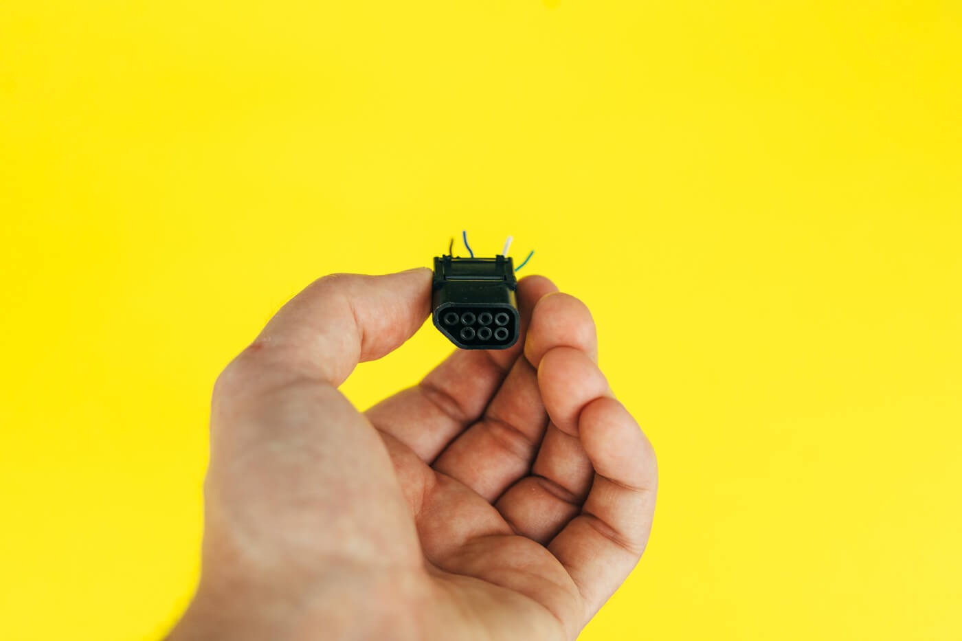
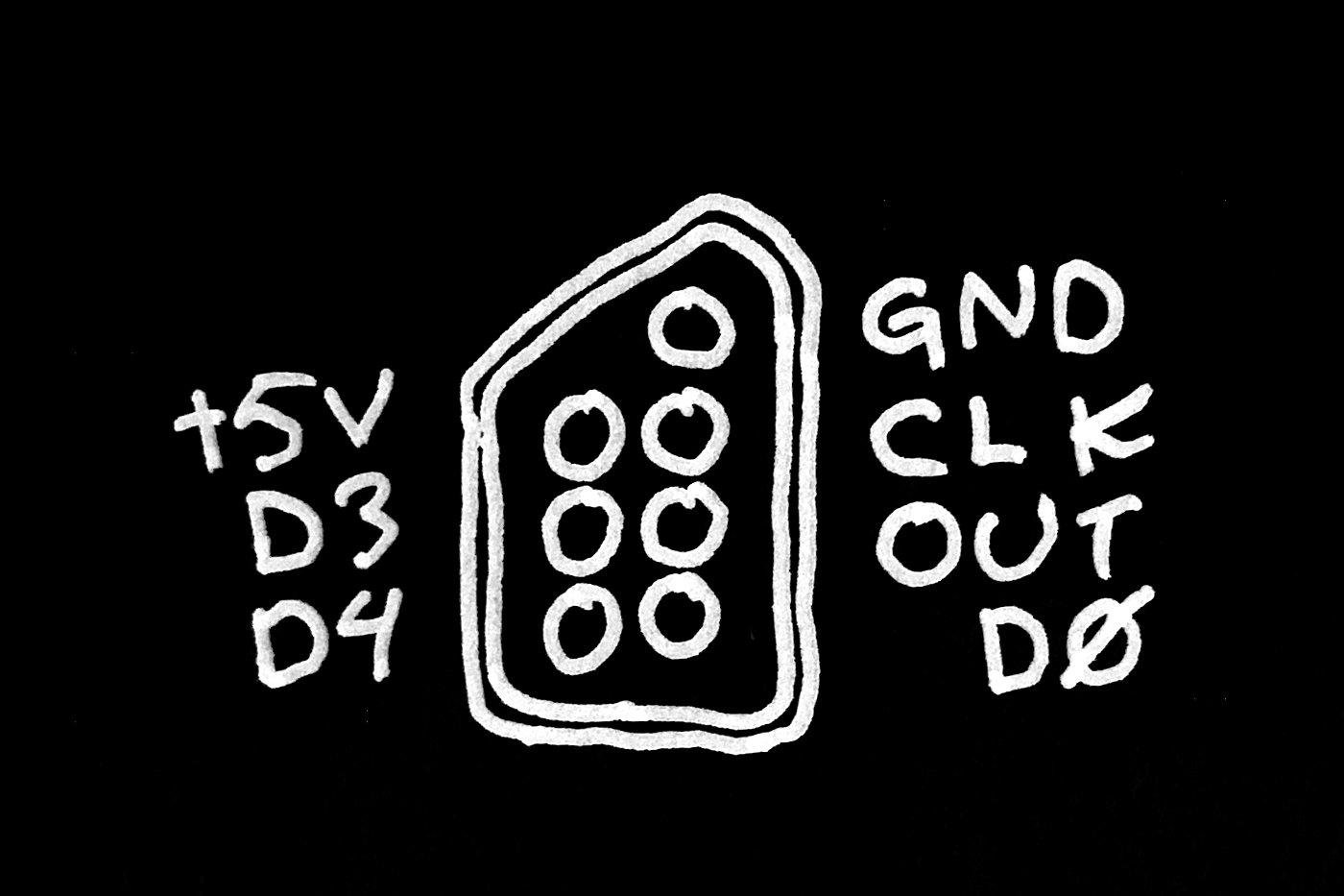
But all kids longing to play Tetris, Mario or Zelda using a joystick are left disappointed. Until now! Introducing Joy Boy – just connect it to the EXT. port and play your favorite games* using a stick and large, comfortable buttons. How cool is that?!

"Hmm …", you might be thinking, "this Joy Boy seems like a pretty dumb and useless machine. Why hack together a joystick for a 30-year-old handheld video game console? Seems rather pointless."  You are correct!

Nobody needs a joystick for the Game Boy®. It's useless because:

  • it's about 20–30 years late to the party
  • Joy Boy is hard to play on the go, like on a crowded train
  • there are no games compatible with the Joy Boy

This project is just for the lols and also my entry to the MacroFab Design Contest: Useless Machine Sponsored by Mouser Electronics.

* Not all games are compatible with the Joy Boy accessory. In fact, at the time of writing, none are. Hopefully, future games will have support after developers hear about Joy Boy.

nes-to-gb-adapter-schematic.png

NES to Game Boy Adapter Schematic.

Portable Network Graphics (PNG) - 49.04 kB - 08/30/2019 at 14:03

Preview
Download

joy-boy.gb

Homebrew demo showing button presses and stick moves.

gb - 32.00 kB - 08/31/2019 at 12:59

Download

joy-boy.asm

Source code for the homebrew demo above.

asm - 2.98 kB - 08/31/2019 at 12:57

Download

Makefile

Makefile that builds joy-boy.gb from joy-boy.asm using rgbds.

makefile - 1.14 kB - 08/31/2019 at 12:57

Download

nes-controller.ino

Arduino NES Controller Interfacing Using SPI. Only used for testing.

ino - 2.75 kB - 08/14/2019 at 16:38

Download

  • 1 × Game Boy Should work with Game Boy, Pocket, Color and Advance.
  • 1 × Zinger Joystick for the Nintendo Entertainment System by Beeshu Inc.
  • 1 × Game Link Cable Connects the Zinger with your Game Boy after some modification.
  • 1 × Flash cart Flash carts enables playing homebrew software on Game Boy. I'm using EverDrive-GB by Krikzz.
  • 1 × 74x1G04 Inverter gate needed as the Game Boy and Zinger expects different clock polarity.

  • Introducing the World's First Joystick for Game Boy

    Sven Dahlstrand08/31/2019 at 11:40 0 comments

    I made it. The Joy Boy has seen the day of light. Now anyone can play their Game Boy using a joystick. Anytime, anywhere.

    Finally, you're playing with power. Stick power!

  • My Work Environment, Tools, and Resources

    Sven Dahlstrand08/30/2019 at 17:07 0 comments

    Hardware and software tools, making development a lot easier.

    Us humans tend to love creating and make use of our tools. They are essential in almost everything we do. We are also fans of standing on each other's shoulders, taking advantage of the knowledge and resources accumulated by the ones who came before us.

    I want to share whit you some of the tools and resources that made up my working environment under this silly project, aiding me in the pursuit of making Joy Boy a reality.

    Hardware tools

    Let's kick it off with the NES to Game Boy Adapter: my handcrafted custom tool for connecting any NES controller, like a Zinger, to the EXT port on a Game Boy. In the photo above, you notice it attached to a Game Boy Advance and a joystick. See Inverter Simulation and Moving To Protoboard for a closer look at the adapter board.

    Also attached to the adapter is the probes of a logic analyzer – the Saleae Logic 8. I've used it a lot during this project to peek at the signals and get their timings just right. Without it, I would have fumbled around in the dark.

    On the subject of signals, to generate them I need my code running on the Game Boy. There's a handful of ways to make that happen, but I'm using the EverDrive-GB. It's a cartridge that slips right into the Game Pak Slot of the Game Boy and enables executing homebrewed software from an SD card. Super smart!

    Software tools

    Before running custom software on the Game Boy, it has to be authored and assembled. For that, I'm using Sublime Text as my editor of choice, rgbds for assembling and Make for managing the build process.

    I'm a big fan of Make as a tool. In this project, I wrote the sd target, so when running make sd in the terminal, it builds the whole project and copies the resulting ROM file to an SD card. If no card is present, it patiently waits. After the file is successfully copied over the card is automatically unmounted. That sort of thing saves me from much manual typing in the terminal.

    BGB is a Game Boy emulator and debugger that helps a lot during development. It's a Windows application but runs fine under Wine. For fast and easy access to documentation, I'm using Dash. If you take a close look at the photo, you'll catch a glimpse of Logic, the software accompanying Logic 8 for signal analyzing.

    Great resources

    There's no shortage of great material out there when it comes to Game Boy development and hardware tinkering.

    The Ultimate Game Boy Talk gives an excellent overview of the Game Boy's architecture and Internet Archive host the official Game Boy Programmers Manual that contains everything you need to get started developing for the handheld. Section 2.5.1 Serial Cable Communication was crucial when figuring out how to communicate with the Zinger.

    After all these years the Game Boy Community is alive and kicking, visit https://gbdev.github.io to discover more resources and fellow Game Boy nerds.

  • Inverter Simulation and Moving To Protoboard

    Sven Dahlstrand08/30/2019 at 13:46 0 comments

    An inverter turned out to be an okay solution to the polarity problem. My parts bin lacked anything even remotely looking like a NOT gate, so I implement my own using an ATtiny85. Try to find a dedicated 74x1G04 chip if you are following along and building this yourself at home.

    /*
      Performs the Boolean function Y = Ā, a quick and dirty simulation of an
      inverter gate. Please don't use this. Buy a 74x1G04 IC [0] instead.
    
      [0]: https://www.mouser.com/Semiconductors/Logic-ICs/Inverters/_/N-5820b?Keyword=74%3f1G04
     */
    
    const int IN_PIN  = 2;
    const int OUT_PIN = 3;
    
    void setup() {
      pinMode(IN_PIN, INPUT);
      pinMode(OUT_PIN, OUTPUT);
    }
    
    void loop() {
      boolean pinInState  = digitalRead(IN_PIN);
    
      digitalWrite(OUT_PIN, !pinInState);
    }
    

    With that fixed, I have a fully working connection between any Game Boy and Zinger Joystick (or any NES or SNES controller really). Until now, I have experimented on a breadboard, but I grew tired of the messy state it was in, so for a more permanent installation I took the time to move everything over to a protoboard.

    NES to Game Boy Adapter protoboard. Don't pay the wire color choice to much attention. I intended to match the wire colors inside the Zinger cable, but I messed that up.

    I call it the NES to Game Boy Adapter and you should be able to throw one together yourself by having a look at the schematic.

  • Polarity Sucks

    Sven Dahlstrand08/15/2019 at 10:06 0 comments

    Do you remember me telling you about both the Zinger (or any NES controller for that matter) and the Game Boy communicates using not quite SPI, but close enough. That's still true. However, I was naive thinking the two could have a conversation without an interpreter.

    The problem resolves around clock polarity and the fact that the NES controller expects the clock signal to be idle low while the Game Boy thinks it should be idle high. Polarity 0 in one end, 1 in the other. That's no good.

    There's no way for me to change the polarity from firmware, so additional hardware is probably needed. In the best-case scenario throwing an inverter (NOT gate) on the clock signal should suffice.

    If you need to brush up your SPI skills, as I did, What Could Go Wrong: SPI by Elliot Williams is a great read.

  • SNES success

    Sven Dahlstrand08/13/2019 at 22:38 0 comments

    SNES controller with relevant pins connected to Arduino Uno.

    Yes, I found my old SNES controller and, yes, it uses the same communication protocol as the NES controller and, by extension, the Zinger. In other words: it is a decent substitute until a working joystick shows up.

    First thing I did after unearthing the controller, was to figure out its pinout. I ended up learning the order of things from the Schematics, Ports, and Pinouts page at the SFC Development Wiki. There's no fancy drawing this time, just this photo:

    SNES controller plug pinout. From left to right: GND, NA, NA, D0, OUT, CLK, +5V.

    SFC Development Wiki provides different signal names compared to the ones at wiki.nesdev.com; using data, latch, and clock instead of D0, OUT, and CLK. I like the former, more descriptive ones, better. Next, I hooked up the controller to the Arduino Uno and ran my test program.

    Lo and behold, it worked. I made contact! What does that mean? That I'm able to show current controller state, which buttons are held down at any moment, in a serial monitor on my Mac.

    Finally, I've made progress.

    Serial monitor and source code windows. Each serial output line represents a change in the controller state. It's me, pressing buttons!

    What you see in the screenshot above is the result of me pressing buttons frantically during a test session. The controller state fits in a single byte, each bit representing one of the buttons. Can you guess which buttons I pressed in each case with just the screenshot as your guide? There's a hint in the source code window.

    On the subject of source code, my test program is pretty simple. On a high level, it implements the NES controller protocol using the Arduino's SPI hardware. At roughly 60 Hz the controller is asked nicely to latch the button state into its shift register and start delivering bits until a full byte is received.

    That byte is sent out on the serial line for me to marvel at in the monitor.

    I won't go into more details here. The source file is short (< 100 lines) and heavily documented, so I strongly suggest anyone interested to take a closer look and study it.

    It's great to be on track again. Now, time to focus on the Game Boy.

  • Stuck and unstuck

    Sven Dahlstrand08/12/2019 at 18:35 0 comments

    I like keeping my workbench tidy and organized. Sometimes it doubles as our dining table.

    Given how much time I've spent troubleshooting, I'm a little disheartened it didn't get me anywhere. I still haven't been able to communicate with the joystick from an Arduino.

    Today I, once again, took a screwdriver to the Zinger and tore it down. This time around, I took a closer look at the circuit board and snapped a couple of photos.

    Front and back of the printed circuit board. It's virtually just buttons and switches connected to an IC.

    Next, I grabbed my multimeter and made sure everything was hooked up the way I expected it to be. No shorts circuits or other nasty surprises. I took note of the single integrated circuit on the board and which of its pins each wire ended up at.

    Partial pinout of the integrated circuit identified as MDT 5022N.

    Markings on the IC yielded no result when searching the interwebz. Lacking a proper datasheet, I can never be 100 % sure I've made the right assumptions concerning the pinout. Maybe I got it wrong somehow, and that's why I can't get data off the joystick.

    Anyhow, with the PCB exposed I connected the pins directly to my logic analyzer and Arduino Uno and started running my test program – I'll get into more details in a future log entry – and, just as before, the clock (CLK) and latch (OUT) signals from the Arduino to the joystick looked okay, but the data signal (D0) from the joystick was flat. No matter what.

    That's it, I'm stuck. At least with this particular joystick. Maybe it tanked during my investigations or perhaps it was already broken when I bought it. (I never confirmed with an actual NES that the joystick actually worked.)

    To move forward, I need another Zinger to experiment with. Or some other interim controller, utilizing the NES protocol, like an original NES or SNES controller. I lack the former, but the latter is actually in my possession. Somewhere.

    Maybe I'm not stuck, after all.

  • Bad news and good news

    Sven Dahlstrand08/11/2019 at 09:14 0 comments

    I've got some bad news and some good news to deliver. Let's start with the bad.

    I missed the August 10 deadline for the "Useless Machine" contest.

    The good news is that Macrofab decided to extend the deadline to 31st. Yay!

    Neither good nor bad is the fact that my initial efforts at communicating with the joystick, utilizing an Arduino board, were fruitless. The data line is silent, no matter what I do to the stick and buttons. Maybe I messed something up during my teardown?

    I should team up with a multimeter and logic analyzer next.

  • Crafting breadboard friendly cables

    Sven Dahlstrand08/10/2019 at 12:48 0 comments

    I want to start interfacing the joystick already. However, I'm not quite there yet. I need an easy way to connect the joystick to an Arduino, maybe a logic analyzer, and, of course, an actual Game Boy. In my previous log entry, I described the decapitation of the joystick cable – the removal of its NES connector. After that treatment, it's hard to use the joystick even as intended, connected to a Nintendo Entertainment System.

    In cases like this, I tend to strip the wires inside the cable and attach jumper wires to them. The result is the breadboard friendly cable shown in the header image.

    Jumper wires stripped and prepared with heat-shrink tubing. Everything is ready for the next step: twisting and soldering the wires together.
    The blue wire before and after the joint is soldered and covered with shrink tube.

    That's it! Later on, I will need something similar at the Game Boy end: a breadboard friendly Game Link Cable. Luckily that's something I already made for myself a couple of years ago using the same method described above.

    The vivid breadboard-Game Link Cable hybrid by yours truly.

  • A colorful plug teardown

    Sven Dahlstrand08/10/2019 at 08:55 0 comments

    After a good nights sleep and breakfast, I reached for my wire cutter and cut off the NES connector from the joystick cable. There are five wires inside the cable, color-coded as black, white, blue, green and brown. I had no idea what color corresponded to wich signal. What I do know is the NES controller port pinout, thanks to the hard-working Nesdev community. With that information, I pried open the plug to figure out the relationships between wires and pins.

    So, without further ado, I'll present to you my findings. Be careful though: I can't guarantee all Zinger joysticks are wired the same way or using the same colors as mine.

    The Zinger plug pinout

    Name

    Wire color
    GNDBrown
    CLKBlue
    OUTWhite
    D0Green
    +5VBlack
    D3Not present
    D4Not present

    Black for +5V and brown for GND? Not the most obvious choices of color if you ask me.

    The plug seems happy enough, even after my brutal treatment.

  • A strange-looking robot pirate

    Sven Dahlstrand08/10/2019 at 00:04 0 comments

    The Zinger is sold as a Nintendo Entertainment System (NES) accessory and connects to the controller socket. For the joystick to be compatible with every NES game, it should pretend to be an ordinary NES controller.

    If that's the case, I'm in luck because the standard controller is well documented and basically just a big parallel-in to serial-out shift register.

    I don't want to destroy my Game Boy for this to work, so I have to interface the joystick unobtrusively. Fortunately, every Game Boy come equipped with an External Extension Connector – EXT for short. Have you ever used a Game Link Cable to trade Pokémons with other kids at school? That cable goes to the EXT connector.

    The port consists of 6-pins and, according to my interpretation of the Game Boy Programming Manual, it works pretty much like an SPI (Serial Pheripial Interface) device without a slave select line.

    "Hey! Isn't a shift register just that?", you might think, "A peripheral device, communicating over a serial line. Maybe … the Zinger and the Game Boy can understand each other. Really well."

    Yeah, that's my thought as well. Great minds think alike and all that.

    However, the plug at the end of the Zinger cable is too big to fit into the EXT connector. My plan right now (given that my assumptions above turn out to be correct) is to cut away the NES plug from the Zinger cable. Then slice a Game Link Cable in half, merging one of the halves with the Zinger cable. That should yield me a joystick with a cable and plug that fits right into the EXT connection on a Game Boy.

    Reasoning about all this is part of what I did since the last log entry. I also cracked open the Zinger and peeked inside.

    Some plastic Zinger parts. I throw them out on the floor, and they randomly formed this strange-looking robot pirate. Spooky!

    Opening the case was easy enough. Seven screws, and that's it. Two wires connecting the stick and PCB prevents a total disassembly, however, unless you're up for some desoldering.

    There's not much going on here. I count to one integrated circuit, probably containing the shift register and some circuitry to handle the "Quick Fire" functionality.

    When the joystick was all in parts, I seized the opportunity and gave most of the plastic pieces a bath. Probably the first one in a long time. The Zinger is a lot cleaner now and smells goodish.

    There's more work to be done before this is a success:

    • Remove the plug from the joystick and replace it with pins for easy breadboarding.
    • Get a hold of a Game Link Cable with pins suitable for breadboarding (I have one laying around from earlier projects).
    • Try communicating with the joystick (using an Arduino) to confirm my shift register theory.

    After that, I should be able to write a Game Boy homebrew that interfaces with the joystick.

View all 11 project logs

Enjoy this project?

Share

Discussions

Game Boy Camera wrote 01/05/2023 at 03:55 point

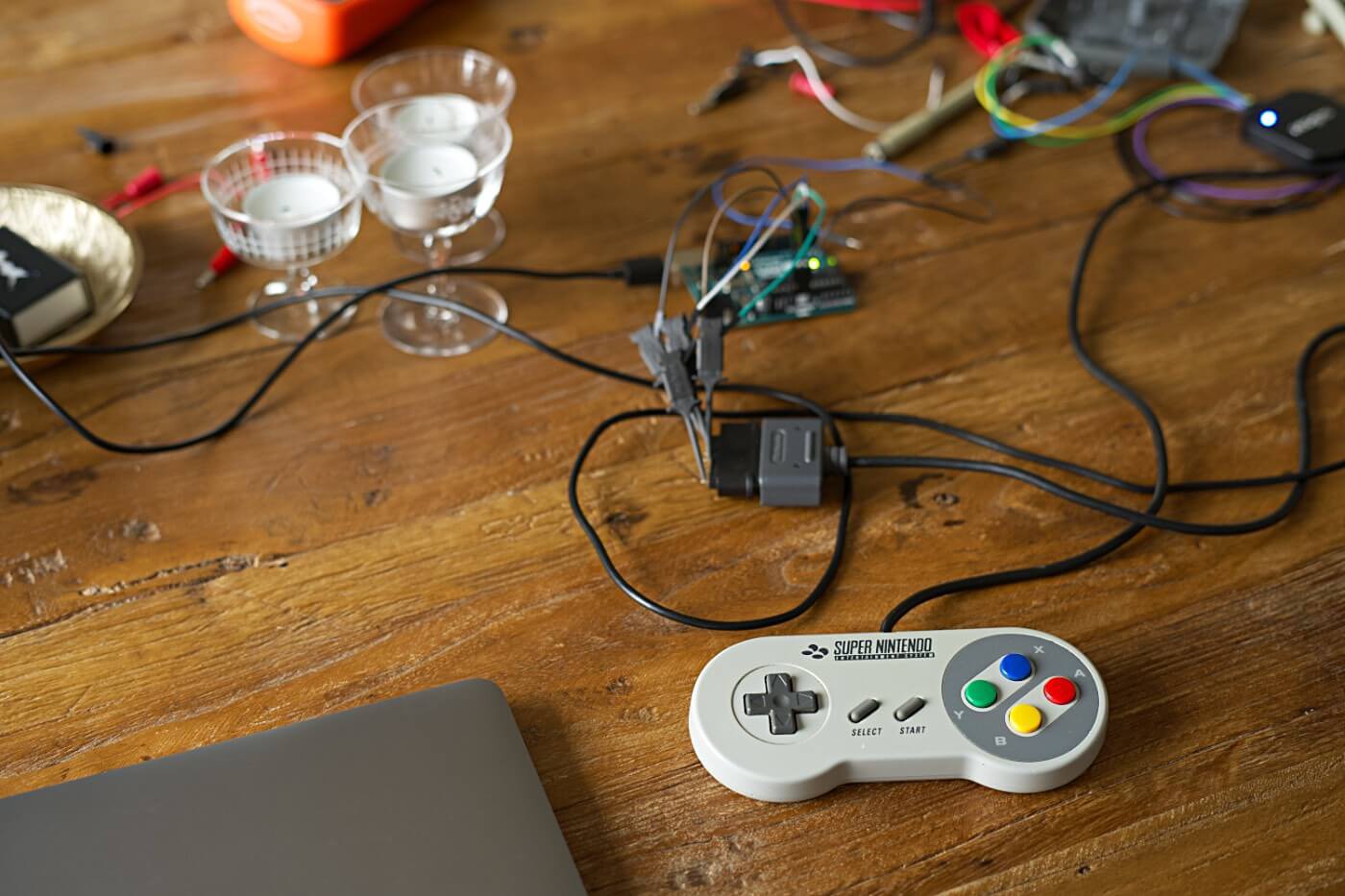
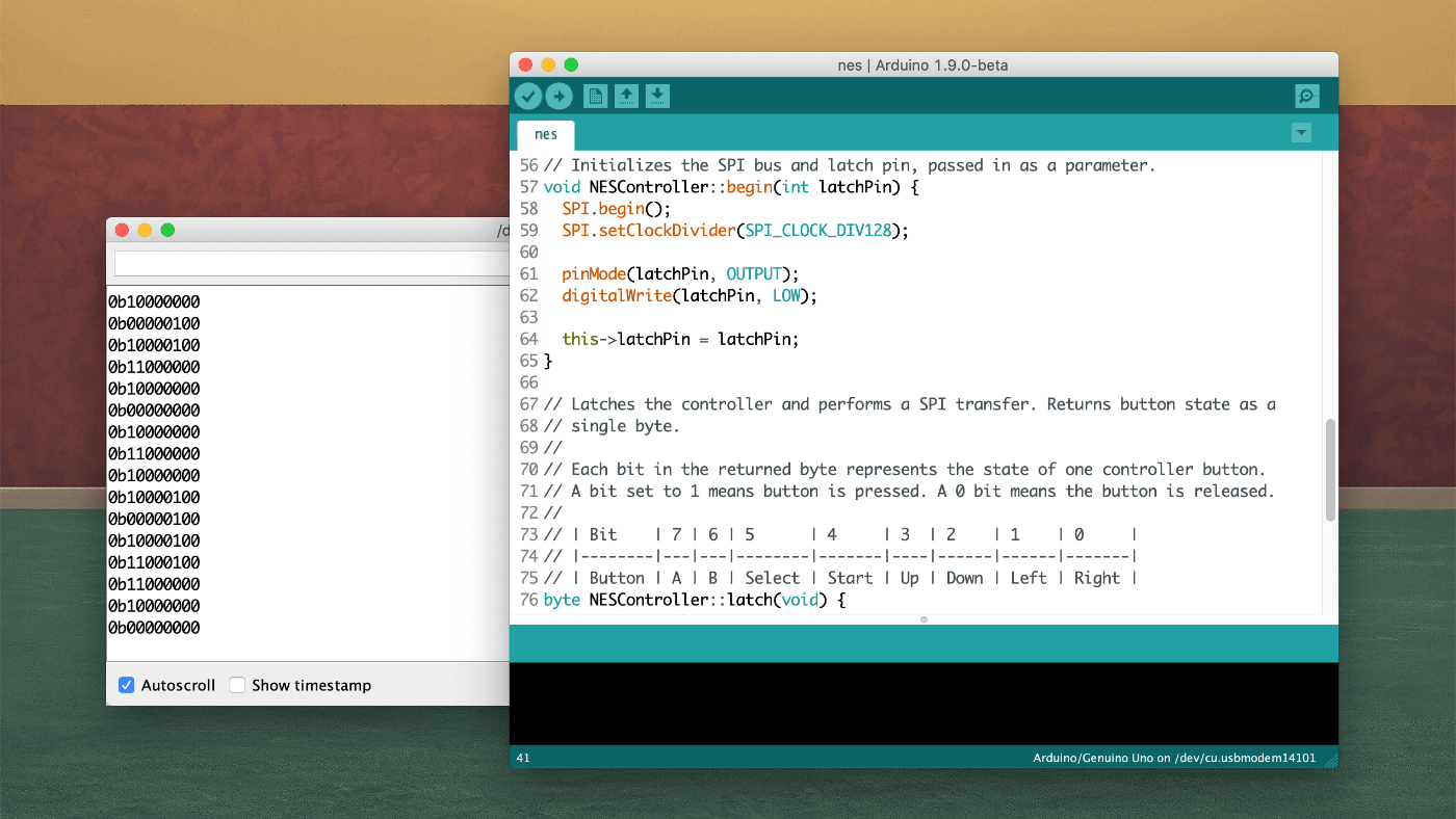
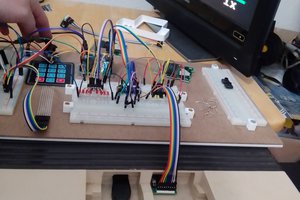
Really cool! I did a similar project (with some help) with an NES controller recently! The intention was to interact with the a homebrew Game Boy Camera ROM remotely.

https://github.com/gameboycamera/NES-controller-to-GB-linkport

  Are you sure? yes | no

Tom Nardi wrote 08/10/2019 at 03:05 point

Interesting project. Would it be possible to patch ROMs to make use of the joystick, or is the idea just for it to work with homebrew?

  Are you sure? yes | no

Sven Dahlstrand wrote 08/10/2019 at 07:00 point

Thanks, Tom. Yeah, I think it's doable and a great idea, and I've experimented with something similar in the past. I patched Super Mario Land to accept incoming serial packages, from my Mac, that let me modify the game on the fly: like giving myself extra lives. 

I'm a little torn about the idea, though, as this project is my entry to a "Useless Machine" contest. I would love to hack some of my favorite games, adding support for the joystick, but, in doing so, the project wouldn't be that useless anymore.

  Are you sure? yes | no

Sven Dahlstrand wrote 09/02/2019 at 20:52 point

Super Mario Land now has support for the joystick. :) I have to polish it a little before releasing the patch, but there's a video available here: https://vimeo.com/357417602.

  Are you sure? yes | no

Similar Projects

Does this project spark your interest?

Become a member to follow this project and never miss any updates