 Sven Dahlstrand
An inverter turned out to be an okay solution to the polarity problem. My parts bin lacked anything even remotely looking like a NOT gate, so I implement my own using an ATtiny85. Try to find a dedicated 74x1G04 chip if you are following along and building this yourself at home.
/*
  Performs the Boolean function Y = Ā, a quick and dirty simulation of an
  inverter gate. Please don't use this. Buy a 74x1G04 IC [0] instead.

  [0]: https://www.mouser.com/Semiconductors/Logic-ICs/Inverters/_/N-5820b?Keyword=74%3f1G04
 */

const int IN_PIN  = 2;
const int OUT_PIN = 3;

void setup() {
  pinMode(IN_PIN, INPUT);
  pinMode(OUT_PIN, OUTPUT);
}

void loop() {
  boolean pinInState  = digitalRead(IN_PIN);

  digitalWrite(OUT_PIN, !pinInState);
}
With that fixed, I have a fully working connection between any Game Boy and Zinger Joystick (or any NES or SNES controller really). Until now, I have experimented on a breadboard, but I grew tired of the messy state it was in, so for a more permanent installation I took the time to move everything over to a protoboard.
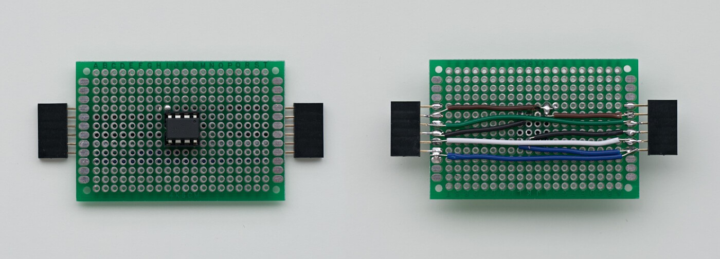
I call it the NES to Game Boy Adapter and you should be able to throw one together yourself by having a look at the schematic.
Discussions
Become a Hackaday.io Member
Create an account to leave a comment. Already have an account? Log In.