 B K
B KThe design currently contains four modules, including:
- Base module (with NodeMCU, breakout headers, 74HCT125N level shifter and external connectors/spots for DHT22 sensor)
- Power Supply module (with AC/DC, DC/DC and POE-level power supply options, to provide the 5V power for the stack)
- Analog/Digital IO module (offering expansion of Digital I/O up to 128 signals and 4 channels of 16-bit ADC analog)
- OLED/AmbiMate sensor module (offering a 0.96" OLED screen for local sensor data display and support for the multiple sensor AmbiMate MS4 board from TE Connectivity)
The different boards can be stacked in any order (with OLED board on top, of course), and multiple ADIO boards can be stacked together to expand I/O up to 128 channels.
The Kube v2 supports typical ESP8266 firmwares, including ESPEasy, as well as my original Kube firmware (with minor changes for pin layout). With ESPEasy, the different sensors and OLED screen can be easily connected to home automation platofrms like openHAB or HomeAssistant via MQTT.
Boards
This section will describe the currently available Kube module boards in detail, including schematics and any jumper settings required for each board, as well as links to the parts required to build each module.
1. Kube Base Module

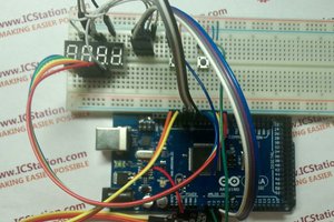
The Kube Base module is the only required board in the Kube stack. It contains the headers for a NodeMCU v0.9, v2 (LoLin v3 works, but won't fit the enclosure), as well as breakout headers for all of the NodeMCU pins. With just the Kube Base module, a NodeMCU, a DHT22 sensor, and an OLED screen, you can create this sensor:

The base module contains the following features/headers:
TOP: (NodeMCU side)

| Device | Usage | Notes |
|---|---|---|
| EXT | Used for external sensor connections, e.g. HC-SR501 PIR motion sensor (D5 NodeMCU pin) | VCC pin is tied to JP1, sourcing either 3.3V or 5V DC |
| JP1 | Selects 5V or 3.3V supply voltage for the EXT header | Does not affect D5 pin voltage range |
| IC1 | 74HCT125N 4-channel fast level shifter | Used for I2C/LED and EXT signal pins; Great for LED pixels |
| D1 | BAT43 Schottky Diode | Used between RST and D0 pins on the NodeMCU to prevent boot-up issues during flashing |
| DHT | DHT22 Temperature/Humidity sensor | Used when base baord is used as a remote temperature/humidity sensor; uses D6 pin on NodeMCU |
| I2C/LED | I2C bus connector header, to allow daughter-boards to connect to the Kube base board and to each other | Has both 5V and 3.3V pins, GND, SCL (D1) and SDA (D2), as well as an additional digital I/O pin (D4), commonly used in LED strip controller firmware |
BOTTOM:

| Device | Usage | Notes |
|---|---|---|
| D1BYP, D2BYP | Used to shift (to 5V via IC1) or bypass (3.3V from the NodeMCU) the I2C Clock (D1, SCL) and Data (D2, SDA) pins within the I2C/LED header | Solder middle pad to either the SHFT (for 5V) or BYP (for 3.3v) pads. |
| D4BYP | Used to shift (to 5V via IC1) or bypass (3.3V from the NodeMCU) the D4 LED pin within the I2C/LED header | Solder middle pad to either the SHFT (for 5V) or BYP (for 3.3v) pads. |
| D5BYP | Used to shift (to 5V via IC1) or bypass (3.3V from the NodeMCU) the D5 EXT pin within the EXT sensor header | Solder middle pad to either the SHFT (for 5V) or BYP (for 3.3v) pads. |
The full schematic for the Kube baseboard is shown below:

2. Power Supply Module

The Kube Power supply submodule offers several options to provide the 5VDC power required to run the NodeMCU and the entire Kube stack. It is generally not required, since it's perfectly fine to power the Kube with just a USB power supply via the NodeMCU's micro-USB port (accessible via a hole in the base module's enclosure), but if you're going to use more sensors, IO boards, or other external devices, it is recommended to supply power to the Kube stack via this PSU board module.
The Kube PS board module provides three possible configurations, each allowing different input voltages, with 5V DC output.
- Using a MeanWell IRM-03-5 AC/DC power supply (110VAC...
 icstation
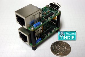
 Alexander Williams
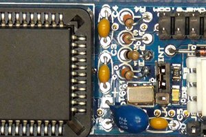
 Bil Herd
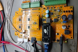
 steve
steve
I like what you've done with your submodules. Thank you for including jumpers on the OLED board for assigning Vcc/GND and SDA/SCL to the four pins. I have different SSD1306 displays that have the pins assigned every which way. Why someone couldn't have standardized the I2C pin assignments is beyond me. It's only four pins! Grrrr...
Anyway, about the OLED submodule, it seems to put a big old ground plane right above the ESP8266's WiFi antenna. Does attaching the board degrade WiFi connectivity?
Thanks