 Mihai Oltean
Jenny 5 is an (almost) humanoid robot intended to be used mainly for research but also as a human assistant. More details about Jenny 5 can be found at: https://jenny5.org or https://jenny5-robot.github.io.
Jenny 5 was inspired by the Johnny 5 robot from the Short circuit movie. This a great movie that anyone must see.
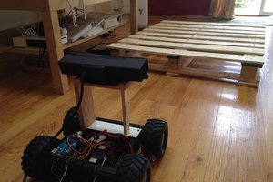
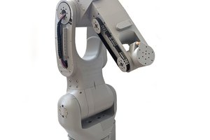
Jenny 5 has a mobile platform with tracks, a pliable leg, two arms with 7 degrees of freedom each and one head
All source files (CAD, software etc) for Jenny 5 are freely available on GitHub. All code is released under MIT license so that anyone can freely use it in both personal and commercial applications.
Jenny 5 is easy and cheap to build. Most components can be purchased from robotics stores. Custom made parts can be printed with a 3D printer. Some aluminium profiles can be cut and drilled with tools available for hobbyists.
Materials (excepting the computer) cost about 2500 USD (please see the Bill of materials for more details).
Jenny 5 is designed in OpenSCAD which is a CAD software where you write instructions, instead of using the mouse, to create objects.
The platform is driven by 2 DC motors with planetary gearbox controlled by a RoboClaw board.
The leg is driven by 2 linear motors controlled by a RoboClaw board.
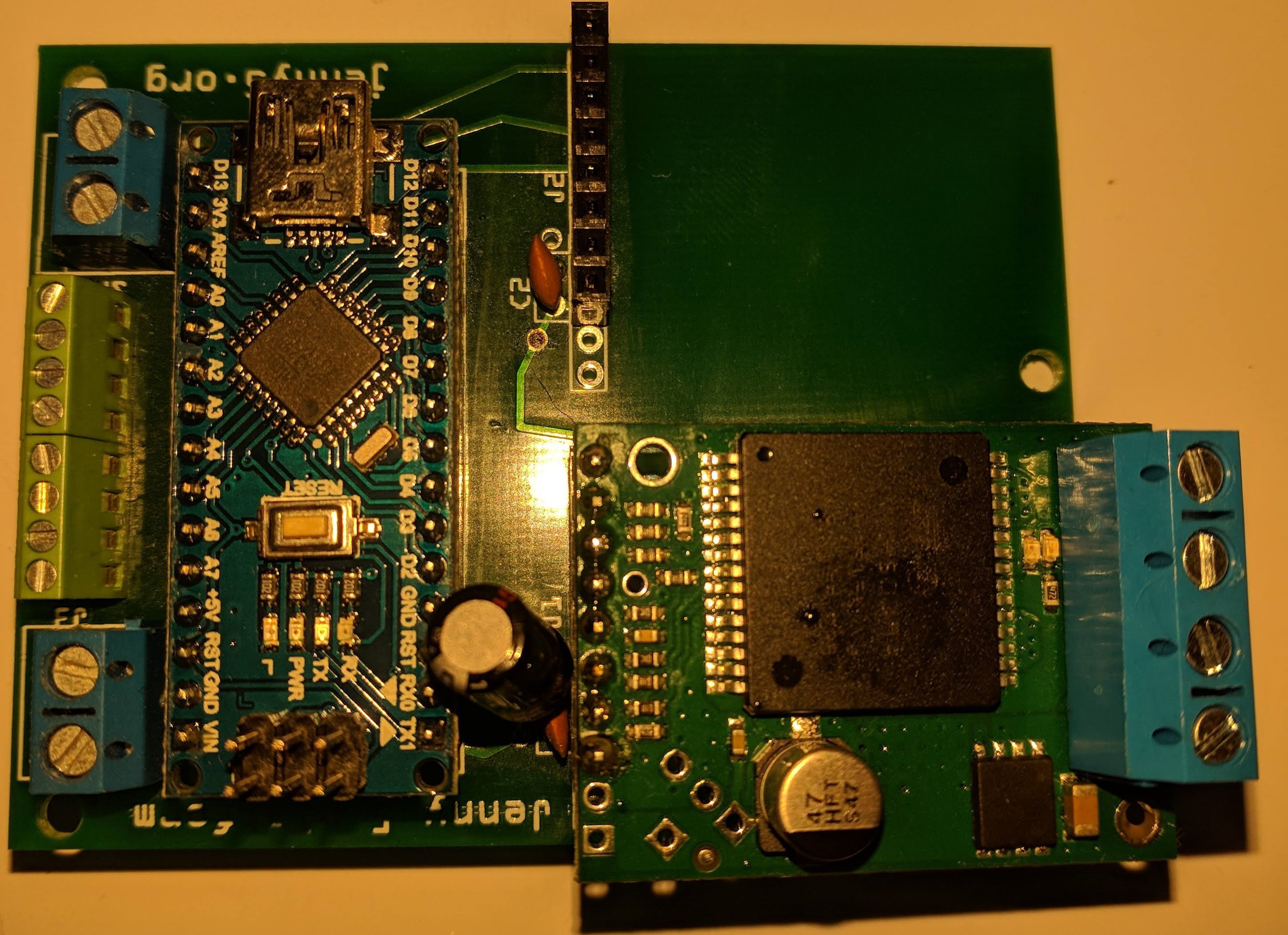
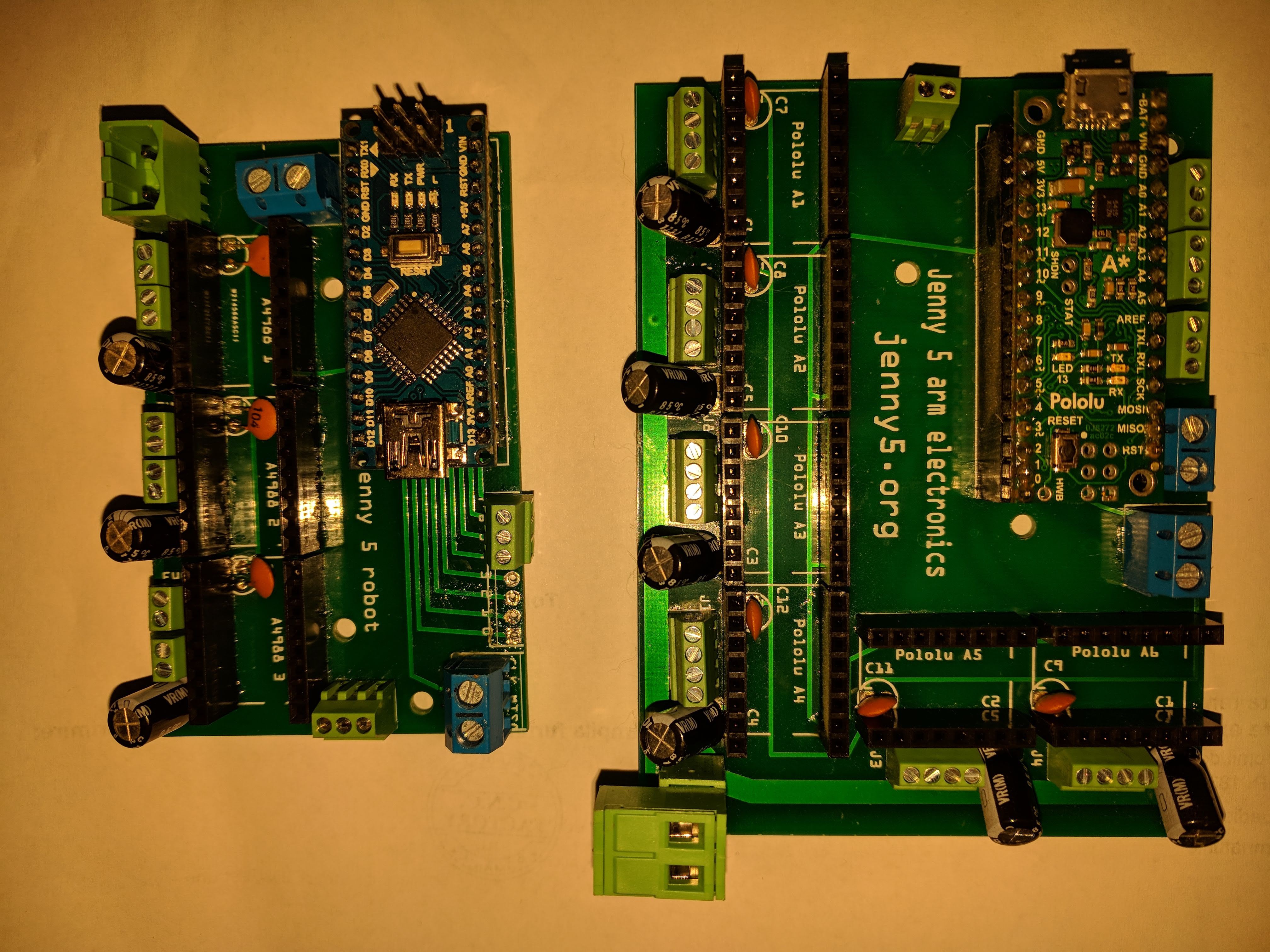
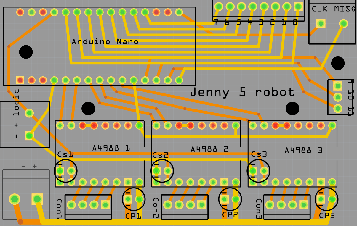
Each arm has 6 stepper motors and each joint has attached a magnetic sensor for reading its position. Motors and sensors are controlled by an A-Star 32U4 Miniboard.
The gripper is powered by a servo motor. The gripper is connected to the same A-Star 32U4 Mini board as the entire arm. The gripper has attached a webcam used for recognising objects closed to it.
The head has 2 degrees of freedom ensured by 2 stepper motors which have magnetic attached for reading the position. The head has a webcam for object detection and an ultrasonic sensor for distance measurement. All head components, except the camera, are connected to an Arduino Nano board.
The entire robot is powered by 2 LiPo batteries: one for platform and foot and one for arms and head.
A-Star / Arduino boards run a specially crafted firmware called Scufy which is able to control multiple stepper motors and read a variety of sensors: buttons, ultrasonic, potentiometers, infrared, LIDAR etc.
PC software is built around several libraries which send commands, on a serial port, to A-Star/ Arduino boards and to the RoboClaw controller.
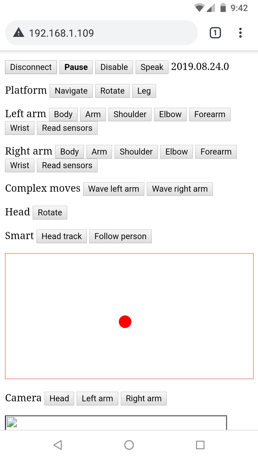
The robot can be manually controlled by an HTML5 application running within browser on a smartphone. The HTML5 application connects with a server running on the robot. The server is the one that actually execute the commands(move, read sensors) etc. The server is built on a top of a light WebSocket server.
Having all these elements, the robot can be utilised in a wide range of scenarios. Here is a short list of things that the robot could do (if programmed correctly):
- House cleaning
- Food preparation
- Cleaning kitchen table
- Working in the garden
- Surveillance
- Rescue
- Disaster management
- Fire fighting
- ...
For more details please read the technical report about Jenny 5.
You can also subscribe to Jenny 5 Google group
 Shawn Chen
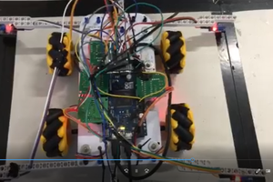
 Miguel Wisintainer
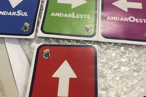
 Petar Crnjak