Close
0%
0%

NSX-64

MSX adapter for Nintendo 64 controllers

Similar projects worth following
This project lets you play MSX games using Nintendo 64 controllers. The several N64 controller buttons are mapped on a variety of combinations for the MSX and the analog stick can act both as directional controls and as standard Paddles.

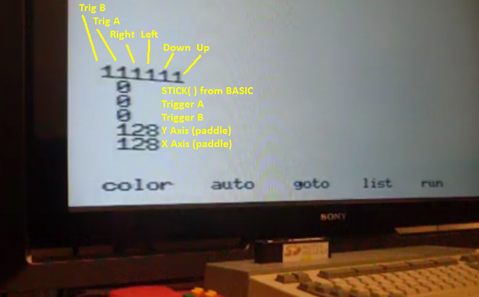
Nintendo 64 controller is read by NicoHood's Nintendo library and the buttons are converted to MSX equivalents according to the table below.

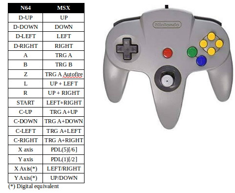
Analog stick is mapped to MSX controllers using a paddle emulation function that responds to an interrupt that is generated by a rising edge on pin 8 (pulse) of joystick port.

The tricky part of this project is that Nintendo64 reading library has a time critical portion that takes about 157us with interrupts disabled, then if a paddle reading pulse arrives while the AVR is sampling the N64 controller, the interrupt service routine will be neld by up to 157us, which correscorresponds to 8 out of 255 counting loops performed by MSX to read the paddles. Too much time!

The solution is based on a premise that whenever a program will read the paddles to do something useful, it will do it periodically, usually at the video vertical sync frequency (50/60Hz depending on the MSX origin country ).

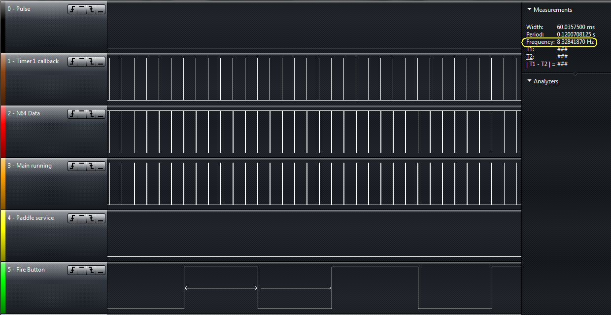
Here is how the code is wrapped:

  • The main loop will sample the N64 controller and update the AVR outputs accordingly. Then the cpu will sleep.
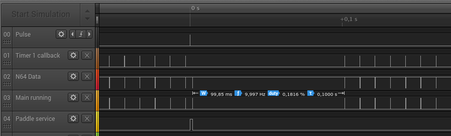
  • A second interrupt will be used, attached to Timer 1 which is set to interrupt at a interval of 10ms. This interrupt solely wakes up the processor and set the interrupt AGAIN for a 10ms interval

Whenever an external interrupt occur, it will:

  • reinitialize the Timer 1
  • set a NEW period of Timer overflow to 100ms
  • Do the paddle emulation

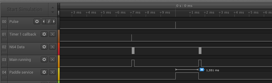
Summarizing, the Timer 1 wakes up the AVR after a variable timeout. When no paddle reading pulses are coming the timeout is 10ms.

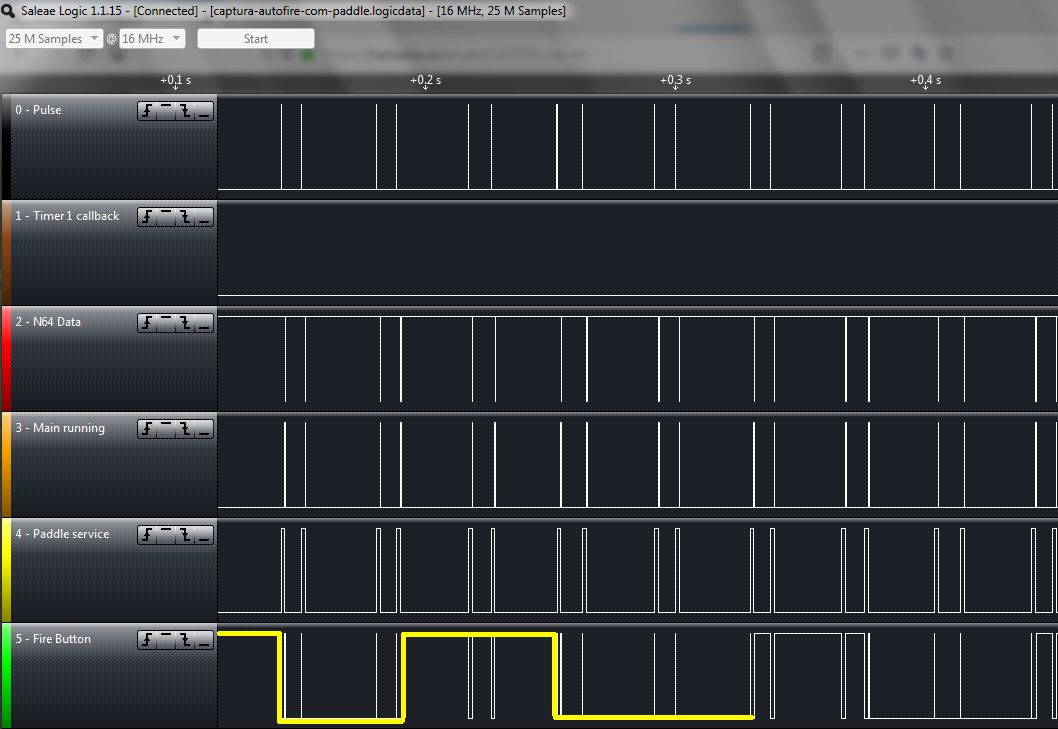
First paddle reading pulse set a new (100ms) timeout interval, which is longer than the usual 16.67/20ms expected for a game loop (even in a BASIC program).

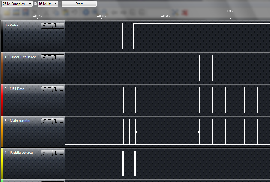
Consecutive paddle reading pulses (within 100ms) reinitialize the timer so no timeout occurs while paddle is being continously reading.

100ms after the paddle reading pulses cease, the timeout will occur to wake up the CPU and the timeout period will be restablished as 10ms.

  • 1 × Arduino Nano
  • 1 × Sega Megadrive extension cord
  • 1 × Nintendo 64 extension cord
  • 1 × 560 Ohms resistor

  • Demonstration Videos

    danjovic08/19/2019 at 03:09 0 comments

    First video is a test program written in BASIC language:

    Second video is a brief gameplay of Zanac. Video shoot is terrible as I was playing the game with one hand and hold the camera with another (both videos were did like that)

    It is possible to notice some lag from the analog stick and the ship moving in the screen.  As the controller is being sampled at 100Hz (10ms) this lag is not caused by software, it is caused by the time I spent to move the stick to the opposite position until it passes a given threshold around the center. It can be reduced either by lowering the threshold value or by deducing the movement direction by the rate of change of the analog stick.

  • First working version!

    danjovic08/18/2019 at 01:12 0 comments

    After implement the autofire using a DDS technique to make the autofire work (more on that later) I have the first full working version ready. Source is available at Github.

    The autofire function modulates the TRIGGER A button at 8 Hz with duty cycle very close to 50%.


    When Paddles are being serviced it is possible to observe3 the envelope of the autofire modulator.


    Worth to mention that both captures have been done with Z button continously pressed to generate TRIGGER A + AUTOFIRE

  • Timeout/Interleave interrupt logic working OK

    danjovic08/15/2019 at 04:00 0 comments

    Arduino library ecosystem come in handy but sometimes you better read the datasheet and write your own code.

    After I have spent a lot of time struggling with TimerOne library,  trying to figure out why the function to change the period weren't working I gave up and started to write my own code. Didn't need to write it from scratch, as I found most of the code that I needed from a AVR timer calculator .

    The code snipped turned into a function:

    #define _10ms 2499     // OCR1 values for timeout
    #define _100ms 24999
    
    ///////////////////////////////////////////////////////////////////
    // Timer 1 timeout configuration
    //
    inline void setTimer1 (uint16_t overflowTicks) {
       cli(); // disable interrupts
       TCCR1A = 0; 
       TCCR1B = 0;
       TCNT1  = 0; // initialize counter value to 0
       OCR1A = overflowTicks; // set compare register 
    
       TCCR1B |= (1 << WGM12);                     // CTC mode
       TCCR1B |= (0<<CS12)|(1<<CS11)|(1<<CS10); // prescaler = 64
       TIMSK1 |= (1 << OCIE1A);                 // ISR Timer1/Compare
        
       sei(); // enable interrupts
    }

    And it worked flawlessly:

    The first image shows the Timer 1 callback running at 10ms (brown trace) until a paddle read pulse arrived (black trace). Then the paddle service runs (yellow trace) and the return from paddle service (interrupt) causes the cpu to wake and perform a new reading of the n64 controller (red trace). Right after that, the CPU sleeps again but this moment  the interval for the Timer to call the callback have changed to 100ms.

    If no other paddle reading Pulse arrives within 100ms the Timer 1 callback service reprograms the interval to 10 ms and the sampling continues at 10ms intervals.

    On the other hand if paddle reading Pulses keep arriving within and interval of 100ms the Timer 1 callback starves.

    In other words... Success!!


  • Progress

    danjovic08/13/2019 at 23:29 0 comments

    Button activation logic is OK now! The adapter is already usable to play games!

    Todo:

    - Autofire (button Z),

    - Timeout logic.

  • Running code on actual hardware

    danjovic08/12/2019 at 01:59 0 comments

    Running the code on real hardware I have found some stuff

    • Arduino Timer 0 shall be powered off before enter interrupt, otherwise it will wake up processor (and we don't want that)
      void loop() {
        do_N64(); // Sample  and Update Outputs
        digitalWrite(debugPin2,LOW);   // debug
        // put AVR to sleep
        set_sleep_mode(SLEEP_MODE_IDLE);
        sleep_enable();
        power_timer0_disable(); // Arduino keeps this timer running
        sleep_mode(); 
        sleep_disable();  
        digitalWrite(debugPin2,HIGH);   // debug
      }
    • Button activation logic still still need some working
    • I will probably have to use Timer 2 to modulate autofire

    Working now to find why Timer 1 does not change the timeout value to 100 ms after the paddle interrupt service.

View all 5 project logs

Enjoy this project?

Share

Discussions

Similar Projects

Does this project spark your interest?

Become a member to follow this project and never miss any updates