 Maarten Janssen
For the displays I used 3 common cathode 3-digit displays for a total of 9 digits. I wanted to keep the number of pins needed to control the display to a minimum and ended up requiring just 3 pins to control the displays; 2 pins for SPI (MOSI and SCK) and 1 pin to give the display an initial reset RST.
For each digit one byte of data is sent over the SPI bus to a 74595 serial in, parallel out shift register. The first 4-bit counter of a 74393 is clocked using the SCK to count the 8-bits of SPI data. After the 8th bit has been received it will latch the data to the output of the 74595, it provides a clock pulse to the second 4-bit counter of the 74393 and it resets itself.
The second 4-bit counter of the 74393 is used in combination with two 74138 1 of 8 decoders to select the active digit. The highest bit of the counter selects between the two decoders and the lower 3 bits will be decoded to pull one of the outputs of the two 74138s low.
The 8 data lines of the 74595 are connected to the anodes of the display segments and the outputs of the 74138s are connected to the digit cathodes of the displays. To reset the digit counter the 4th output of the second 74138 is inverted and fed into the reset of the second counter of the 74393.
A simple diode OR-gate is put in front of the reset inputs of the counters to allow both the Arduino and the internal display logic to reset the counters.
The Arduino software is very simple since it only needs to put the display in an initial state by resetting it and then it can send the data for each of the displays in order.
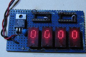
The display works, but it has its drawbacks. The Arduino needs to continuously scan the display to provide a stable image. Also these logic gates are not capable of driving the displays very well; when all segments of a digit are on then that digit is noticably dimmer. This could probably be solved with a bunch of transistors, but I don't want to take it that far...


 Hulk
Hulk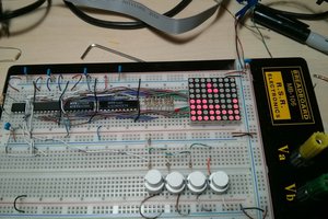
 Kevin Cuzner
Just a thought: You could also use a shift register for the cathode drive. All you need is an initial pattern of 1111111110 to turn on one digit, and to shift this left every cycle, and repeat. There are high current versions of the 595.