 matop
matopWheel speed estimation
Each hall encoder produces nb_{rising edges} logical rising edges per motor rotation (due to multiple magnetization points on encoder ring).
Speed estimation relies on counting the number of logical rising edges nb_{encoder ticks} during an known time interval dt for a single sensor.
Wheel speed is then estimate with the following relation
At low speed, the signal is noisy and filtering is applied. The filter consists in a running average with higher weight on the last value. Some tuning on filter size and weights might be needed.
Wheel direction estimation
In order to estimate direction, during each rising edges of sensor A, the logical state of sensor B is read. Then a logical state is associated with a direction.
This method is quite robust but sometimes presents glitches which are removed using a median filter.
Control strategy
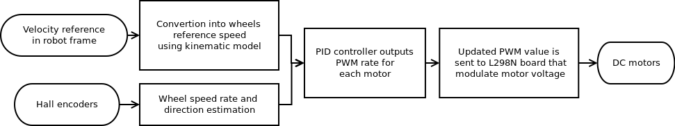
Linear and angular reference velocity in the robot frame are converted into left and right wheel reference speed using differential drive kinematics model.
http://www.cs.columbia.edu/~allen/F17/NOTES/icckinematics.pdf
Then a PID controller tends to make estimate speed converge to reference speed for each motor. PID's output is not directly PWM value but PWM rate.
Controller tuning
Tuning controllers could be painful and require basic understanding on effects of each Proportional, Integral and Derivative terms. To accurately tune your controller you will need to log several debug variables while playing a step reference input.
The ROS package called plotjuggler offers a complete UI for real-time visualization and logging of topics values. Simply publish debug topics with interesting values.
- Set I=0 and D=0, progressively increase P until motor get a response with a "important" overshoot (more than 50% of a step respons. Debug variables: reference speed, estimated speed, PWM rate, PWM value
- Motor response time could be long, to reduce this increase progressively D value. Be aware that this term tends to amplify noise. Debug variables: reference speed, estimated speed, PWM rate, PWM value, PWM rate from Derivative term
- At this point, PWM value might vary a lot, try to smooth it by adding Integral term
Results
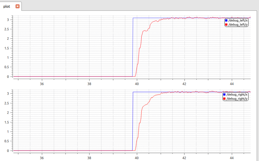
Plotting reference angular rate in blue and estimated angular rate for both motors give the following performances:
- settling time 95% = 350ms
- static error = 0
Control and estimation loop frequency
This section presents some 'business rules' that will help you to tune your controller loop and filters.
The controller frequency should be at least twice higher than your robot dynamics bandwidth (less than 5Hz for turtlebot-like robot), so running that loop at 50Hz should be able to produce a good stability and rapidity control.
The speed wheel estimation frequency should not exceed twice the minimal desired speed. From the equation given at Wheel speed estimation, it is possible to calculate the corresponding frequency.
About filter: note that delay is your worst enemy, it reduces rapidity and stability. So the more you filter raw encoders value, the more you add delay into control.
Discussions
Become a Hackaday.io Member
Create an account to leave a comment. Already have an account? Log In.