 matop
matopFirst Layer
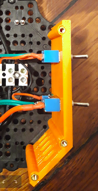
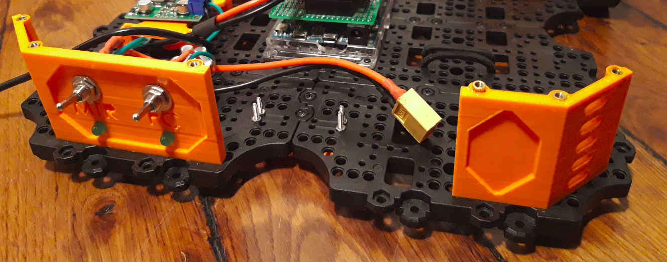
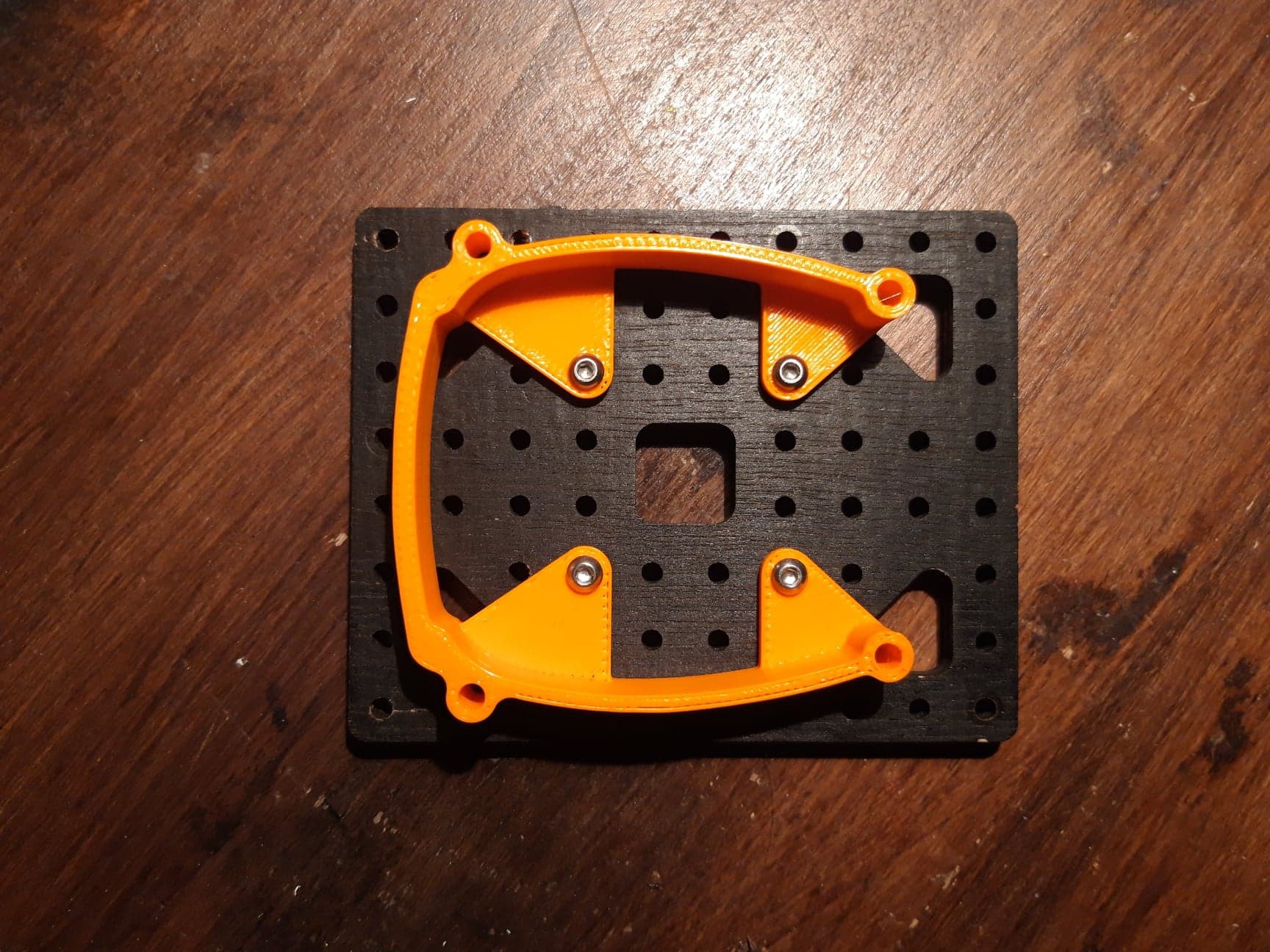
Switches holder
I use two switches, one to power the SBC and another one to power motor. They come with they respective LED that indicates which device is on.
The plate that hold them also serves as spacer to support the upper plate. A symmetrical plate without switches and narrower to allow battery passage completes the structure.
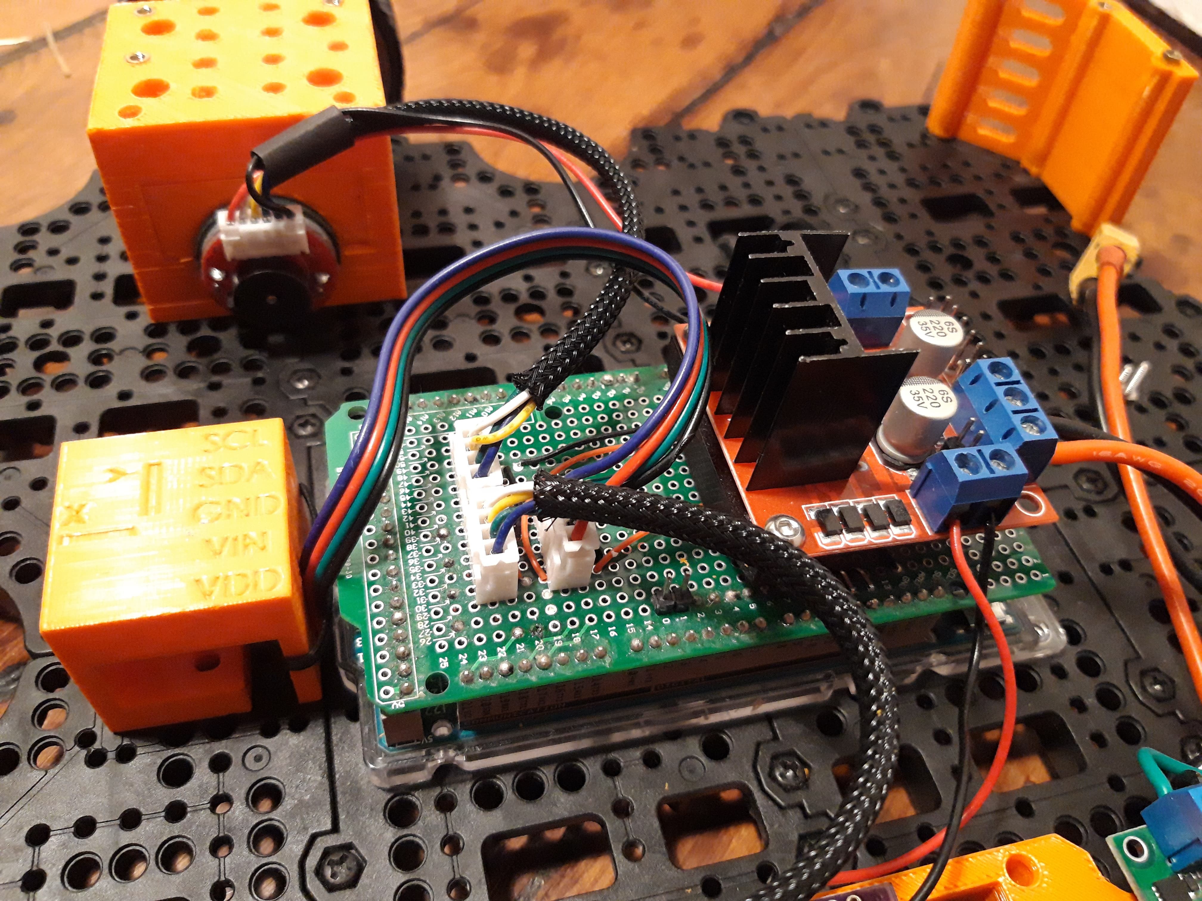
Electronic boards holder
Electronic boards are kept slightly elevated from the first layer thanks to a 3D printed 'table'. This part allows cables to pass under and reduces the 'messy aspect' near switches and battery.
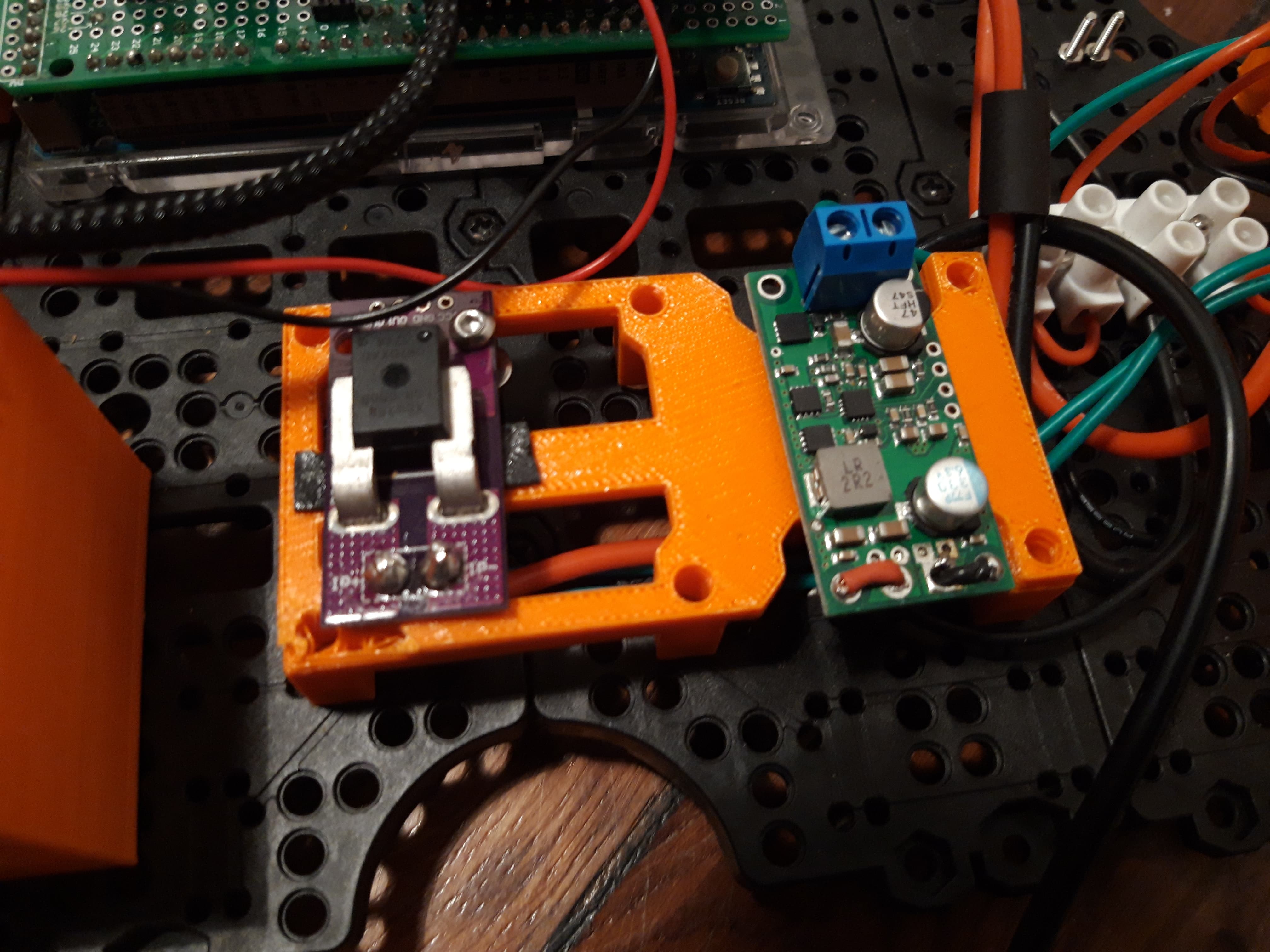
Double sided tape is used to maintain boards. You can find the CJM CU 758 current sensor and the 5V pololu regulator.
Others
Basics 'bornier' are used to dispatch power.
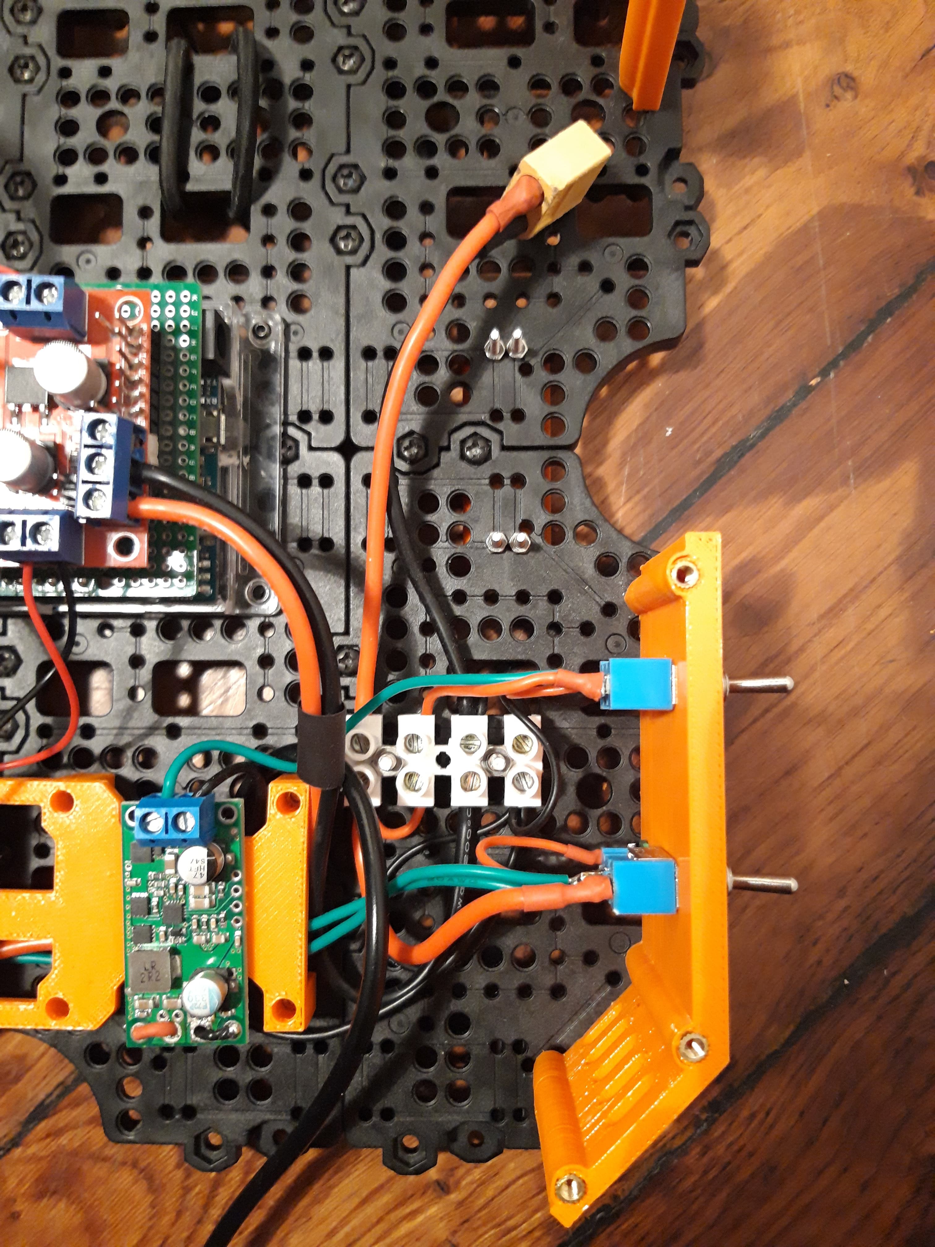
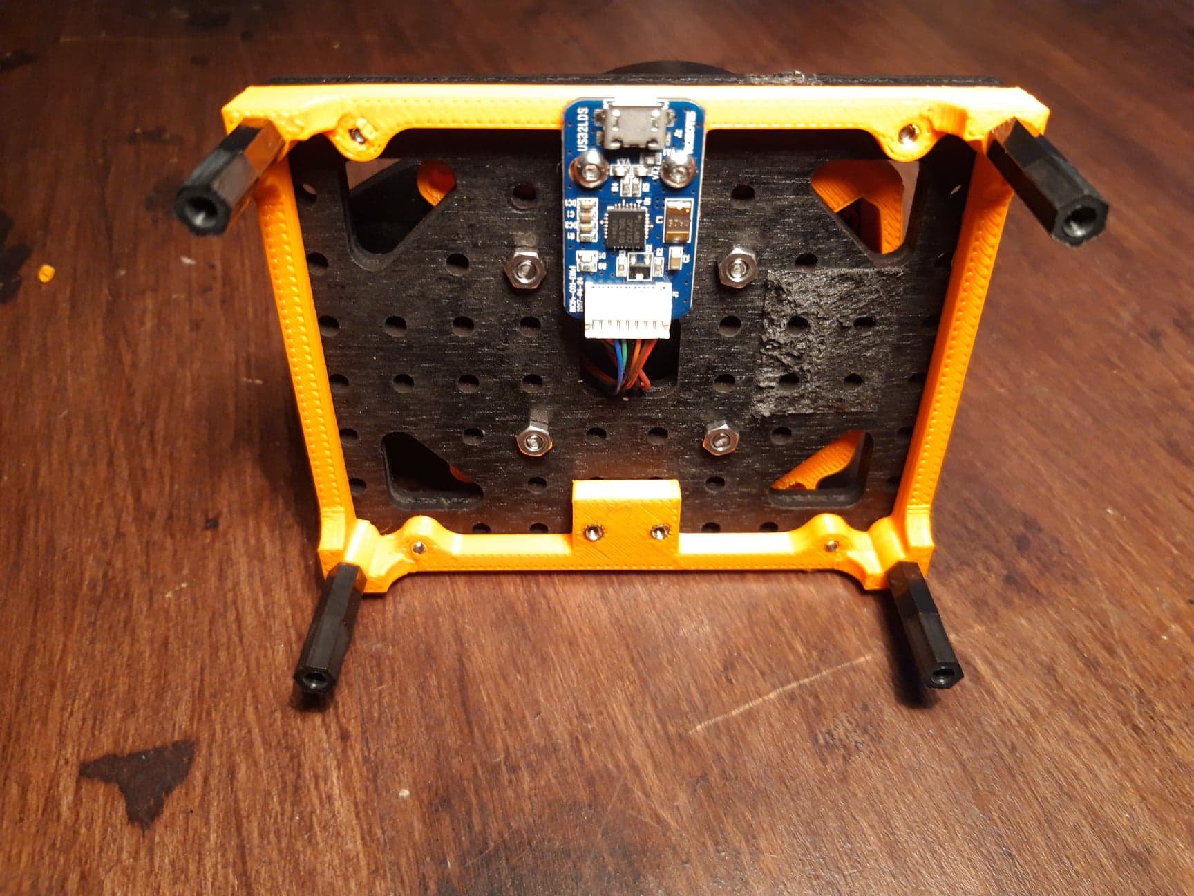
IMU holder is fixed at the current center of rotation of the platform: namely the middle of the 'motor line', it may be defined as the center of the platform in the future.
Second layer
As the project slowly drifts into building a complete robot platform which is needed to test and validate TB3 packages, I present you parts related to 'higher level' components, located on the upper plate.
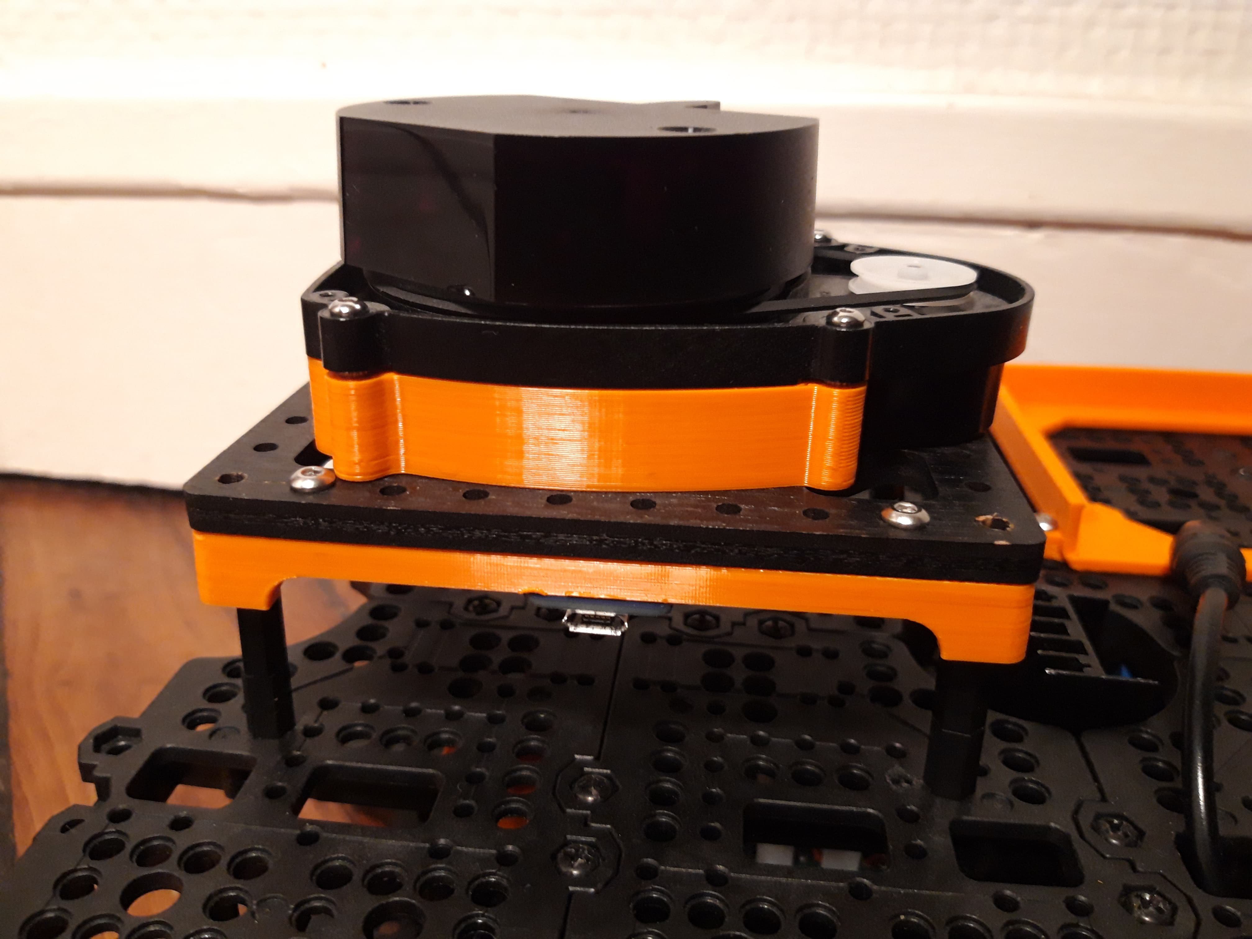
Lidar mount
In order to elevate LIDAR from the upper plate, I use an intermediate wooden plate (but could be 3D printed) on which a specific part as been design to match shapes of the LDS01 LIDAR. To gain height, nylon spacers and a adaptation part are used.
Discussions
Become a Hackaday.io Member
Create an account to leave a comment. Already have an account? Log In.