 Matias N.
Last few days I made some considerable advances so this will probably be a long post. TLDR: trackpad works!
Trackball
First thing I received was the blackberry trackball evaluation module. Since my expectation was that it would not be very accurate as a mouse replacement, I limited myself to simply analyze what was the actual resolution of the device. After connecting my cheap-o logical analyzer to the relevant outputs, I could see that there were around 9 pulses per one complete sweep of the finger on the ball (ie. the maximum that you could move the finger in one move). If you count edges, you then get about 18 counts. As expected this is a bit low. In fact, I tested only slightly moving the finger and indeed it required a bit of motion to get the first pulse.
In conclusion, this kind of interface is more to either replace a mouse scroll wheel or for other kind of projects altogether. For example, it could be used for navigating a GUI displayed on a small screen, avoiding the need for four buttons.
Trackpad
Now this is where it gets interesting. I was eager to try these modules and see what could I get from them. I bought four units: two BB9900 trackpads, and two BB9800. As mentioned in the previous log, these have 13-contact flexible PCB connectors. From my research, these present a I2C interface, instead of the SPI used in other models. Still, it was supposed to implement a similar register map than that of ADNS3060 optical mouse sensors. One extra difficulty in these models, though, is that it requires both a 2.85v supply for the sensor itself and 1.8v for the logic. This of course also means it requires a level-shifter to map 3.3v <-> 1.8v.
So, the first task was to solder some tiny wires to the connector and make a DIP-like module for it, so that I could place it on the breadboard. While I actually had a digital microscope on the way, I gave it a try in soldered the wires with the naked eye. I must say it ended up quite nice. Here's a picture with the microscope of the job done:
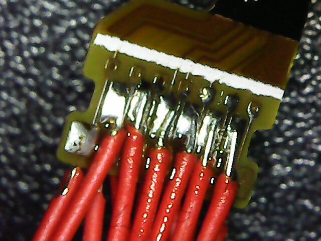
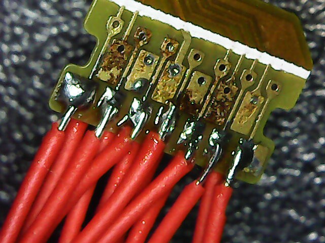
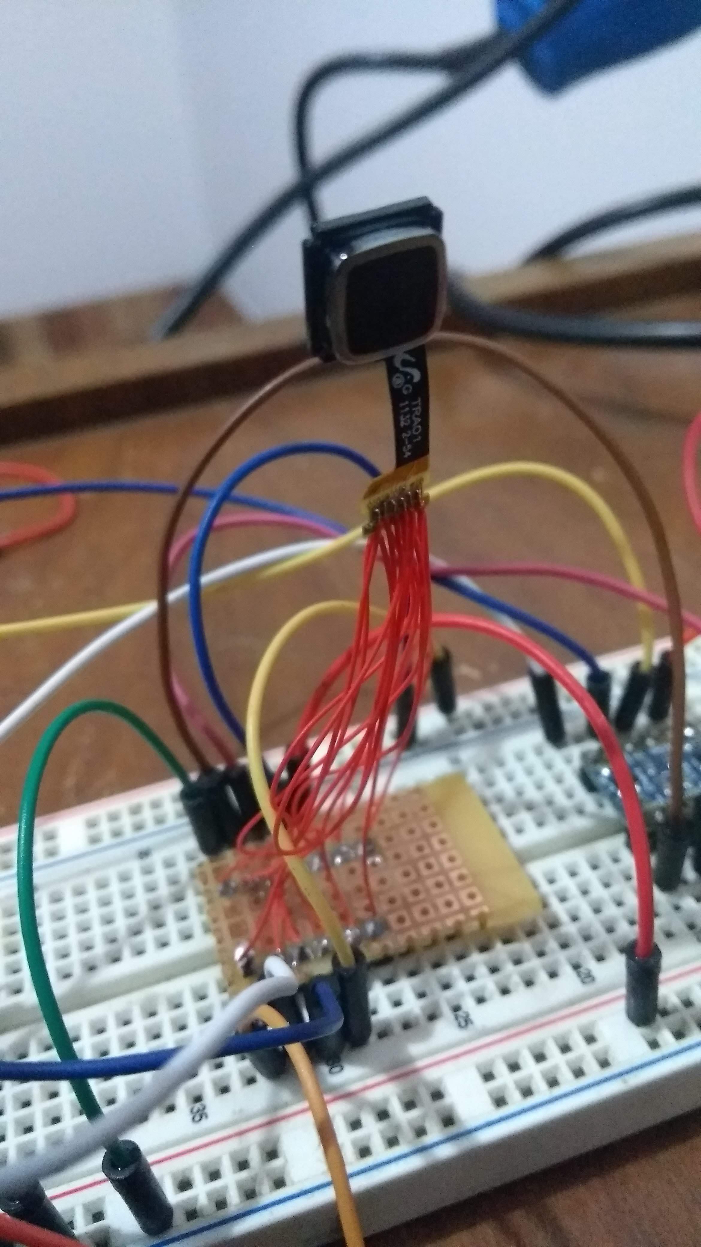
The brown part is some leftover flux. Or maybe it is a bit of burnt substrate, but it did not damage any of the fine traces. Also, I verified that there were no shorts. The module then looks something like this:
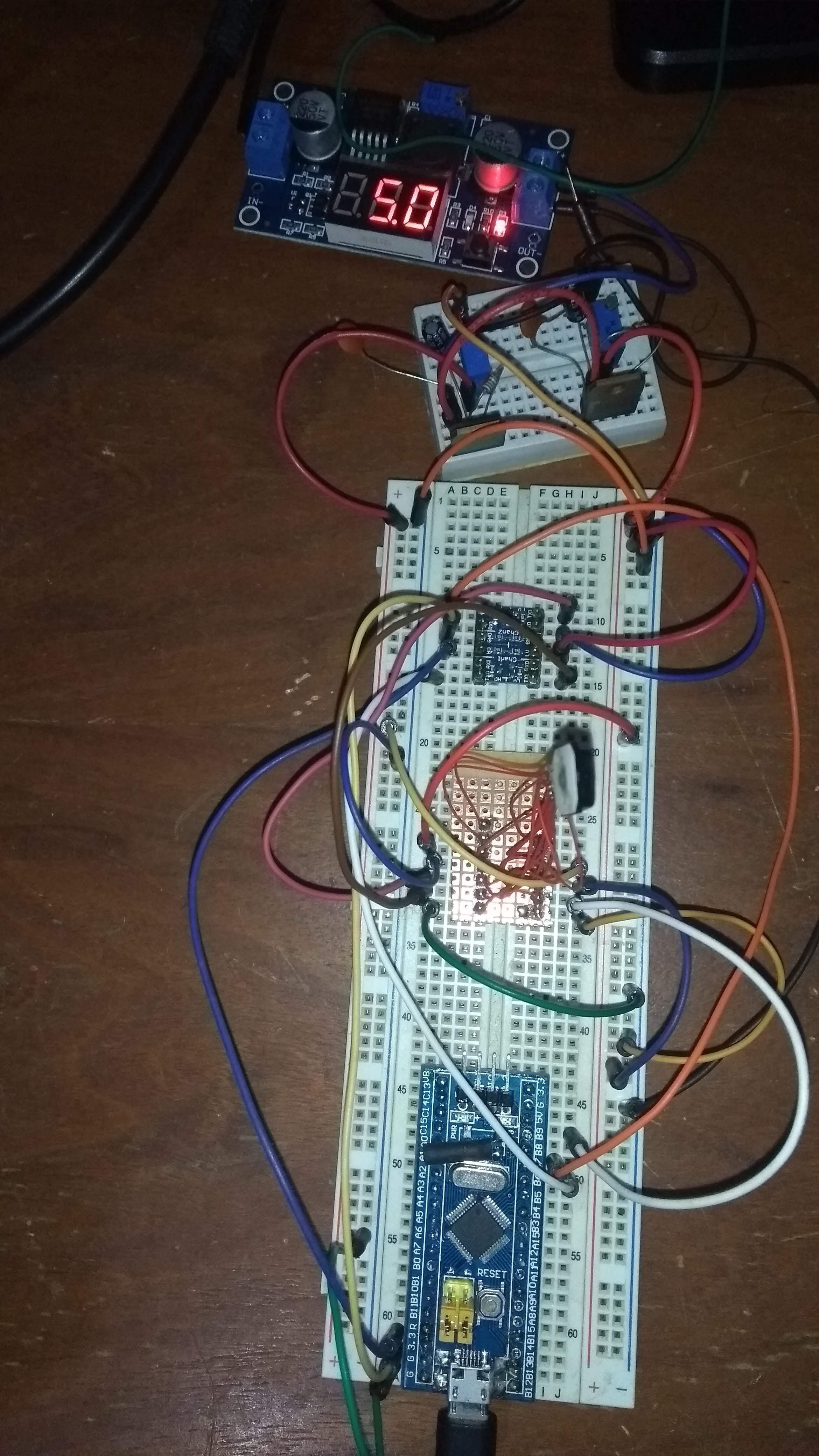
The second step was to build the pair of power-supplies. Using an switching adjustable power supply (my new low-cost bench PSU at the moment), I converted from a 12v wall adapter to regulated 5.0v. Then, I've built the 2.85v and 1.8v supplies using a pair of LM317's and a small breadboard. I then wired the supplies to the module and used the logic-level converter to map the SCL and SDA lines.
For testing I bought a BluePill board (STM32F103) but for some reason USB did not work (even after the R10 resistor fix). I then moved to an Arduino Pro Mini for initial testing. Later on, I re-used my old BluePill (which lacked the USB connecter) and transferred the malfunctioning board's connector towards the old board.
The complete test setup can be seen in the following photo:
Interfacing with the module
At first I encountered many problems which led me to think that it just was not possible to talk to the board. Maybe the pinout wasn't correct. Maybe this model was different. Anyways, after lots of trying I finally found that I had some wires setup wrong in the breadboard. But that was not all. While playing with the wires and running an I2C device scanner Arduino example, I suddenly got a response from a device with a 0x3B address. Then, after playing with the wires again I got a 0x33 address instead. At first I assumed it was noise in the line, but it was actually pretty consistent. Finally, I concluded that depending on the assigned SHUTDOWN pin value, and after resetting the module, it presented itself with either one of these addresses. I've tested for the expected motion registers and concluded that the one that worked was the 0x3B one, so I left the wires for that case.
Once I got that working it all went pretty well. From my tests, it seems that it mostly resembles an ADNS3050 actually, from the registers I got working. At the moment it appears that register 0x2 will have the 7th bit high whenever motion was detected. Thank, registers 0x3 and 0x4 can be read (separately! otherwise it does not work) to obtain a two's complement of X and Y deltas. Finally, the motion bit needs to be reset after reading these registers by writing 0 to 0x2. I also managed to set the device in 1000cpi resolution (instead of 500cpi) by changing a configuration register, which greatly improved response. I must say the device is really sensitive, and provides a nice range for fast movements. I think this is a very good mouse replacement.
Last thing I tried was to read the MOTION pin so that I did not have to poll the registers. This also worked perfectly, so everything I could need for now is there.
Next steps
I will now write a driver for the module for NuttX. I already have a driver for emulating a mouse (or any HID device) from NuttX. So by writing a simply app that reads the trackpad and writes to the emulated mouse I can have a working version. I will post again when that is done. After that, I'm thinking which direction to go. Option a) is to design a small PCB which would include the appropriate connector for the flex PCB (is that connector even standard? If you know how to track the part number, please let me know) and encloses the MCU and USB port. This would be a functional wired prototype. Another option is to continue prototyping in order to get to a wireless version (maybe Bluetooth or something NRF24L01 based). This also requires dealing with battery chargin circuit and a battery small enough to make the device small.
Discussions
Become a Hackaday.io Member
Create an account to leave a comment. Already have an account? Log In.
Hi there!
Could you please share with me a complete schematics for 9800 trackball? I am trying to replicate your work and it still does not work at all. I would like to know how you did connect all pins. Thank you!
Are you sure? yes | no