 Matthew James Bellafaire
I spent quite awhile looking through components to try to find something that fit for this project. Price was something of a concern, but there's only so much I could do since I'm only looking to make maybe 10 of these boards at max. Lets get into it, here's the full schematic:
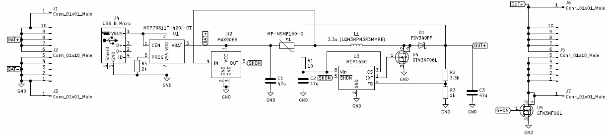
All things considered this is fairly simple but lets talk about the elephant in the room here, the multiple connectors on each side of the schematic. Since this is being designed for perfboard the final PCB will have castellated edges, in combination with the all SMD part selection the final board should sit as low as possible for convenience. All components here are use hand-solderable packages (so basically anything with pins jutting out to the side where they can be reached by an iron).
For charging this design uses the MCP73811T which is basically the cheapest lithium ion charger available on digikey in a usable package. It only charges at 500mA in this configuration but that should be good enough for most cases. Just in case it isn't the 2K resistor coming off the PROG pin can be swapped with another value to change the maximum current, according to the datasheet:

this gives the final board some flexibility, since it might be used with smaller 150mAh batteries if its just doing small things.
Next the under/over voltage protection, I really wish I could have rolled this all into a single IC but everything available that handles charging and protection is available in QFN or some form of BGA making it fairly difficult to assemble. For the the battery monitoring the MAX9065 window comparator keeps an eye on the volrage. In the event that the battery voltage passes below 3.0V or above 4.2V the comparator will pull its output low which will cause the boost converter to shut down and disable the output N-Channel MOSFET. If the comparator trips, the external circuit should be completely disconnected from the battery and prevent any further discharge. In that event the entire circuit which is connected to the battery should consume only about 600μA which will avoid any damage to the battery.
Over current protection is handled by a simple polyfuse. The polyfuse chosen here is rated for 1.5A continuous and will trip at around 3 amps (chosen since that's the maximum rating for the inductor). Additionally in the event that the polyfuse trips the voltage being sensed by the MAX9065 will go below 1 volt and thus disable the outputs and boost converter. It would be nice to have something a little more versatile that can work with any size battery for detecting a fault this should prevent any serious damage.
Finally the boost functionality, this design utilizes the MCP1650 which is a simple 750kHz boost controller, paired with a 4A MOSFET. The MCP1650 was chosen since it can start up at voltages as low as 2V making it ideal for battery applications. Here the boost circuit simply ups the voltage to 5V from whatever voltage the battery is at. This board should be able to sustain 5V @ 1 Amp over the time that the battery is charged with some additional peaks.
The next step in this project is to build up a physical prototype, but I think I'll get a jump on the PCB while I'm waiting for the components to arrive. See you in the next log!
Discussions
Become a Hackaday.io Member
Create an account to leave a comment. Already have an account? Log In.