We kick off the project midway through R&D. Here is a brief what's happened so far.
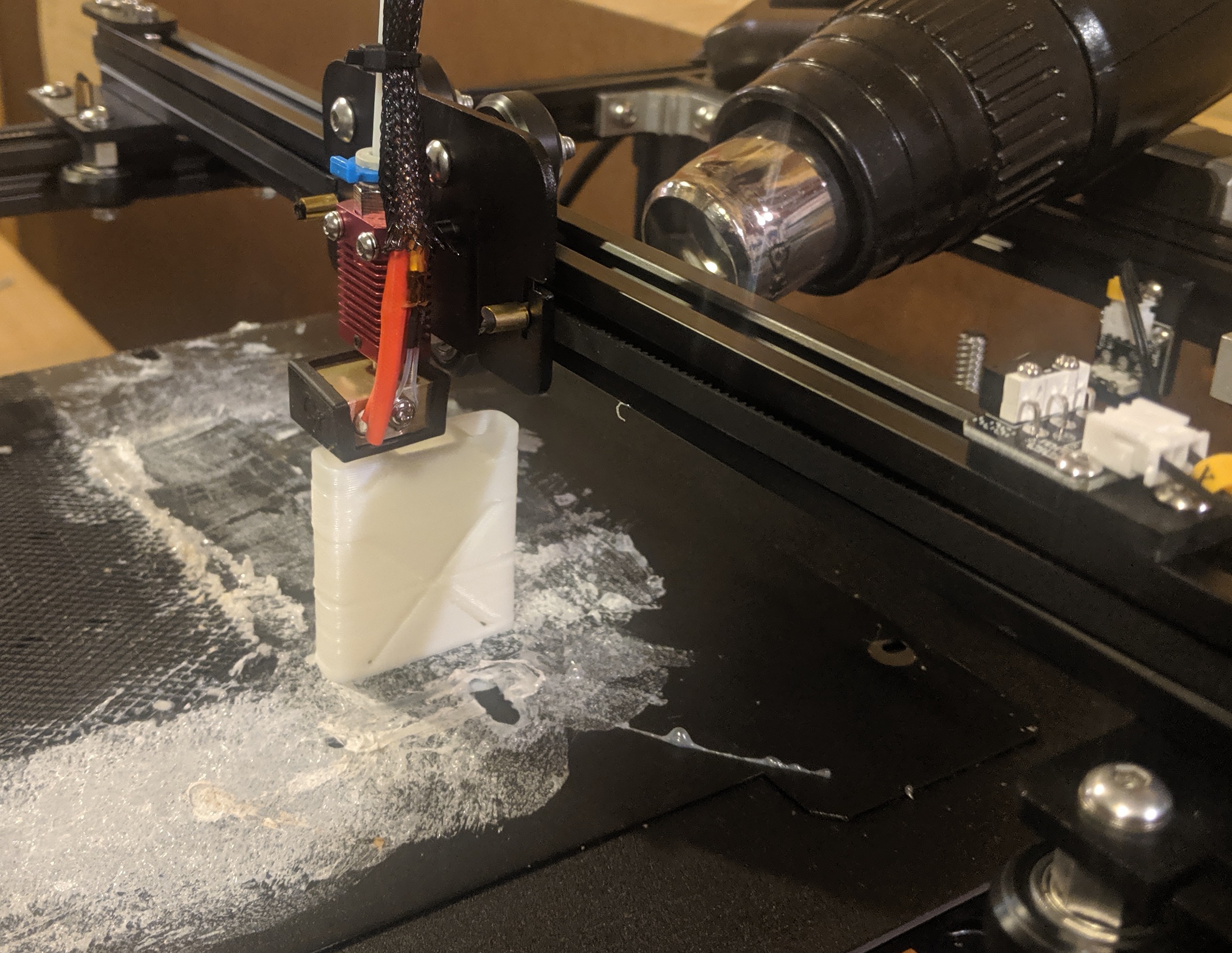
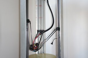
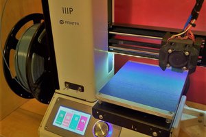
Our build is designed specifically for printing a large enclosure which dimensions are 60in x 48in x 5in and a print goal of sub 3 days while still being strong enough to hold 500lbs of dynamic distributed weight.
ABS was chosen because it is one of the highest thermally conductive plastics and is also engineering grade which is important for high printing speeds with good layer adhesion. The ender5 stock is not a unit which can handle this material at any speed above 40mm/s without warpage. Over 40mm/s you get layer delamination and at 200mm/s the delamination is so bad the layers separate immediately after extrusion due to the high warping of not having a heated enclosure. Please note the stock build surface is not suitable for printing with abs. Source a powder coated build surface or other applicable surfaces for printing abs.
The tests we made to get to that point we're the following:
1. Set part cooling fan speed to zero.
This should be by default in your slicer of choice but if not the reason is abs is very thermally conductive which is why it warps. This helped but the stock hotend fan was also blowing cold are on the part.
2. Get out your tape!
Using the highest quality tape you can source for higher temps seal the bottom of that hotend the best you can. Blue painters tape worked just fine without burning.
3. Increase nozzle diameter
This was done because print speeds of 0.4mm nozzles with big parts is so slow the chances for failed prints only increases and the theory is that thicker extrusions will increase the bond between layers because there is more volume to retain heat.
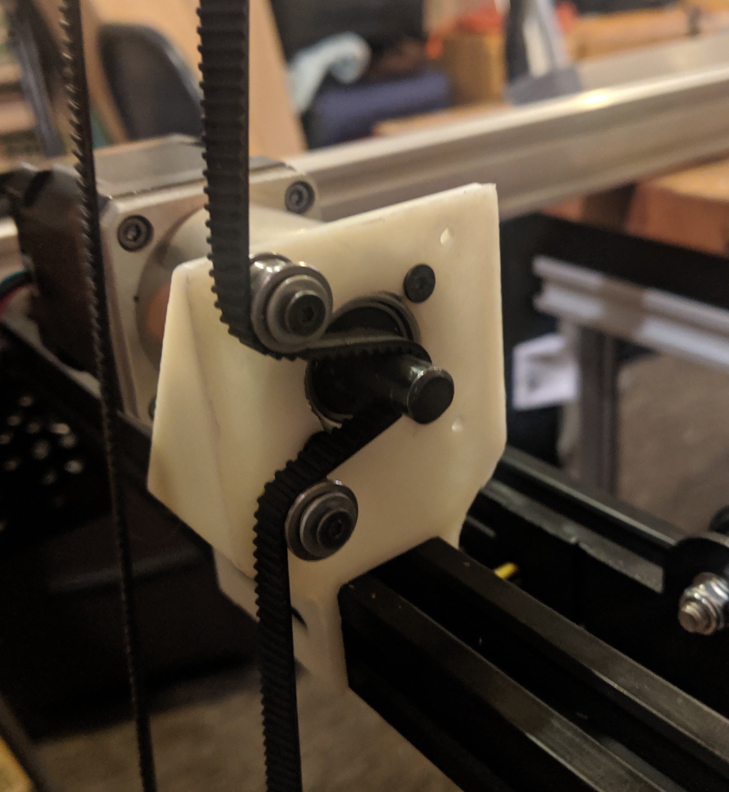
4. Switching the part & hotend fan connections
This allows you to use the fan speed in your slicer to just give enough air accross the heatsink to keep it cool for retractions but lower the amount of leaking airflow over the printing part. This was the chosen path because we aren't interested in changing firmware settings at this point. More on that later!
5. Removal of all fans from the hotend
This enabled much greater chances of allowing heat creep to heat in a longer zone. And give abs more time to heat up for even faster print speeds. YES! This is against all normal printing but a plan for never needing any retractions is part of this build. If you're looking to use this as a guide just leave your heatsink fan as normal. (But upgrade because it is not a good fan shroud design.)
By this point the abs was warping less but still only allowed for slow print speeds .
6. Simulating a heated chamber
This can be done in many ways but the choice to use a hot air gun with adjustable temp was too redneck to pass up! The ace branded heat gun rests perfectly on the y axis motor mount and the extrusion blowing directly in the center where the test piece is placed. Start the temp around the "glass transition" temp. FYI abs has no official temp for this as the material is amorphous and has no exact temp, but 100-110degrees celsius is about the range that is recommended by plastic manufacturers. Due to room temp and the reducing temp as you get farther away from the heat nozzle turning the temp up was needed to reduce warping. Set the temp 20-100 degrees celsius above the glass transition temp depending on your room conditions.
Success! The heated area test worked at preventing abs warpage. On a side note if you are wanting to investigate the use of a hot air gun on open air systems post in the comment section!
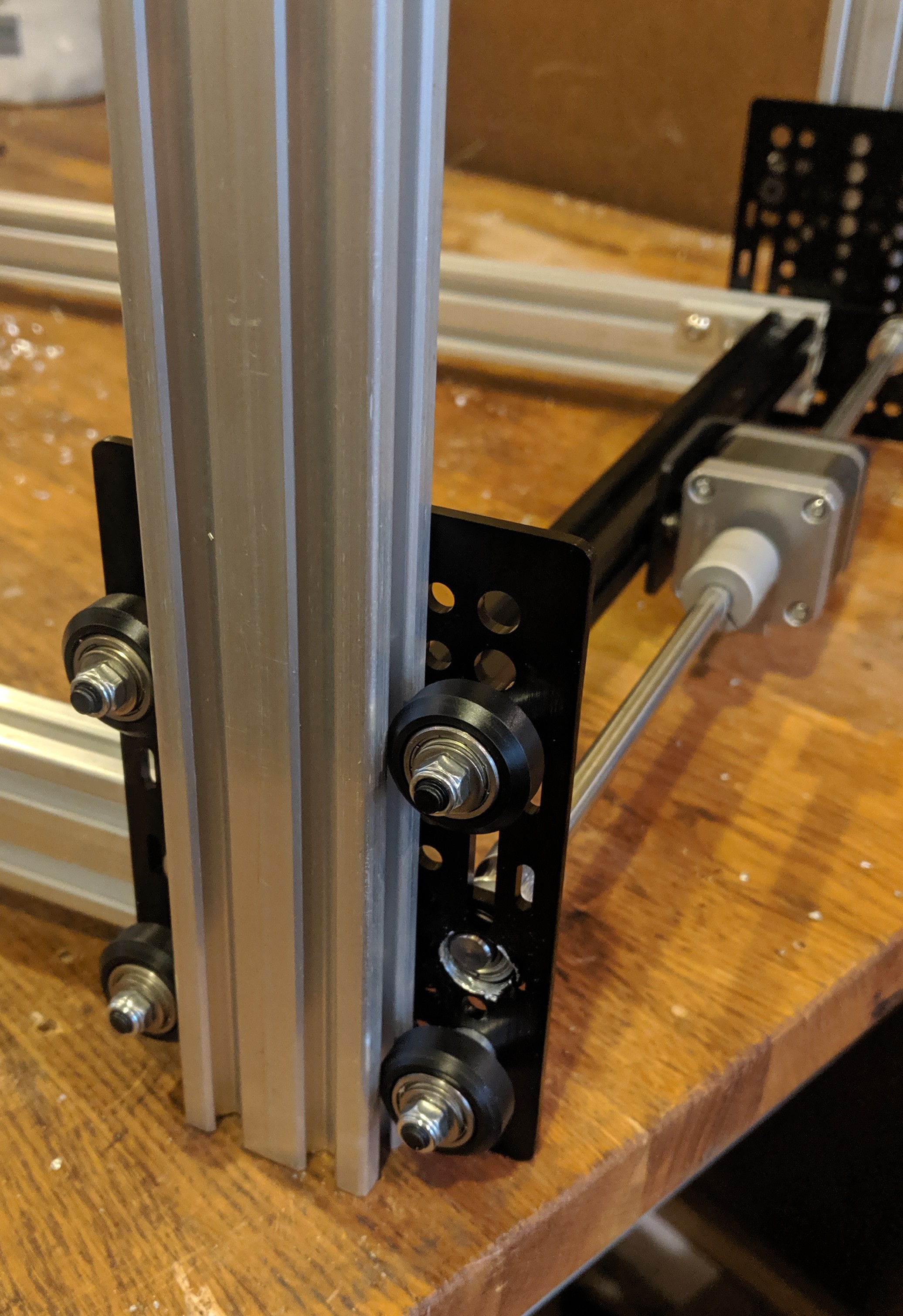
Now that proving a heated enclosure is needed and that abs can be a great material for high speeds the system build can start.

 Dylan Radcliffe
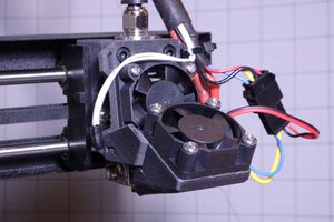
 U.S. Water Rockets
 Marc Schömann