 Jonathan Bumstead
The upright laser harp has been a successful first prototype, but there are a few parts of the design that make it difficult and time consuming to construct. My ultimate goal is to make the upright laser harp into a robust kit. I have the design plans for the first version freely available, but the current build is challenging with some tedious construction stages. Here I will outline my plans for version 2 of the upright laser harp that will make the whole thing easier to construct so it can reach a larger audience. I am also considering selling assembled versions of the upright laser harp.
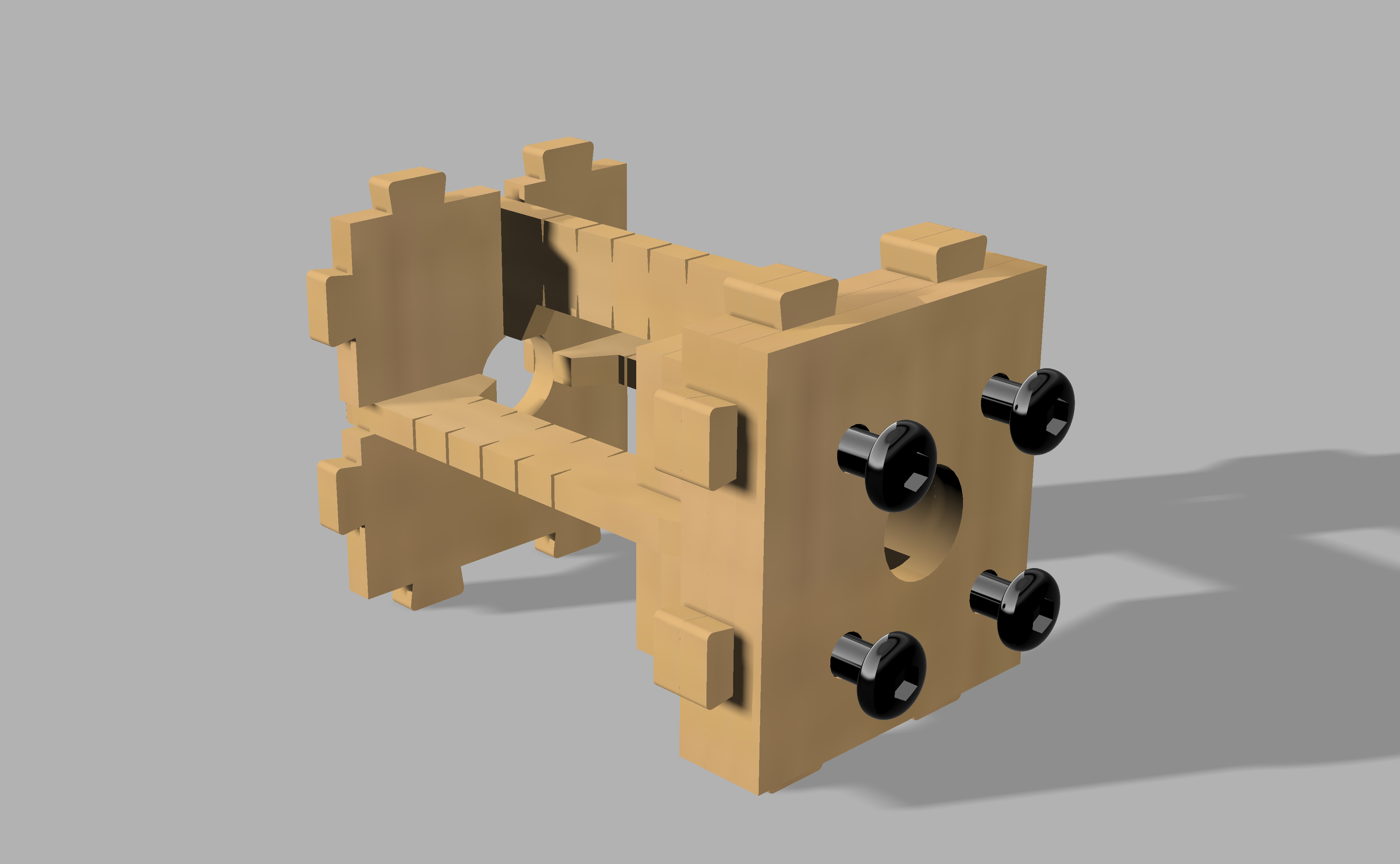
1. Improved kinematic mounts
I spent the most time developing the kinematic mounts for laser beam alignment, but I am still not 100% satisfied with the results. In my first prototype, the lasers are glued into place and there is a "course" adjustment required. In other words, there is variation in how the lasers are positioned in the mount and if the laser is not put in the mount correctly, the fine tuning with the kinematic mount isn't enough to align the beams.
For the next iteration in the laser mount design, I want the lasers to fit firmly in place and make the kinematic mounts flexible enough that they can be used for the full alignment procedure. I also want the kinematic mounts to be more compact.
2. PCB for the photoresistors and laser diodes
In first prototype (V1), the wires from the photoresistors and lasers are fed down through the laser harp. This makes cable management messy and frustrating. My goal for V2 of the upright laser harp is to design PCBs to be positioned at each layer with cable outputs:
- Photodiode output
- Laser output
- 5V
- Gnd
These outputs can be directly connected to the Arduino Mega without the need for a prototype board. With these PCBs, the cables can easily be connected between layers of the laser harp. I also want to use photodiodes instead of photoresistors because of faster response and power consumption.
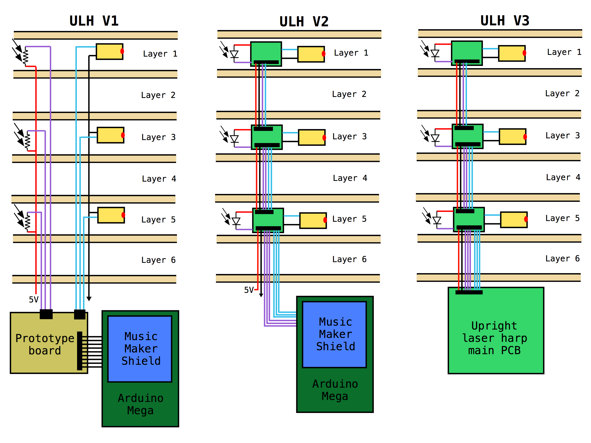
3. PCB for combining Arduino and Music Maker Shield
The Arduino Mega and Music Maker Shield are expensive and I don't need all the pins. In the next stage of prototyping, I want to design a single PCB that combines the ATmega2560 and VS1053 ICs. This custom PCB will be specifically designed for the connectors from the photodiode/laser module PCBs and will cost less than buying the two boards separately.
4. Optimize mechanical design
Finally, I want to improve the overall mechanical design be reducing the requirements for glue, hiding the cabling down through the device, and optimizing the tolerancing. One major issue with the current design is the time required for jamming parts together and glueing because of tight or loose fitting components.
Discussions
Become a Hackaday.io Member
Create an account to leave a comment. Already have an account? Log In.