 yoyojacky
At the first, you just have to mount this hat to your raspberry pi.
and then you need cut off your home electricity and make sure that the power switch is off.
The advantage of relays is that it takes a relatively small amount of power to operate the relay coil, but the relay itself can be used to control motors, heaters, lamps or AC circuits which themselves can draw a lot more electrical power.
The electro-mechanical relay is an output device (actuator) which come in a whole host of shapes, sizes and designs, and have many uses and applications in electronic circuits. But while electrical relays can be used to allow low power electronic or computer type circuits to switch relatively high currents or voltages both “ON” or “OFF”, some form of relay switch circuit is required to control it.
The design and types of relay switching circuits is huge, but many small electronic projects use transistors and MOSFETs as their main switching device as the transistor can provide fast DC switching (ON-OFF) control of the relay coil from a variety of input sources so here is a small collection of some of the more common ways of switching relays.
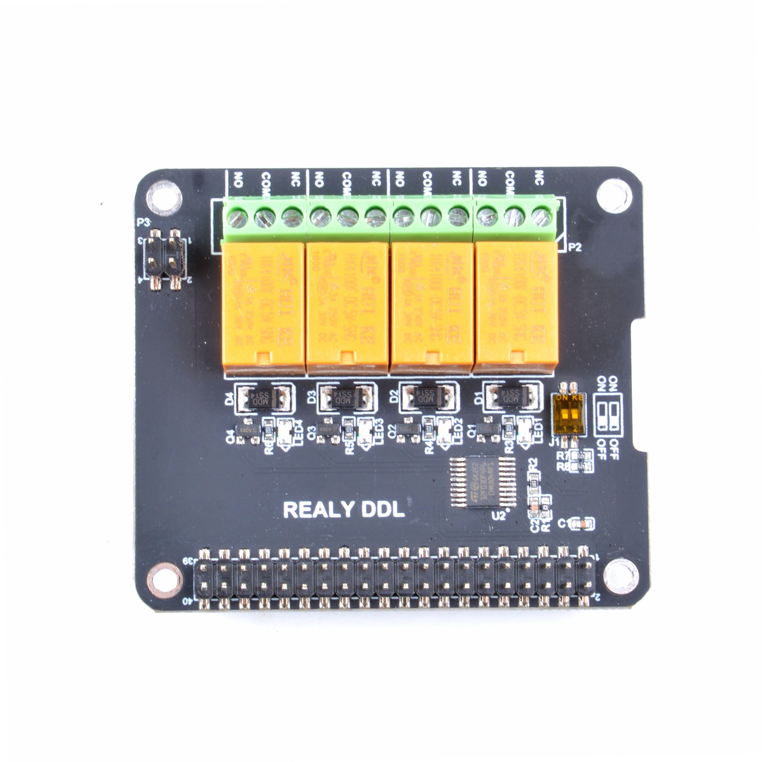
NC means Normal Close
NO means Normal Open
COM means GND or Nagitive pole of your power supply.
it seems like this picture, but it will be easy to connect the relay's controller pin to raspberry pi, all you need to do is connect this part:
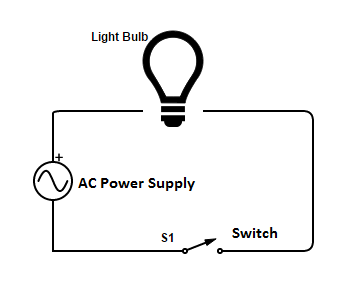
Now, when the light bulb is connected to the main supply, we usually do this by connecting two wires to the bulb. one of the wire is a “Neutral” wire and other one is the “Negative” wire which actually carries the current , also there is a switch added to the whole circuit to control the ON an OFF mechanism. So, when the swith is connected (Or Turned ON) the current flows through bulb and the neutral wire, completing the circuit. This turns the light bulb ON. When the switch is turned of, it breaks the circuit and the light bulb turns OFF. Here’s a small circuit diagram to explain this:
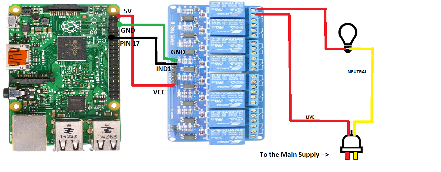
Now, for our experiment, we’ll need to make the “Negative Wire” pass through our relay to break the circuit and control the power flow using relay’s switching. So, when the relay will turn ON, it should complete the circuit and the Light bulb should turn ON and vice-versa. Refer to the below diagram for Full circuit.
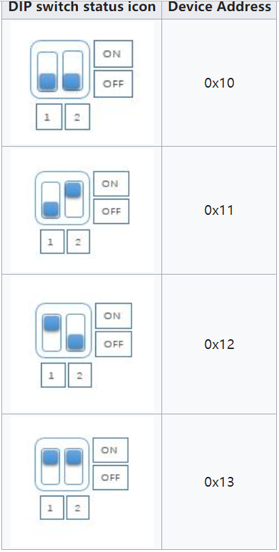
by the way, if you have mounted 4 layers of this relay hat board, you may need to change the register address by modify the DIP switch as following picture.
and then, the hardware part is ok.
next step is to using the command line or write a program to drive it .
Run sudo raspi-config and follow the prompts to install i2c support for the ARM core and linux kernel Go to Interfacing Options

then I2C

Enable!

Done!

Direct control without programming
- Turn on channel No.1 relay
i2cset -y 1 0x10 0x01 0xFF
- Turn off channel No.1 relay
i2cset -y 1 0x10 0x01 0x00
- Turn on channel No.2 relay
i2cset -y 1 0x10 0x02 0xFF
- Turn off channel No.2 relay
i2cset -y 1 0x10 0x02 0x00
- Turn on channel No.3 relay
i2cset -y 1 0x10 0x03 0xFF
- Turn off channel No.3 relay
i2cset -y 1 0x10 0x03 0x00
- Turn on channel No.4 relay
i2cset -y 1 0x10 0x04 0xFF
- Turn off channel No.4 relay
i2cset -y 1 0x10 0x04 0x00
Program in Language C(Raspberry Pi)
Create source code and name it "relay.c"
#include <stdio.h>
#include <wiringPi.h>
#include <wiringPiI2C.h>

#define DEVCIE_ADDR  0x10
#define RELAY1  0x01
#define RELAY2  0x02
#define RELAY3  0x03
#define RELAY4  0x04
#define ON      0xFF
#define OFF     0x00

int main(void){    printf("Turn on Relays in C\n");    int fd;    int i = 0;    fd = wiringPiI2CSetup(DEVICE_ADDR);    for(;;){       for (i=1; i<=4; i++){          printf("turn on relay No.$d", i);          wiringPiI2CWriteReg8(fd, i, ON);          sleep(200);          printf("turn off relay No.$d", i);          wiringPiI2CWriteReg8(fd, i, OFF);          sleep(200);       }    }    return 0;
}
Compile!
gcc relay.c -lwiringPi -o relay
Exec It!
./relay
Program in Python(Raspberry Pi)
The following code is recommended to be executed using Python 3 and install the smbus library:
import time as t
import smbus
import sys

DEVICE_BUS = 1
DEVICE_ADDR = 0x10
bus = smbus.SMBus(DEVICE_BUS)

while True:
    try:
        for i in range(1,5):
            bus.write_byte_data(DEVICE_ADDR, i, 0xFF)
            t.sleep(1)
            bus.write_byte_data(DEVICE_ADDR, i, 0x00)
            t.sleep(1)
     except KeyboardInterrupt as e:
        print("Quit the Loop")
        sys.exit()
Program in Java(Raspberry Pi)[edit]
Create a new file named: I2CRelay.java and paste following code:
import java.io.IOException;
import java.util.Arrays;

import com.pi4j.io.i2c.I2CBus;
import com.pi4j.io.i2c.I2CDevice;
import com.pi4j.io.i2c.I2CFactory;
import com.pi4j.io.i2c.I2CFactory.UnsupportedBusNumberException;
import com.pi4j.platform.PlatformAlreadyAssignedException;
import com.pi4j.util.Console;

public class I2CRelay {
    // relay's register address.    public static final int DOCKER_PI_RELAY_ADDR = 0x10;     // channel of relay.    public static final byte DOCKER_PI_RELAY_1 = (byte)0x01;    public static final byte DOCKER_PI_RELAY_2 = (byte)0x02;    public static final byte DOCKER_PI_RELAY_3 = (byte)0x03;    public static final byte DOCKER_PI_RELAY_4 = (byte)0x04;
    // Relay status    public static final byte DOCKER_PI_RELAY_ON = (byte)0xFF;    public static final byte DOCKER_PI_RELAY_OFF = (byte)0x00;
    public static void main(String[] args) throws InterruptedException, PlatformAlreadyAssignedException, IOException, UnsupportedBusNumberException {
        final Console console = new Console();
        I2CBus i2c = I2CFactory.getInstance(I2CBus.BUS_1);        I2CDevice device = i2c.getDevice(DOCKER_PI_RELAY_ADDR);
        console.println("Turn on Relay!");        device.write(DOCKER_PI_RELAY_1, DOCKER_PI_RELAY_ON);
        Thread.sleep(500);
        console.println("Turn off Relay!");        device.write(DOCKER_PI_RELAY_1, DOCKER_PI_RELAY_OFF);    }
}
- Compile it and running:
javac I2CRelay.java -classpath .:classes:/opt/pi4j/lib/'*'
sudo java -classpath .:classes:/opt/pi4j/lib/'*' I2CRelay
Git Repository
You can also clone the repository from github:
sudo apt-get update sudo apt-get -y install git
git clone https://github.com/geeekpi/dockerpi
cd dockerpi/
Running Differenet program with different way.