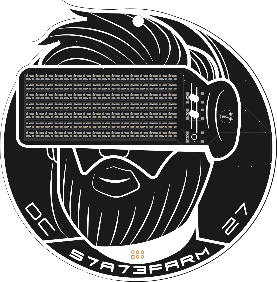
 s7a73farm
What does it do?
The badge is audio reactive so the 23 different LED modes move and react to the music.
Components
- ESP32 -WROOM
- 112 x SK6812-MINI RGB LEDS
- Micro USB with UART USB SERIAL plus USB Charging
- 1500 MaH LiPo Battery
Lessons Learned, Making the Badge
DEF CON 27 was to say the least an amazing experience. I got in to Badgelife at DEF CON 26 to learn more about hardware. I also figured it was a great way to promote my DJ sets during DEF CON. Last year’s badge was a bit of a fiasco. I raised funds on KickStarter, the badge was a very basic design with 15 leds and a few patterns. I had learned so many lessons last year. To read last years write up click here. https://medium.com/@s7a73farm/badgelife-the-good-the-bad-and-the-i-did-not-see-that-coming-c64c081f517
Taking the lessons learned and trying again.
Starting Early:
This year I procrastinated, mostly because you always have time until you don’t. So late April I quickly realized I needed to get going. Last year I decided that LEDs look better when reacting to sound or music. So, I began researching ideas, DEF CON had released the theme for DC27 as retro-futurism utopia.
The Concept:
Through my research I had found some things that inspired me. I found a logo design that inspired me of a woman with VR type goggles. I reached out to the artist, but the last time he had any online presence was mid-2000s. I tried to contact him to commission some work. Even as I write this, I never received a reply. So, I reached out to another artist/designer I knew to create something similar but with me and my beard.

Now that I had art, and a basic concept I reached out to Compukidmike to help me with the engineering. Compumikekid has built multiple badges and is insanely fast with PCB design. We decided to use WS2812 3535 LEDs because they were small enough to fit on the design. For the Audio mic we used the Spark fun break out board design. We chose the ESP32 for the MCU because it had Bluetooth and WIFI. The original concept was the badge would be a soft AP where you could connect and write your own text to scroll across the badge. The BLE would be used to create a party mode if more than 5 badges were within range.
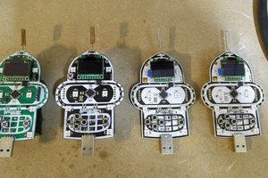
The Prototype:
So, we order the initial prototypes and parts. When they arrived Compukidmike and I start assembling. This is when we hit our first failure. The LED pins for the 3535s are different then the 5050s. They rotate pins in the smaller size.


Our PCB did not account for this. When we tried to solder the LEDS it was a disaster.
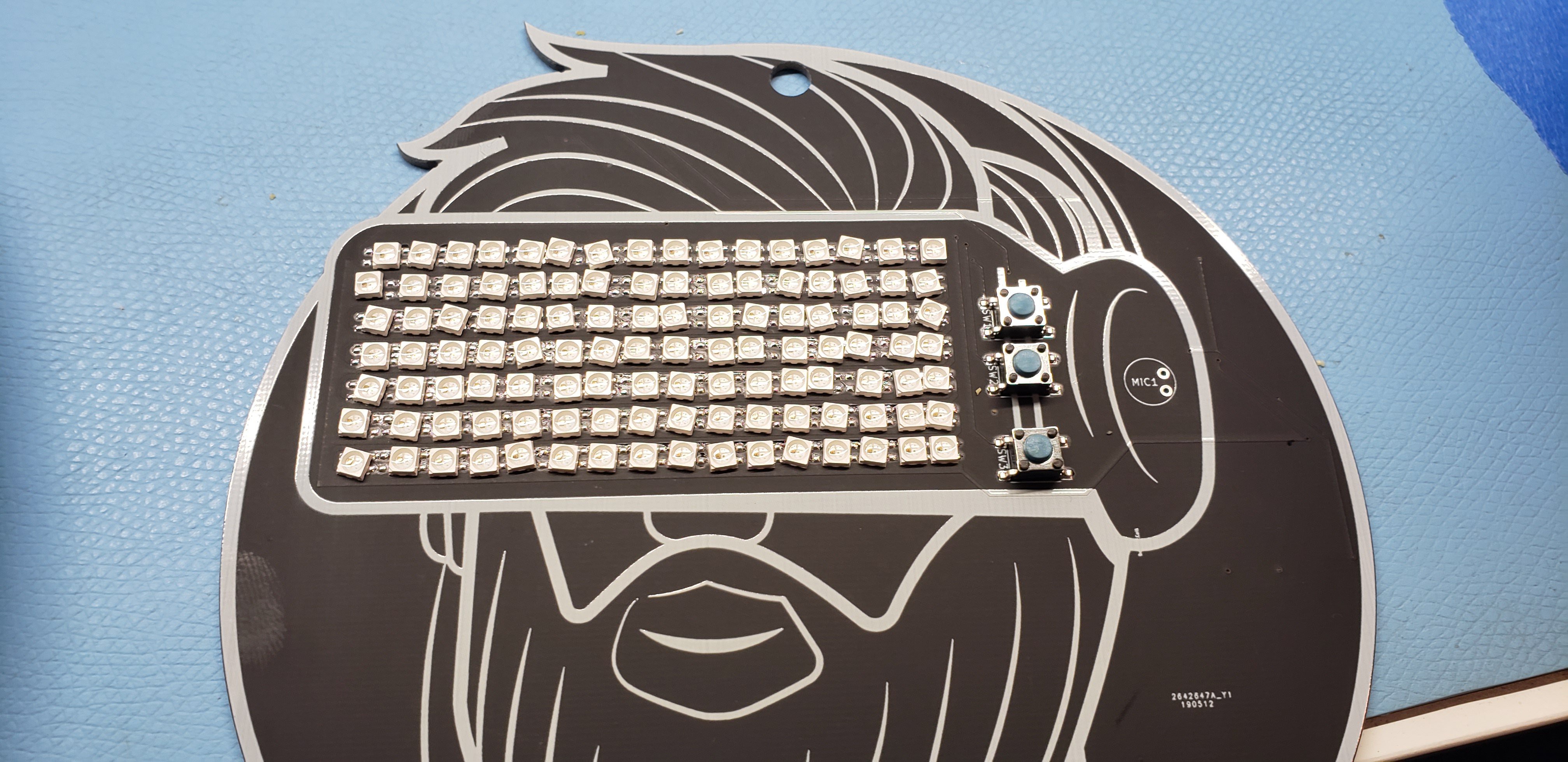
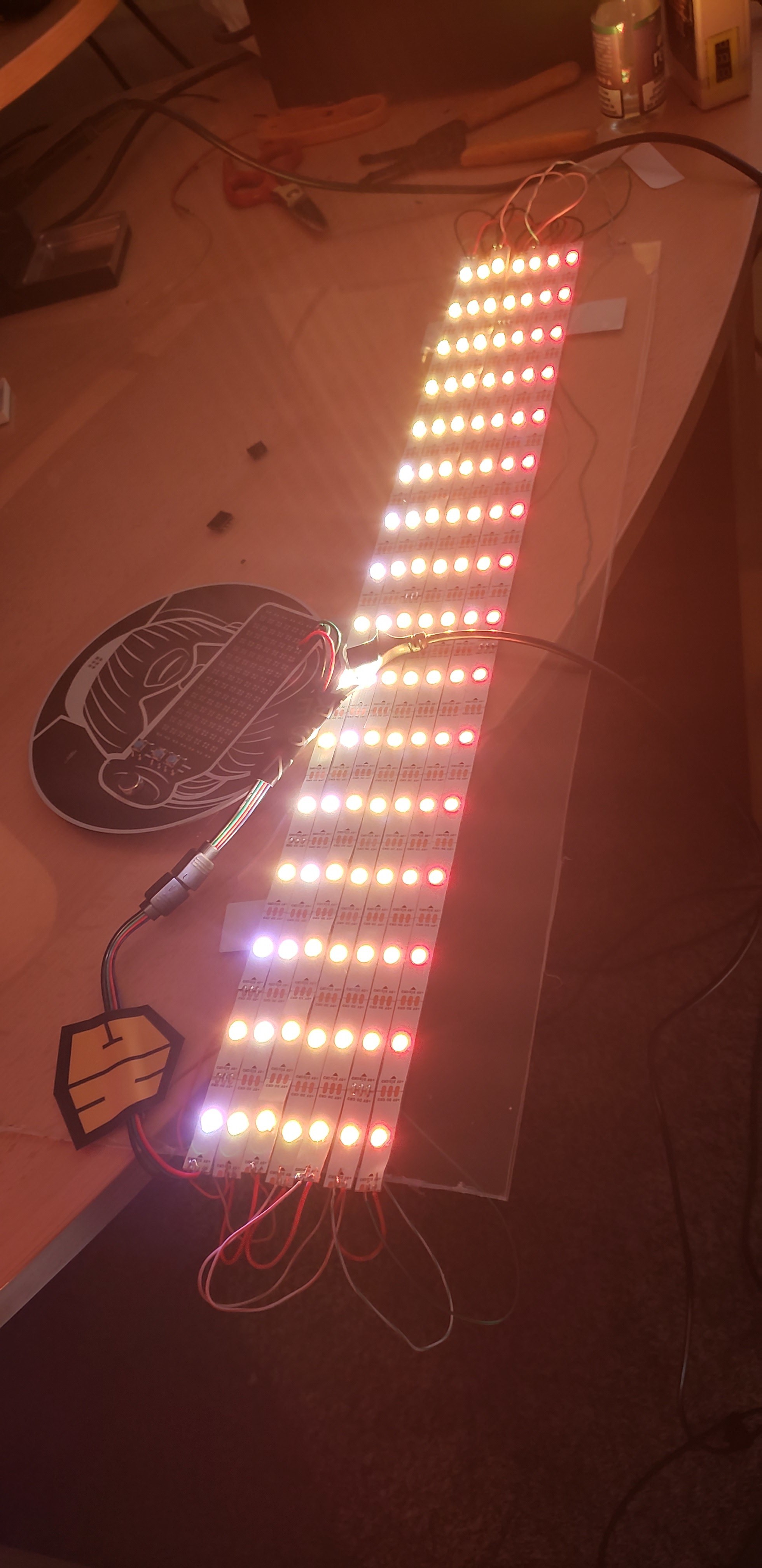
We redesigned the PCB with the correct pads. We assembled the rest of the components minus the LEDs on one prototype, then added an LED strip adapter to the board so I could make a matrix from led strips to begin coding. We validated the mic was reading data and feeding it to the ESP32.
The Production run:
Once we validated it worked (Sort of I will explain). I shopped around for PCB with assembly. I landed on https://www.seeedstudio.com/prototype-pcb-assembly.html Their quoting application was insanely easy to use, and the BOM upload was easy. They provide a template to use, once uploaded their system auto identifies what they have in stock. If they are missing a part, they are pretty quick at contacting you if they can get it. I worked with Seeed and chose to sign up to their Badgelife Sponsorship. They provided a discount for a review of the service. This was the first time I had used a manufacturer to assemble the badges. There were a few mistakes that I made. 1st was I did not check on availability of the WS2812 Minis. Had I started sooner I would have been able to produce a higher quantity; each badge has 112 LEDs so at 100 badges that was 112K LEDs. 2nd was a mistake on the BOM for the MicroUSB part, I listed the wrong part number. 3rd During programming of prototype I realized I had the MIC pins...
Read more »
 awkward intelligence
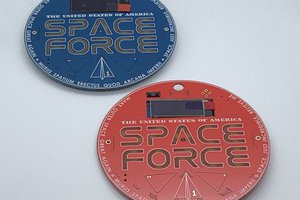
 Zapp
Zapp
 Benchoff
cool silkscreen