 Simon Trendel
The following image shows an overview of the components used in v0.7:
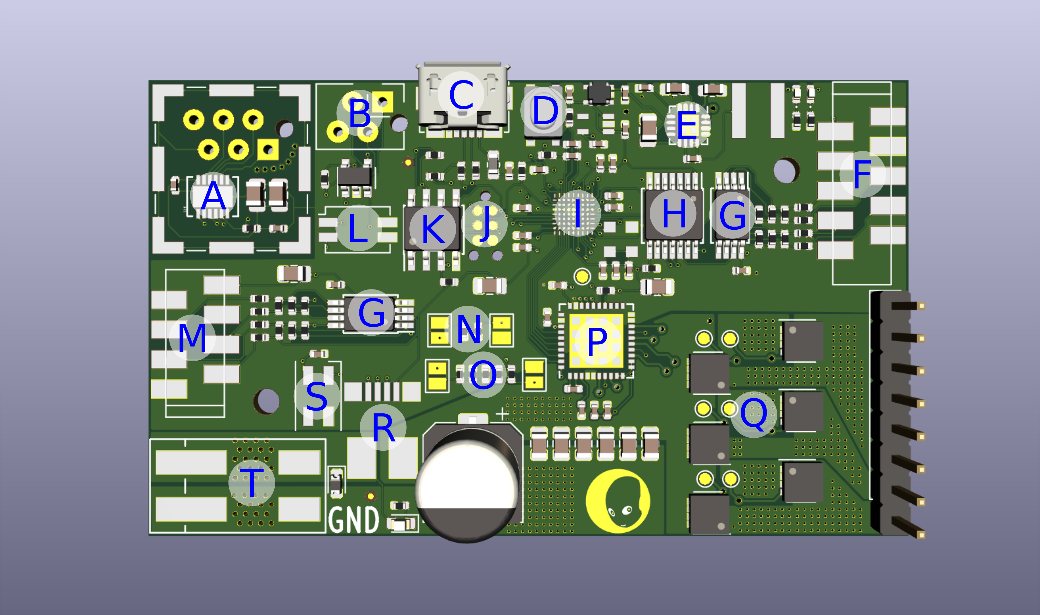
- A: RS486 differential transceiver
- B: I2C connector connected to the EEPROM
- C: micro-USB port for flashing
- D: reset button
- E: 5V DC-DC converter
- F: Maxon position encoder micro-match connector
- G: Differential converter chip for encoder
- H: Level-shifter 5V->3.3V
- I: ice40 fpga
- J: tag-connect SPI port to flash
- K: flash
- L: dip-switch for toggling eeprom read-only and RS485 termination resistor
- M: Second position encoder
- N: drv8323 mode control
- O: drv8323 gate current control
- P: drv8323 chip
- Q: three NPN-mosfet half bridges
- R: TLI4970 current sensor
- S: neopixel
- T: Power connector
The following section gives some details about the motor control code.
We are using the Texas Instrument drv8323hrta chip in independent mode. This means we have full control over the mosfet gates. Commuting the phases seemed trivial at first, but as it turns out, you need to know the specs of your mosfets really well in order to do this right. The key word here is dead time insertion. It essentially refers to the mosfets not being ideal switches and not turning on or off instantaneously, but with a certain delay. When we commute the phases, we have to be sure the opposing mosfets are closed, otherwise you can easily burn your mosfets by shoot through gate states. One common way is to use dead time insertion. The exact timing can be calculated from the specs of our mosfets, and I will make a mental note now to do that later. For now we are just using an arbitrary large enough dead time. For our application the motor spins quite slow and the big dead time will be really only noticeable at high motor speeds. Here is the code that handles our bldc commutation:
always @(posedge clk16MHz) begin: BLDC_COMMUTATION
   commutation_state_prev <= commutation_state;

   if(commutation_state!=commutation_state_prev)begin
     dti <= 1;
     dti_counter <= 1024;
   end

   if(hall1 && ~hall2 && hall3)begin
     commutation_state <= A;
   end
   if(hall1 && ~hall2 && ~hall3)begin
     commutation_state <= B;
   end
   if(hall1 && hall2 && ~hall3)begin
     commutation_state <= C;
   end
   if(~hall1 && hall2 && ~hall3)begin
     commutation_state <= D;
   end
   if(~hall1 && hall2 && hall3)begin
     commutation_state <= E;
   end
   if(~hall1 && ~hall2 && hall3)begin
     commutation_state <= F;
   end

   if(dti) begin
     if(dti_counter==0)begin
       dti <= 0;
     end else begin
       dti_counter <= dti_counter -1;
       GHA <= 0; GLA <= 0; GHB <= 0; GLB <= 0; GHC <= 0; GLC <= 0;
     end
   end else begin
    if(dir)begin
      case(commutation_state)
         B: begin
           GHA <= 1; GLA <= 0; GHB <= 0; GLB <= 1; GHC <= 0; GLC <= 0;
         end
         C: begin
           GHA <= 1; GLA <= 0; GHB <= 0; GLB <= 0; GHC <= 0; GLC <= 1;
         end
         D: begin
           GHA <= 0; GLA <= 0; GHB <= 1; GLB <= 0; GHC <= 0; GLC <= 1;
         end
         E: begin
           GHA <= 0; GLA <= 1; GHB <= 1; GLB <= 0; GHC <= 0; GLC <= 0;
         end
         F: begin
           GHA <= 0; GLA <= 1; GHB <= 0; GLB <= 0; GHC <= 1; GLC <= 0;
         end
         A: begin
           GHA <= 0; GLA <= 0; GHB <= 0; GLB <= 1; GHC <= 1; GLC <= 0;
         end
       endcase
     end else begin
      case(commutation_state)
        B: begin
          GHA <= 0; GLA <= 1; GHB <= 1; GLB <= 0; GHC <= 0; GLC <= 0;
        end
        C: begin
          GHA <= 0; GLA <= 1; GHB <= 0; GLB <= 0; GHC <= 1; GLC <= 0;
        end
        D: begin
          GHA <= 0; GLA <= 0; GHB <= 0; GLB <= 1; GHC <= 1; GLC <= 0;
        end
        E: begin
          GHA <= 1; GLA <= 0; GHB <= 0; GLB <= 1; GHC <= 0; GLC <= 0;
        end
        F: begin
          GHA <= 1; GLA <= 0; GHB <= 0; GLB <= 0; GHC <= 0; GLC <= 1;
        end
        A: begin
          GHA <= 0; GLA <= 0; GHB <= 1; GLB <= 0; GHC <= 0; GLC <= 1;
        end
      endcase
     end
   end
 end
The hall sensor inputs control the commutation state we are in. Depending on the direction we want to turn the motor, the respective gates are opened. Whenever the commutation state changes, dead time is inserted (dti).
We are using a 20kHz PWM signal for the gates. The PWM is calculated in the following way:
localparam CLK_FREQ   = 16_000_000;
localparam PWM_FREQ   = 20_000;

reg signed [23:0] pwm_counter;

always @(posedge clk, posedge reset) begin: PWM
  if(reset) begin
    pwm_counter <= 0;
  end else begin
    pwm_counter <= pwm_counter+1;
    if(pwm_counter>=(CLK_FREQ/PWM_FREQ)) begin
      pwm_counter <= 0;
    end
    if(pwm_counter<duty)begin
      pwm_out <= 1;
    end else begin
      pwm_out <= 0;
    end
  end
end
This gives us 16_000_000/20_000 = 800 range for our PI controller:
localparam  CLOCK_FREQ = 16_000_000;
localparam  CONTROL_FREQ = 1000;

reg signed [23:0] result;
assign duty = result;
reg control_update;
integer counter;

always @ ( posedge CLK ) begin
  counter <= counter+1;
  control_update <= 0;
  if(counter>(CLOCK_FREQ/CONTROL_FREQ))begin
    counter <= 0;
    control_update <= 1;
  end
end

always @ ( posedge CLK , posedge reset) begin: PID_CONTROLLER
  reg signed [23:0] err;
  reg signed [23:0] err_prev;
  reg signed [23:0] integral;
  if(reset)begin
    err = 0;
    err_prev <= 0;
    result = 0;
    integral = 0;
  end else begin
    if(control_update)begin
      err = (setpoint-state);
      integral = integral+err;
      if(integral>IntegralLimit) begin
        integral = IntegralLimit;
      end else if(integral<-IntegralLimit) begin
        integral = -IntegralLimit;
      end
      result = Kp*err + Ki*integral;
      if((result>deadband) || (result < -deadband))begin
        if(result>PWMLimit)begin
          result = PWMLimit;
        end else if(result<-PWMLimit)begin
          result = -PWMLimit;
        end
      end else begin
        result = 0;
      end
    end
  end
end
We chose the control frequency to be 1000, which seems reasonable for our motor.
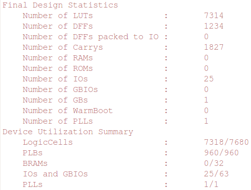
Next lets talk about communication. We augmented the icebus protocol with a few more fields and modified the automatic setpoint and control mode update cycles on the de10 side. We reduced the size of all 32-bit signed integers to 24-bit signed, which reduces the LEs consumption a lot. This was necessary because we started to hit the limit on whats available on our precious iCE40LP8k.
The message types are summarized here:
- COMMAND:
header 0xD0D0D0D0 (4 byte)
motorID (1 byte)
setpoint (3 byte)
neopxl_color (3 byte)
crc16 (2 byte)
- CONTROL_MODE:
header 0xBAADAA55 (4 byte)
motorID (1 byte)
control mode (1 byte)
Kp (2 byte)
Ki (2 byte)
Kd (2 byte)
PWMLimit (3 byte)
IntegralLimit (3 byte)
deadband (3 byte)
setpoint (3 byte)
current_limit (2 byte)
crc16 (2 byte)
- STATUS_REQUEST:
header 0x1CE1CEBB (4 byte)
motorID (1 byte)
crc16 (2 byte)
- STATUS_RESPONSE:
header 0x1CEB00DA (4 byte)
motorID (1 byte)
encoder0_position (3 byte)
encoder1_position (3 byte)
setpoint (3 byte)
duty (3 byte)
displacment (3 byte)
current (2 byte)
neopxl_color (3 byte)
crc16 (2 byte)
The icebus protocol was augmented by a couple of fields. The following image shows a logic analyser capture of the status_request/response mechanism:

The host initiates a status request with the corresponding header 0x1CE1CEBB followed by the motor_id (in this case 0x80) and the crc16 checksum. The motorboard with this motor_id then replies with the status response message. In case either the control_mode or setpoint does not match, an automatic command message is send by the host:
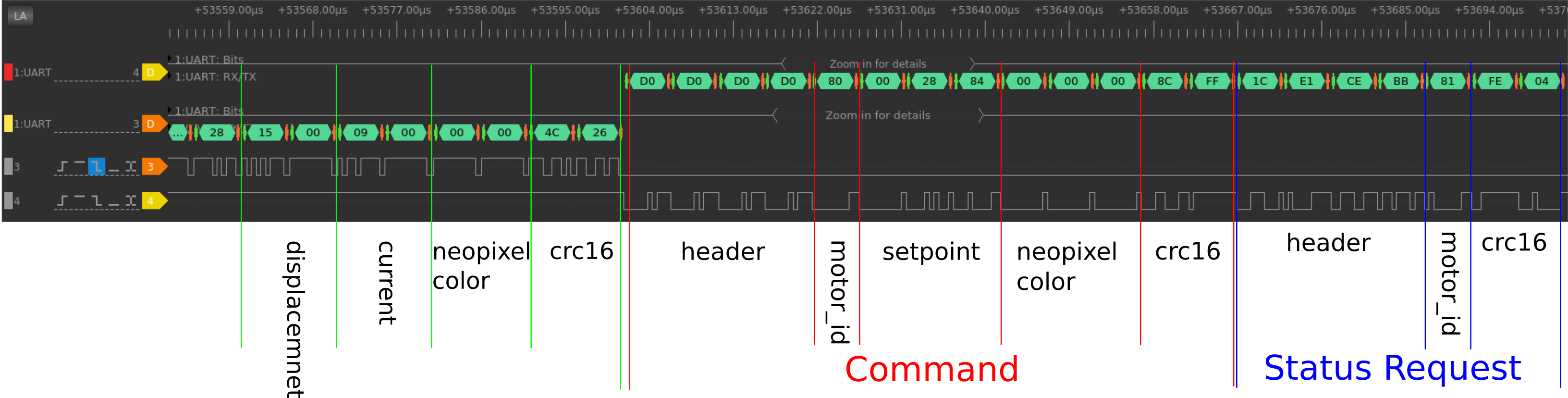
The baud rate in the example above was set to 2MHz, which allows control frequencies of 500 Hz for 10 motors on a icebus.
If you want to talk to multiple iceboards, each one needs a unique 8bit ID. This ID can be conveniently stored on the 16kB eeprom on the iceboard. The ID is read when the board boots via i2c. The eeprom can be written with an arduino board using this sketch. Before, the ID was hard-coded into each fpga build. The arduino sketch also allows you to write the desired baudrate into the eeprom. In the future the eeprom can be used to store iceboard specific stuff, like eg parameters of a calibration of one of our muscle units.
Last but not least, we implemented a spi module to read out our TLI4970 current sensor. The current can now be limited too, for example to 1 amp and the iceboard will automatically throttle the pwm if this value is exceeded. This can be extremely useful if your motor only supports a certain continuous current, and or you cannot cool your motor enough under certain loads. In any case this lets me sleep better because burning one of our maxon motors really hurts.
Now before I go, I should mention the fuck-ups on this version. There are three:
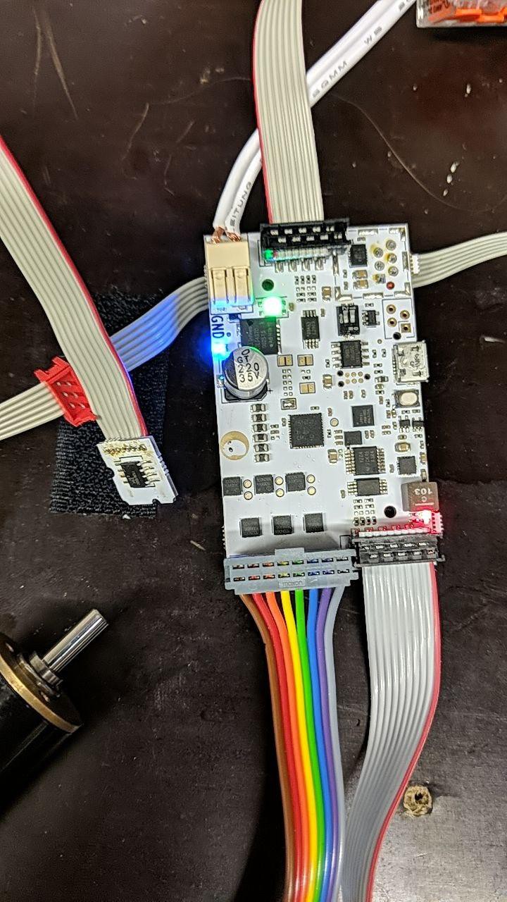
- wrong components in the BOM. The 3.3V DC-DC converter, the DIP switch and two or three caps had the wrong footprint.
- chip enable pin of the 5V->3.3V logic level chip was pulled low instead of high. Fortunately the 3.3V clock supply pin was very close. If you zoom in on one of the boards you can see the 0402 pull-up connected to the clk pin.
![]()
- In the schematics a few of the resistors for the two encoders were
marked as optional for impedance matching, but they made it into the BOM and got assembled. We actually did not check if those would be fine, but the 10k pull-ups on those lines were definitely too weak and had to be replaced manually by 1k
In the next log we will show the results of excessive endurance testing of our v0.7 boards.
Discussions
Become a Hackaday.io Member
Create an account to leave a comment. Already have an account? Log In.