 Simon Trendel
For FOC we need to measure the current flowing in our motor windings. The drv8323 chip supports this by adding shunt resistors on the low side mosfets as can be seen in the datasheet:
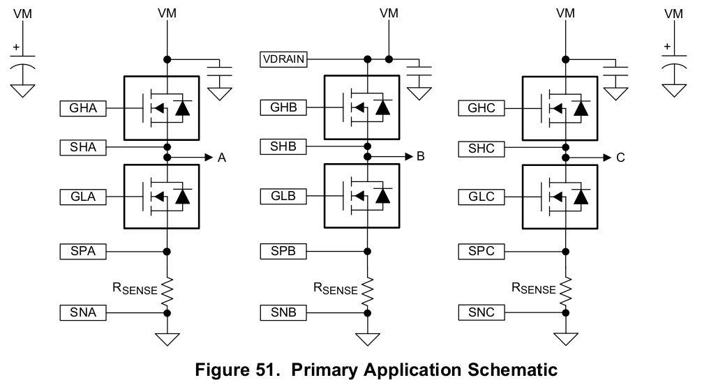
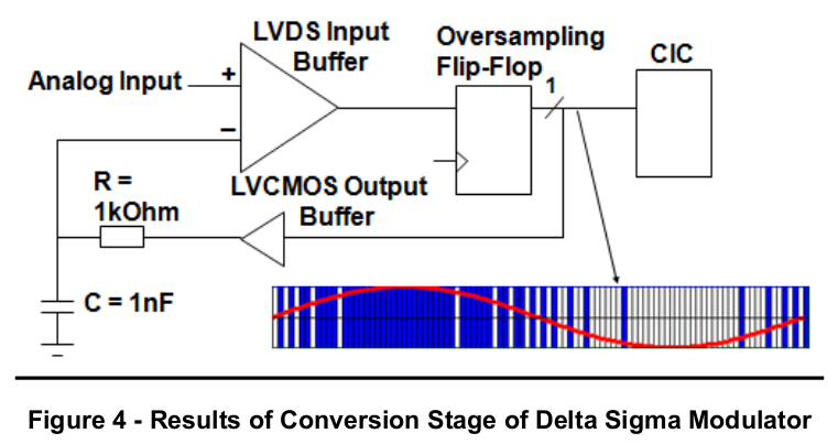
The chip internally amplifies the signals and provides an analog representation on the SOA, SOB, SOC pins. This means, we can get the current more or less for free by adding the shunt resistors. The only downside is, we need an adc. The iCE40lp8k doesn't have an adc, but lattice provided a beautiful paper, explaining how to make your own, using the lvds pins of the fpga. All you need for this, is a simple RC network and in addition to one lvds pair, one more pin for tracking the voltage:
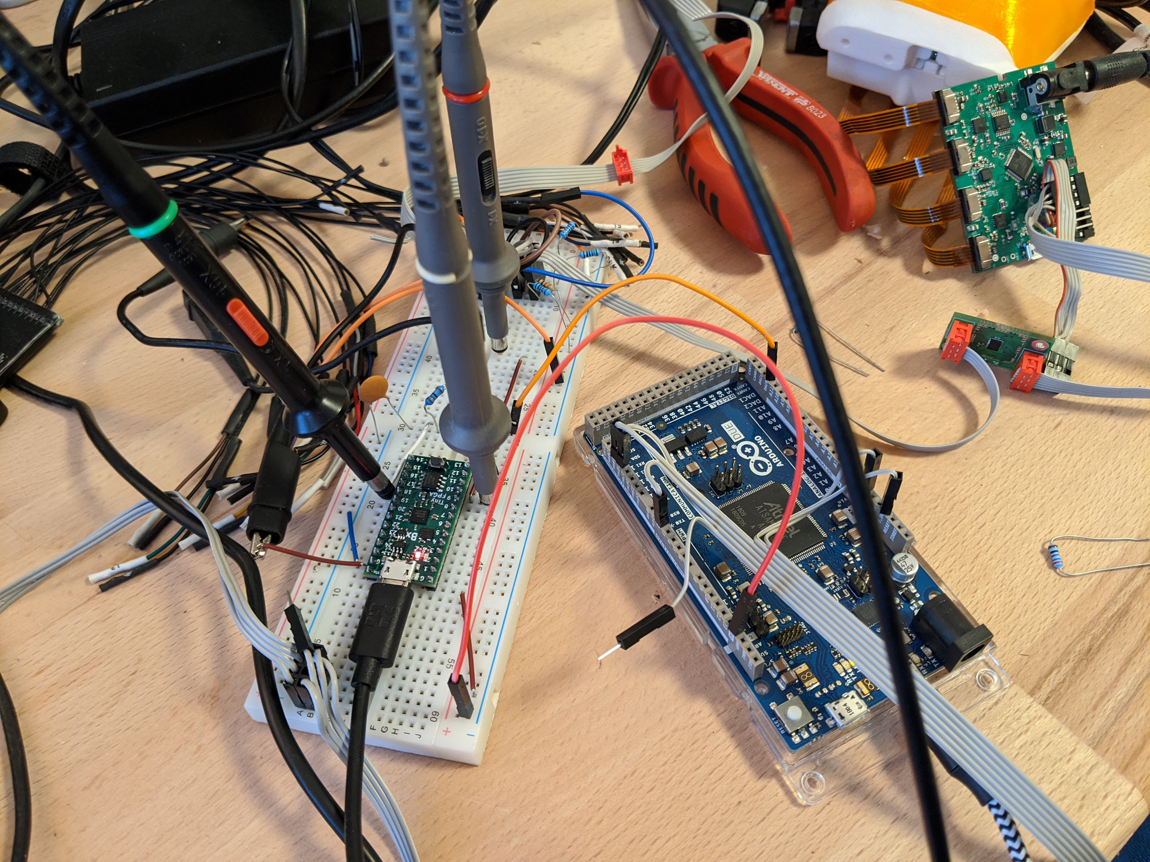
To test our adc we are using an arduino due and its' dac to produce a voltage waveform. You can find the sketch here. The code running on a Tinyfpga-BX is very simple, you can find it here. We didn't have the cap and resistor values as recommended in the datasheet. In this setup we are using 1.8k and 220nF:
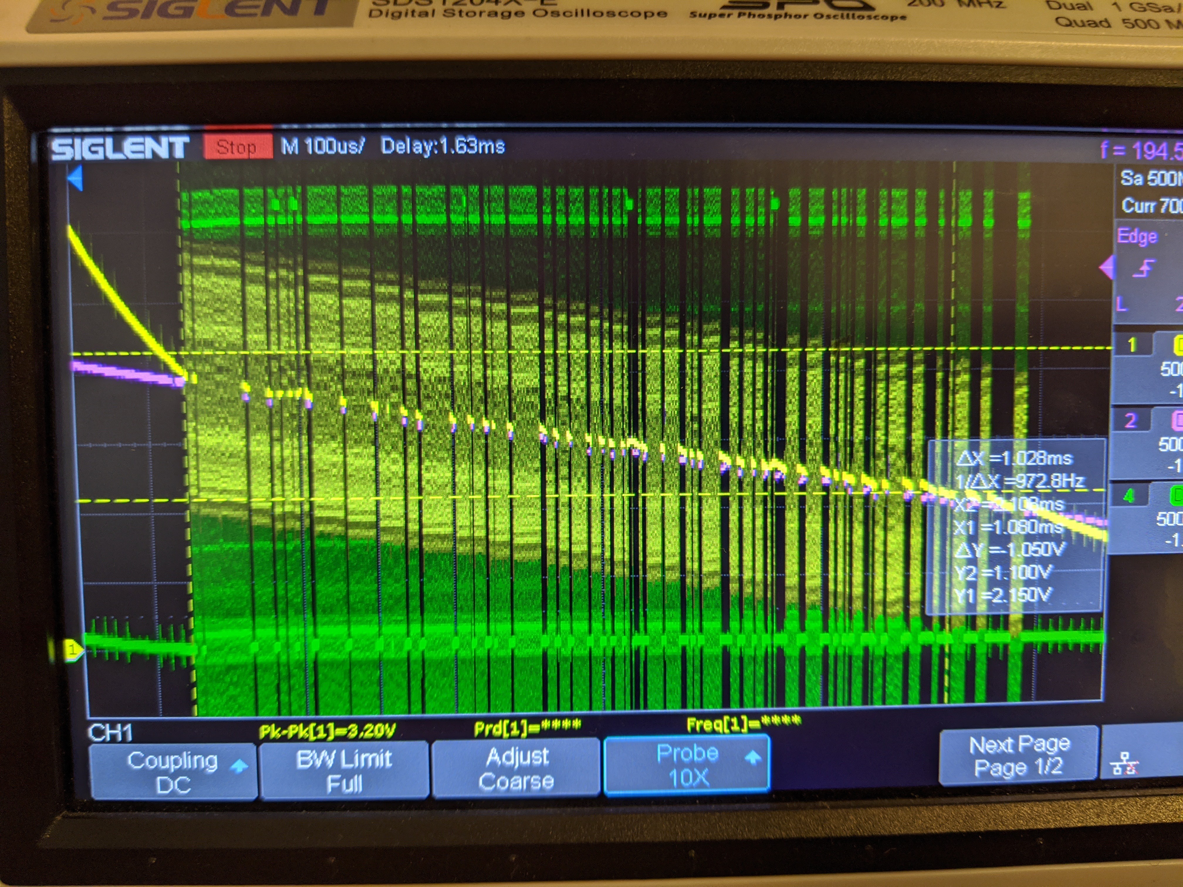
The fpga is able to track the voltage quite well, within a certain voltage range:
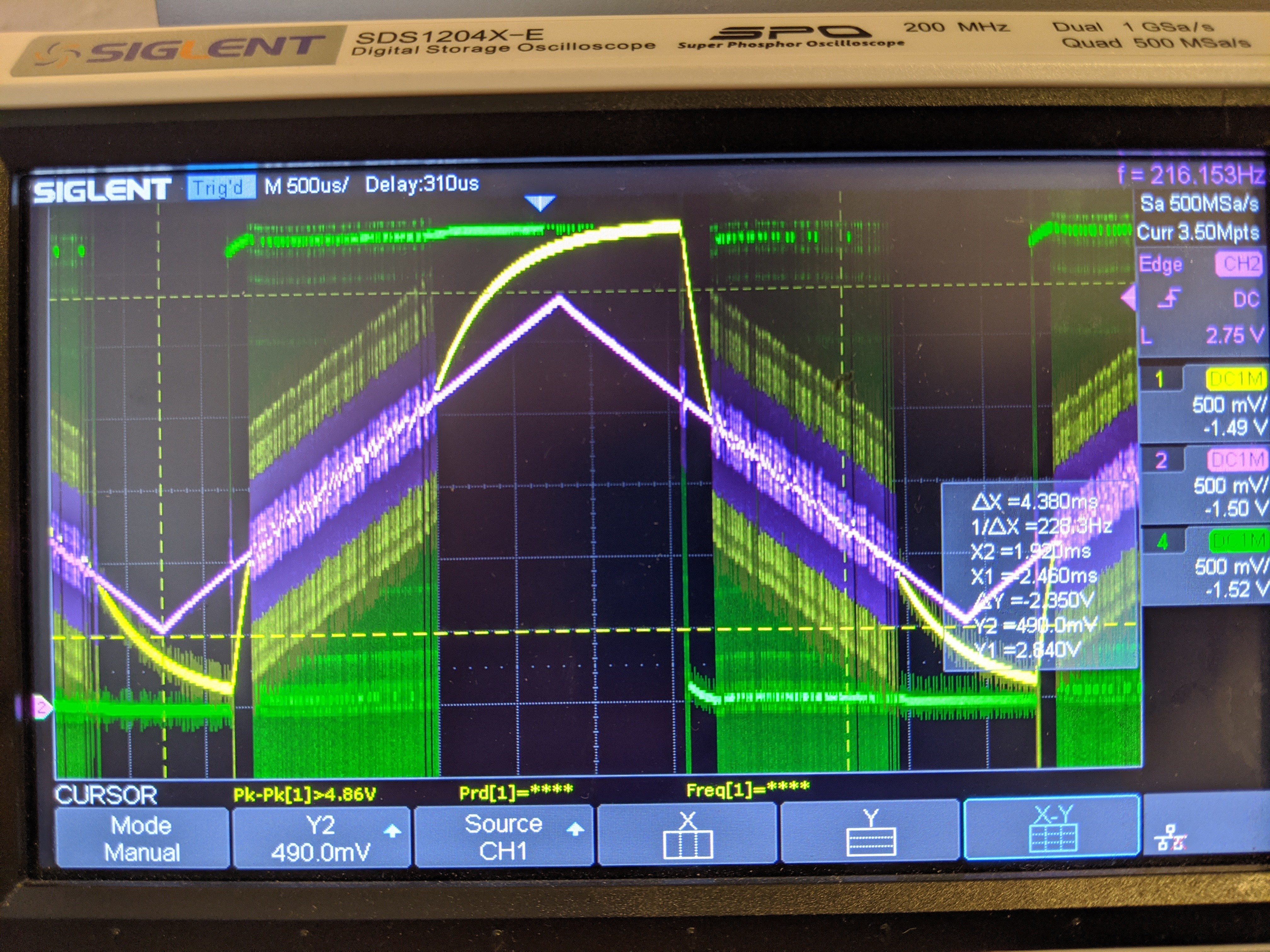
In the picture above, violet is the target voltage coming from the arduino due. It's just ramping up and down between 500mV and 2.8V at around 200Hz. Yellow is the output of the RC network and green is the LVCMOS input into the RC network. As you can see, the yellow line is able to track the violet target voltage quite well, between 1.1-2.1V:

And I think this is related to the LVDS specs, as taken from the ice40 family handbook:
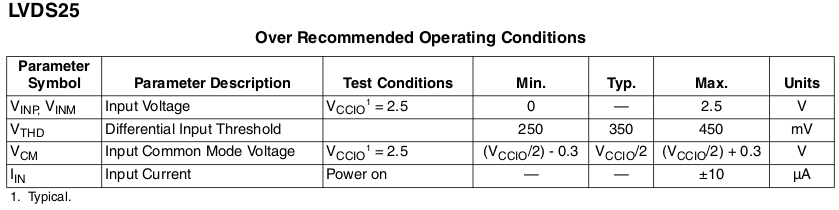
So the max voltage for the lvds input is 2.5V and there is also a differential input threshold given, typically 350mV. So this means that the lvds pins will detect a difference between each other only above 350mV. This might be an explanation why the fpga looses tracking in these areas. And also why the tracking voltage oscillates so much around the target voltage. The tracking voltage overshoots within the differential input threshold voltage band.
To get a digital value, representing the voltage level, the green PDM (pulse density modulation) signal needs to be converted. Lattice recommends a CIC filter in their paper and I remember dealing with a similar conversion problem when working with MEMS-microphones. In the following picture you can see, how the green PDM signal density goes down with the voltage. This change in pulse density encodes our voltage level.
 Before we go down the rabbit hole of digital filter design (eg following a guide like this)...The PDM signal can be converted simply by adding the PDM signal within a certain window. We chose a 256 clock tick window for the integration, because this allows the generated 8bit value to be conveniently send via uart. The arduino due was used to forward the uart data via ROS and was then plotted in rqt_plot:
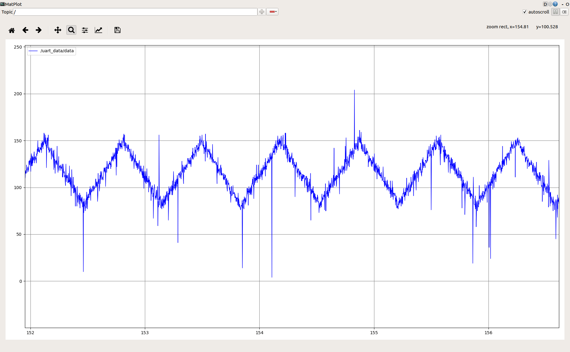
As can be seen in the plot above, the integrated value represents the voltage level. It is quite noisy and only valid within the valid voltage range, but not so bad for starters.
Discussions
Become a Hackaday.io Member
Create an account to leave a comment. Already have an account? Log In.
Great to have the code, any recommendations on a 'cheap' or minimal spec. oscilloscope?
Years ago I built a DSO138 0-200khz to learn soldering skills, yet to find much use for it!!
So perhaps a little more detail?or perhaps that's overkill?
Are you sure? yes | no
Thanks so much for this 'easy to understand' article, there's not too much information on LVDS/ADC, and fewer projects.
Are you sure? yes | no