 davedarko
| Module | State | Notes |
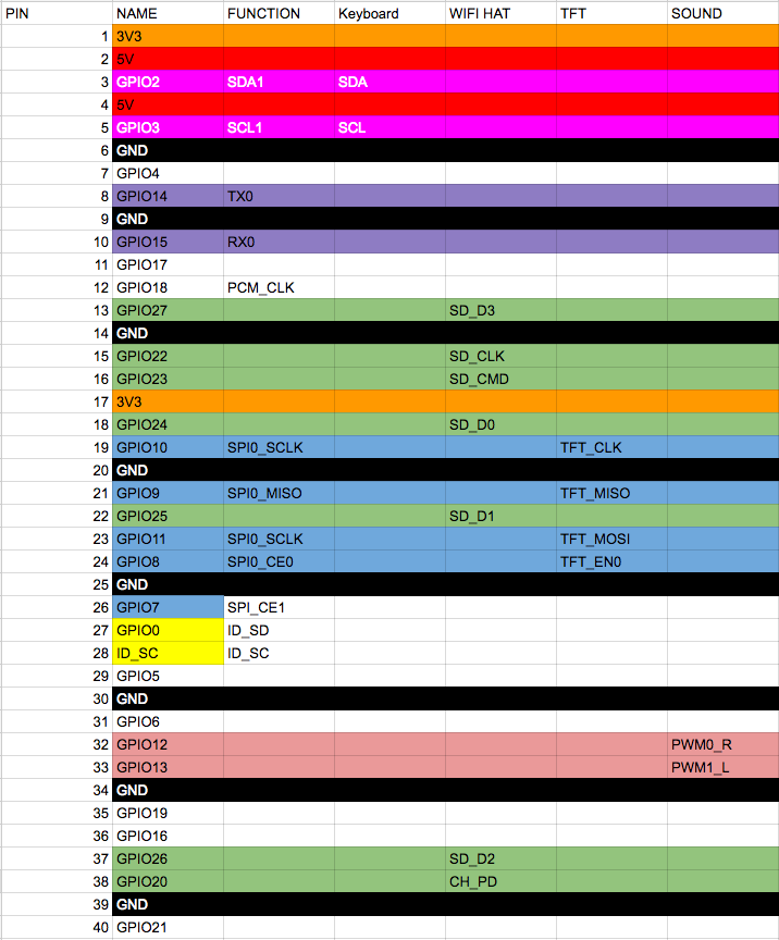
| WiFi | 👍🏼 | |
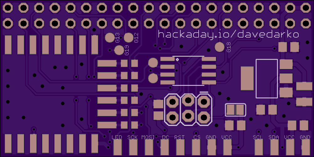
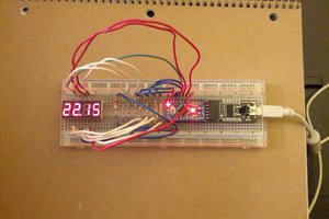
| Display | 👍🏼👎🏼 | |
| Attiny Display brightness controller | 👍🏼 | |
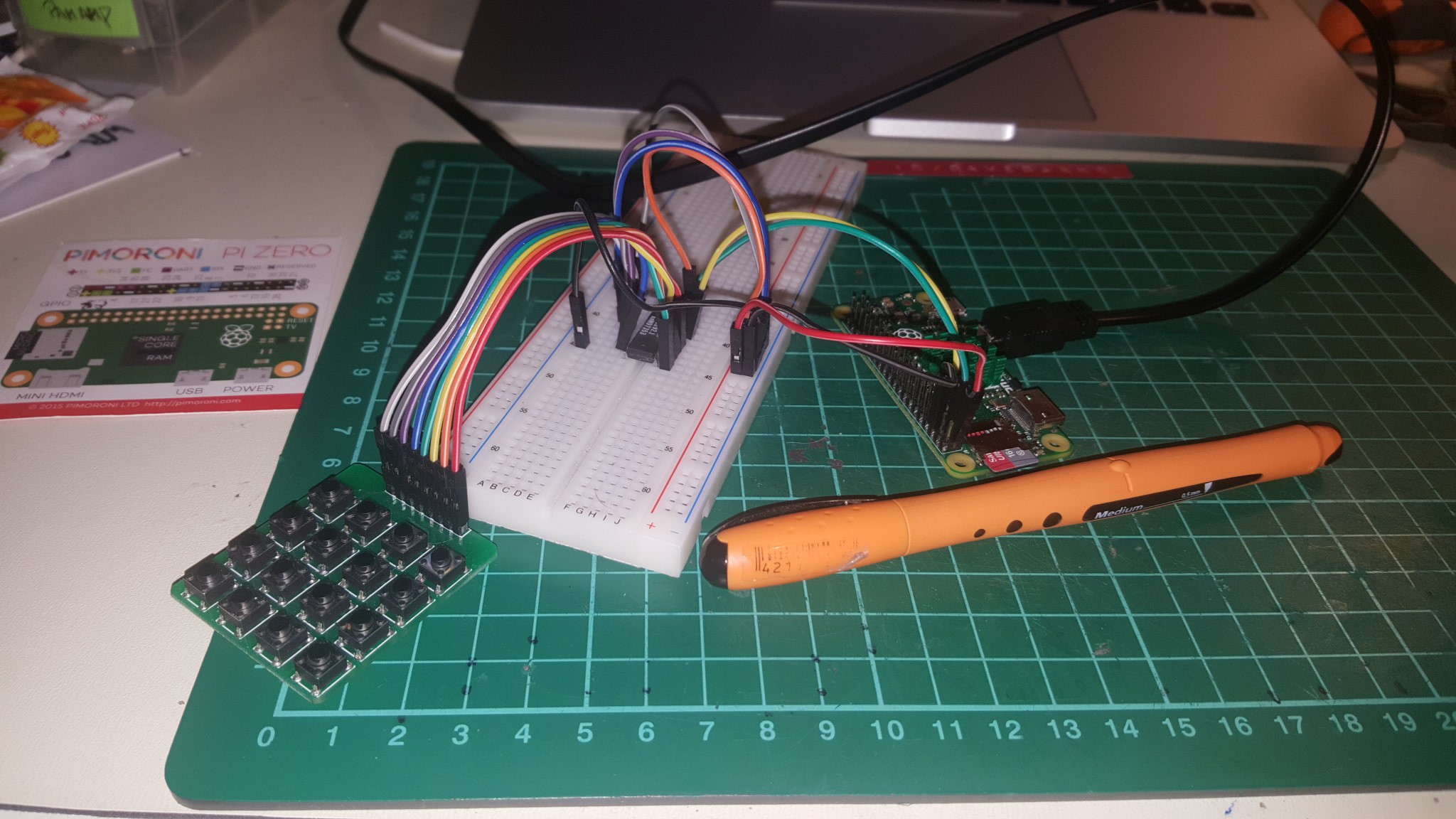
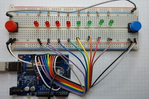
| Keyboard over I2C | 👍🏼👎🏼 | |
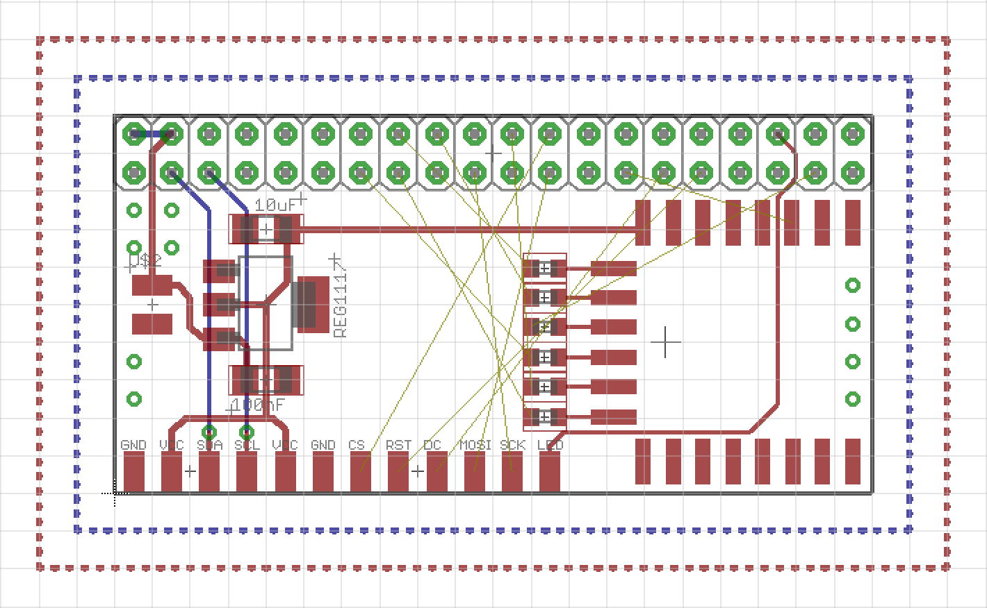
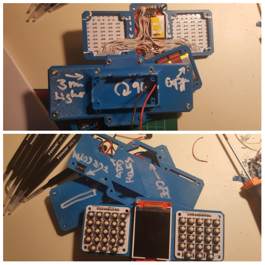
| Power | 👍🏼👎🏼 |
0%
0%
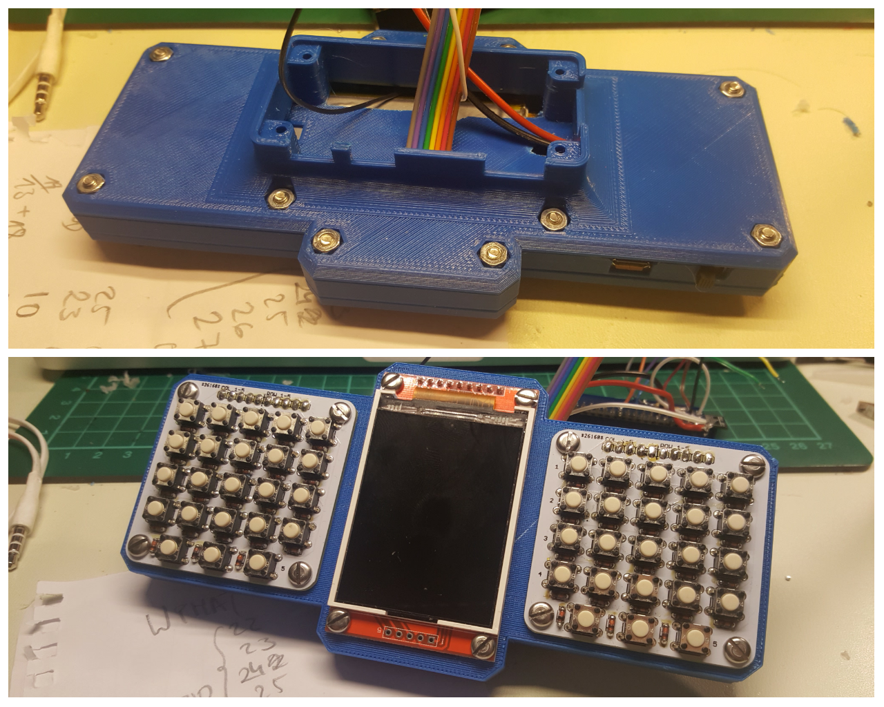
Portable Raspberry PI Zero
a 3D printed portable computer with a QWERTY keyboard
Become a Hackaday.io member
Already have an account? Log in.
Just one more thing
To make the experience fit your profile, pick a username and tell us what interests you.
Pick an awesome username
hackaday.io/
Your profile's URL: hackaday.io/username. Max 25 alphanumeric characters.
Pick a few interests
Projects that share your interests
People that share your interests


 Hari Wiguna
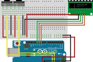
Congrats on making the finalist list mate!
You'll have to somehow work that Pi Camera into this now :-)