 davedarko
https://docs.google.com/spreadsheets/d/1G__6bgoXlyRspCsvcebNKyEUlDYK1BtcHlGwnXLq2EA/edit?usp=sharing
https://hackaday.io/project/8678/instructions
http://marcosgildavid.blogspot.de/2014/02/getting-ili9341-spi-screen-working-on.html
https://learn.adafruit.com/introducing-the-raspberry-pi-zero/audio-outputs
All that Pin X is GPIO Y got me confused... so I had to "map" the pins.
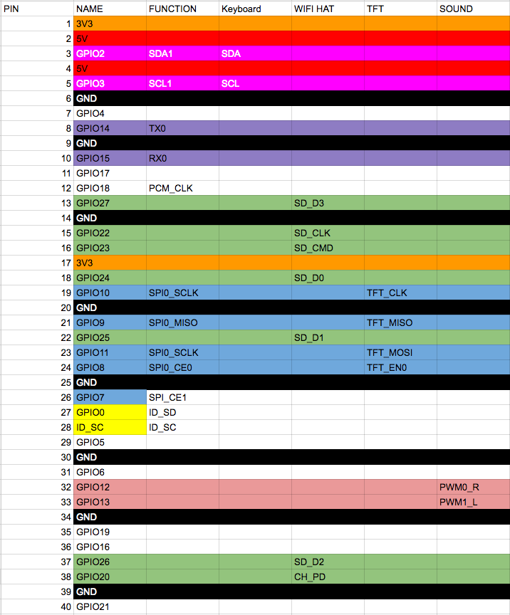
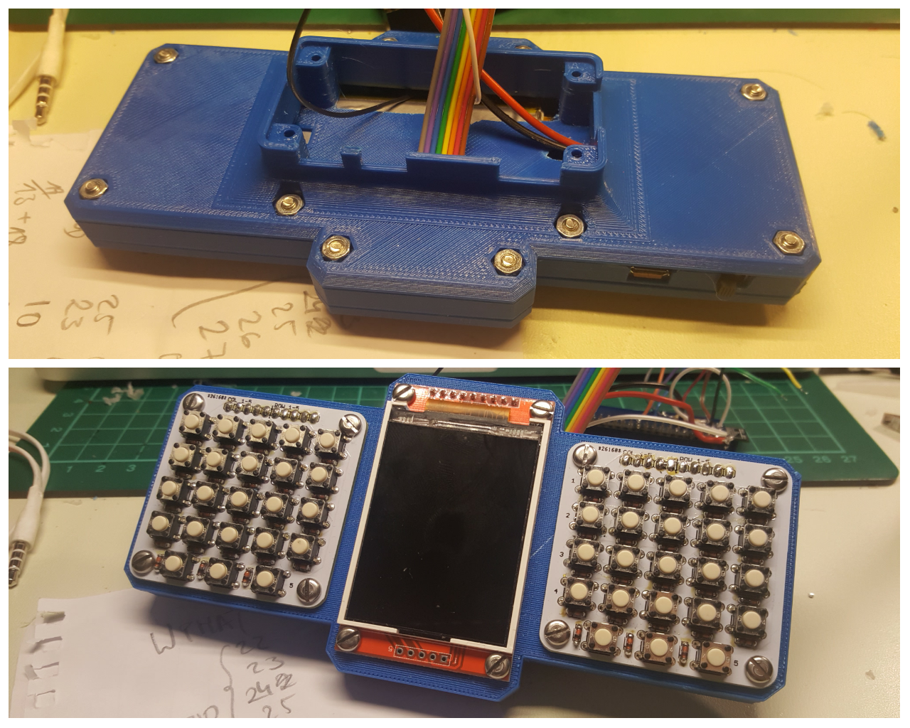
Nothing but the keyboard works yet.
Here's the closed case.
Discussions
Become a Hackaday.io Member
Create an account to leave a comment. Already have an account? Log In.
So, you are going to use PWM sound output, after all?
I noticed you are planning to use GPIO12 and 13 for this, which are ALT0 functions for PWM0 and PWM1 - so the most obvious way of getting the PWM output. Interesting enough, adafruit tutorial, #PiBoy-Zero and some other sources are using pins GPIO13 (ALT0) and GPIO18 (ALT5). Is there a reason to omit PWM function of GPIO12?
Are you sure? yes | no
Yes, seems like I can use them! I was confused by all the GPIOXX is on physical PINYY and so on, that I thought pin 18 and 13 were already in use by the ESP. Then again I thought I couldn't use the ESP anymore because of the SPI pins and so on... so I made a list.
I just like that the pins are close together on the board - I'm a bit confused though, it is crossed off the GPIO list on their link, but it's clearly on the PI zero - I'll just have to experiment with the pinout stuff. I will first try to get it working on PIN 18 and 13 and will then see if I can change them to 12 and 13. I could always add an attiny85 via I2C for LED PWN and maybe check the battery with that as well.
Are you sure? yes | no