 Patrick Van Oosterwijck
So in a previous project log I had been trying to figure out how to design this without a proper gate driver, and drive the charger MOSFETs directly from the micro.
I have since come to the conclusion that this is a stupid idea. :) In the log referenced above, I mentioned two purposes of a gate driver:
- Provide level shifting to drive the gates with sufficient voltage.
- Provide powerful drivers that can quickly charge and discharge the power MOSFET's gate capacitance, to ensure fast switching for high efficiency.
The latter is what made driving the gates directly from the microcontroller already look bad. But there's another function gate drivers provide that I had forgotten:
- Provide a floading well for the high side MOSFET gate driver!
Level shifting the high side gate drive signal does not just involve shifting the high level, but the source voltage for this MOSFET (and "ground" reference for the driver) is shifted as well every cycle!
Details can be found in the Wikipedia article on buck converters, but here's the graph from it:
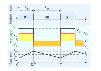
As you can see, the switching node voltage (Vd in the graph) continuously switches between 0V and Vi, which in my case can be up to 28 V. The gate driver ensures that the high side MOSFET gate keeps the correct voltage level relative to Vd, no matter what Vd is doing.
Proper gate drivers contain a special circuit feature called a floating well that takes care of this and a level shifter that translates the incoming PWM signal into a signal that is referenced to this node that's bouncing up and down. There's just no way that I can easily replicate this functionality without using a gate driver. Turns out people knew what they were doing when they started making these parts and they exist for a good reason. :)
MIC4600 solution
My biggest objections to adding a gate driver were cost and PCB space. When I started searching for gate drivers that would work with my minimum signal voltage levels of 1.71 V and maximum input voltage of 28 V, I quickly found out that there was a good reason I had chosen the MIC4600 in the customer project this is based on: it's pretty much the only part on the market that fulfills both requirements. Unfortunately, the lowest price I've seen for them is $0.978 in qty 1000. That's a significant cost adder.
I wanted to know what else was out there. What was I missing out on with my extreme requirements? Were there any requirements I could relax just a bit so a lower cost part could work?
NCP81151 solution
So I removed my search filters and went for the lowest cost suitable part i could find: the NCP81151, which is only $0.175 in qty 1000! In addition to the low cost, it has some other advantages. It's a synchronous driver which means that instead of having to control both high and low side MOSFETs from the micro, I can provide a single PWM signal and the gate driver will manage the high and low side drivers by itself. In addition, it has zero cross detection on the low side driver which makes it automatically behave correctly if the system goes into discontinuous mode (inductor current falls to zero). This is a really big deal to me because there's no good way I know to handle this from the micro other than to estimate and run in asynchronous mode for low currents and synchronous for high currents. Having the zero cross detection makes this headache go away.
What would it take to make this part work in my design? The first obvious thing: it requires 5 V, not 28 V. The floating well can take 35 V so my input voltage range is fine, but I need a voltage regulator to supply the gate driver itself. In some way this isn't any different from the MIC4600. It also runs from 5 V, but has a regulator integrated on the same chip.
I need a regulator that works from 4.5 V to 28 V, has an enable pin that works with 1.71 V input signal, and low shutdown current when turned off. There are many dirt cheap regulators, but it turns out that the requirements above push me to higher cost parts. The cheapest I could find was the RT9069, which is $0.30 in qty 1000. That's almost double the cost of the gate driver, which makes me feel a little ill. Any suggestions for lower cost parts that fit the bill would be very welcome. But, we're still well below the MIC4600 cost, so let's continue the exercise.
I also need a level shifter for the PWM input pin. The PWM input is a weird deal with three input levels. To take advantage of the zero cross detection, I need to switch between the high and middle levels. Anything else would have been better to be honest.
The low cost SGM4552 seems to do the job in going from 1.71 V input to 5 V output. To switch to the middle level for low, I think I can add a simple 2 V zener diode circuit to make this work. Those two add another $0.08 or so in qty 1000.
So we're at a total of $0.555 for the NCP81151 solution.
Which one to choose?
Board space is tight in my current floor planning, so the MIC4600 solution is the front runner in that respect. But the synchronous driver and zero cross detection of the NCP81151 solution are very appealing, at nearly half the cost.
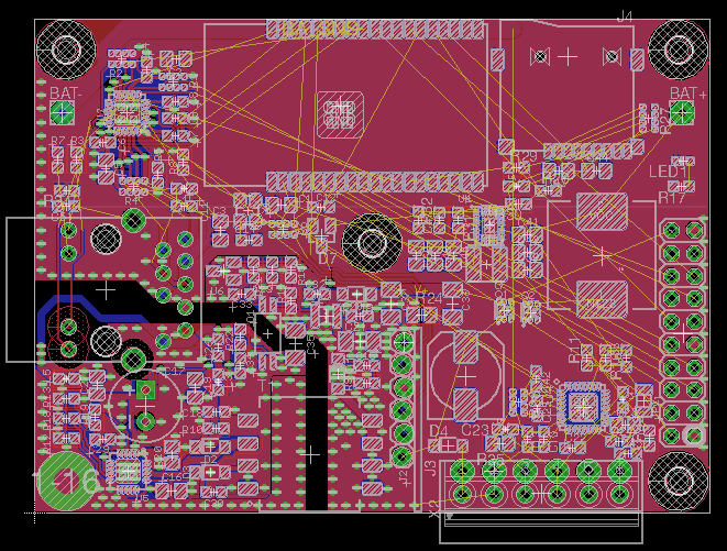
The screenshot above shows my current floor plan without any gate drivers. As you can see there's very little room to spare. I will have to make footprints for the relevant parts and see what can be done. It may be necessary to grow the board.
Discussions
Become a Hackaday.io Member
Create an account to leave a comment. Already have an account? Log In.