 Patrick Van Oosterwijck
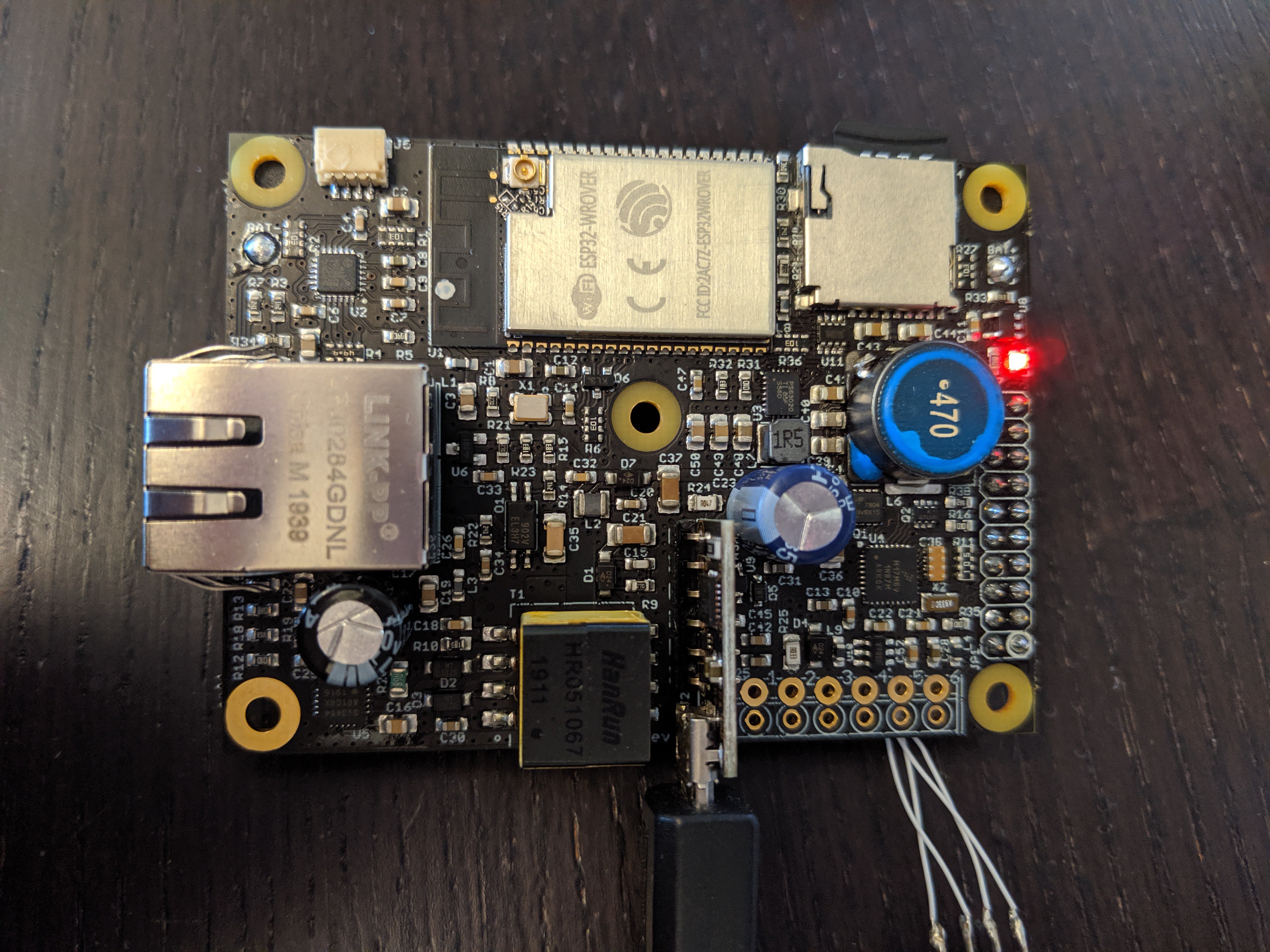
The 10 prototypes arrived from KingTop, so it was time to see what doesn't work. ;)
The first thing I did was plug in a PoE cable, to check whether that section works. 5V was showing up on V+, so that was one down! This was a simple one because the PoE section is pretty much a copy of the #wESP32 circuitry, only with a smaller flyback transformer.
Time to connect a battery and my J-Link and see if I can talk to the charge/system controller:
And we have a blinking LED, excellent!
From there, I started to write some firmware to check stuff and turn various parts of the system on and off. I verified I can go to sleep and wake up with the 32 kHz crystal, I can turn various parts of the measurement system on and measure input voltage and current and battery power and current. I can turn the switched battery output on, and the power for the gate driver.
I hit my first snag when I tried to turn the 3.3V system power for the ESP32 on. Suddenly, there was a lot of heat near the buck-boost converter. Uh-oh! Luckily, I have a thermal camera to figure out where exactly the heat is coming from:
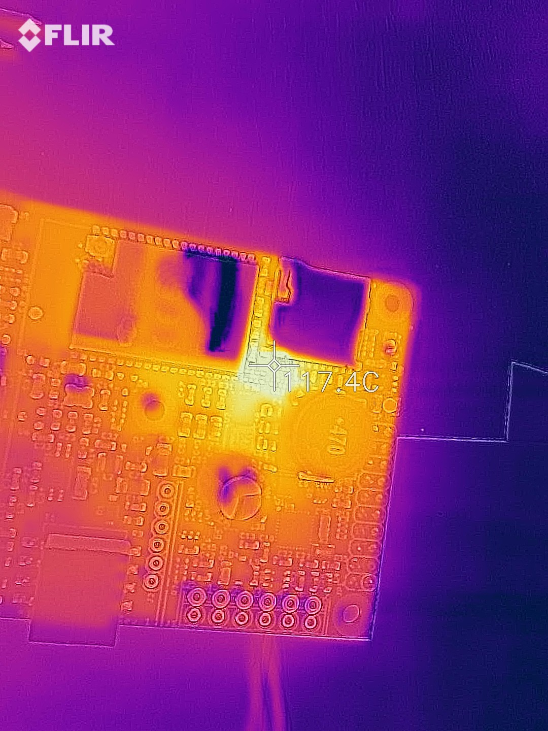
That's not the buck-boost converter, it's the little I2C level shifter U11 that's trying to burn up! What's up with that?
Upon closer inspection, turns out KingTop messed up this time. On 4 of the 10 boards, the level shifter was mounted 180 degrees turned. Doh!
This particular chip was fried, so I replaced it with another one on my test board. Tried to turn the 3.3V system power on again, no heat this time! 3.3V on the system supply from a 3.2V battery, the converter is doing its job. Time to test it under some load, let's pull 1.1A in addition to what the ESP32 is pulling:
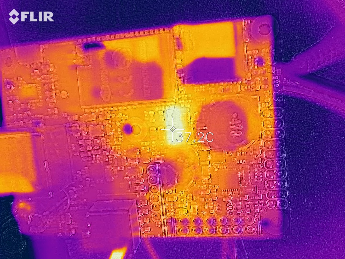
37°C at 1.1A, that chip isn't even breaking a sweat! Of course, more testing will have to be done over the full 1.7V to 3.6V input range, but this is very positive.
Once I had system power, I could start testing the rest of the board. The ESP32 programmed right away through the wESP32-Prog submodule. I put MicroPython on it again for testing, very convenient. I connected Sparkfun's Environmental Combo Breakout to the Qwiic connector and a scan of the bus reported 2 devices. I hooked up an antenna to the U.FL connector and connected to an access point, got an IP and was able to load data.
I had some trouble with the micro SD card at first. Various guides talked about an SDCard object that didn't seem to exist in my MicroPython. Turns out this is pretty new, so I went looking for the latest image. I found that there are now official images with PSRAM support available! Woohoo! Loaded the latest one, and now MicroPython reports 4M free space instead of 150K, awesome! Also, the SDCard object exists in this image and I could load a file from the SD card.
The only major parts that haven't been checked yet are the charging system and the Ethernet PHY. Both require some firmware work on the charge/system controller first. But the first tests have been very positive up till now.
One other thing I'm still trying to figure out is high sleep current on the system/charge controller. I'm getting ~270 μA sleep current while I was expecting only a couple μA. I have checked by removing supply ferrite beads and about 166 μA is going into the controller's digital VDD and 60 μA into the analog VDDA. I'm not sure yet where it's going. These modern chips are so complex with a gazillion things that can be or need to be turned on and off manually and it's likely I've screwed something related to that up in my code.
Discussions
Become a Hackaday.io Member
Create an account to leave a comment. Already have an account? Log In.