 Patrick Van Oosterwijck
Finally found some time to test the rest of the board and things are looking good!
Charging subsystem
The first thing I tried to get to work was the charging subsystem. I hit my first snag there. In my last update I reported that I could turn power for the gate driver on. I don't know what exactly I checked that time (maybe just that the enable pin to the gate driver regulator toggled), but turns out that was a lie. :)
What really happened was that yes, I could control the enable, but with voltage present on V+ no voltage would appear on the gate driver's supply. Very puzzling. Until I looked at the datasheet for the AP7383 regulator and figured out I had messed up my footprint! I was sending the enable signal to the NC pin instead of EN! Doh!
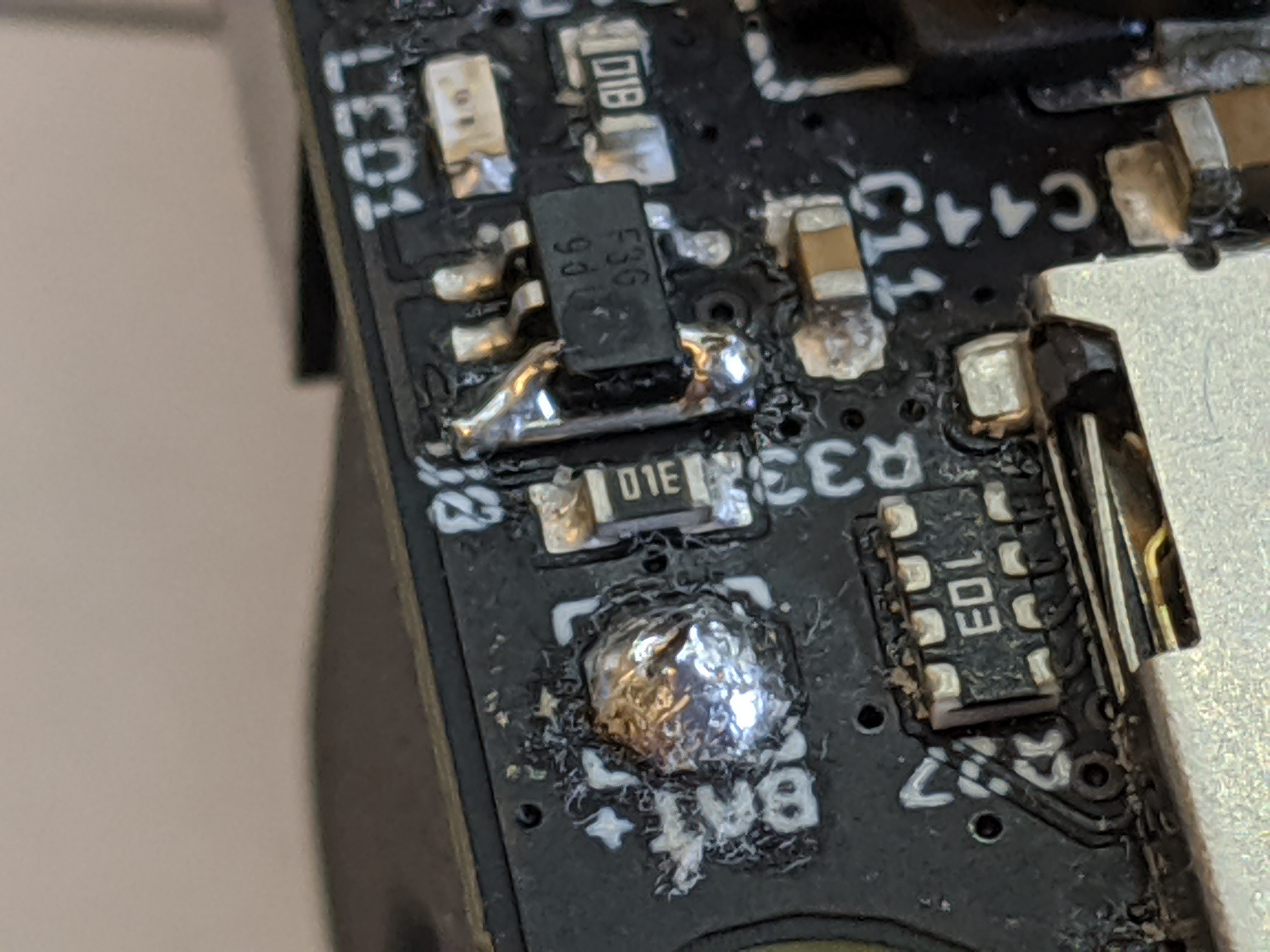
So much for the rev 1 PCB design, on to rev 2. Luckily, it's easy to fix on the 10 rev 1 boards I have:
So now I had power, I could start testing the charging subsystem. I wrote a bit of code to produce a PWM signal and set it to 100/255. Here's what the signal on the NCP81151 gate driver's PWM pin looked like:
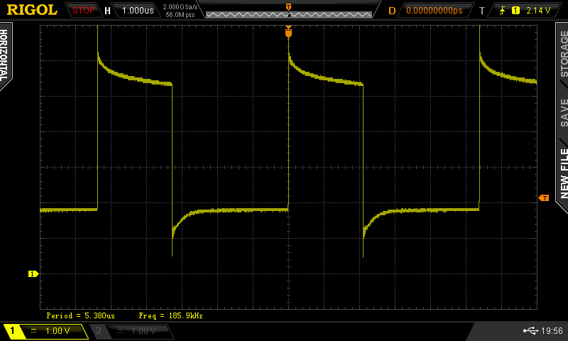
Excellent. Exactly the weird signal levels required. :) Recall that to use the synchronous rectifier's zero cross detection, the low level on the PWM input needs to be between 1.3V and 2.7V. Looks like we're nicely between those levels.
In discontinuous mode, the synchronous rectifier needs to be turned off so we don't start pulling energy back out of the battery once the inductor current dies. Looking at the switching node voltage we can see that indeed the synchronous rectifier is turned on, then releases, when in discontinuous mode:
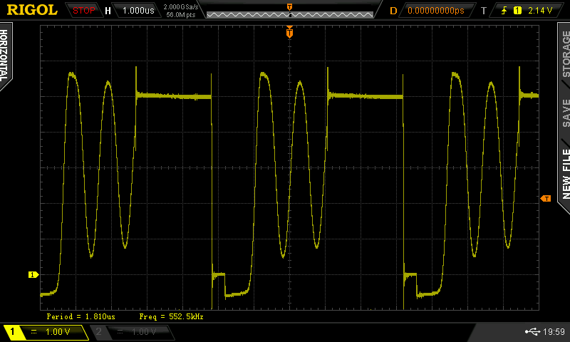
The flat high part (5V input) is when the high side driver is pushing current through the inductor. Right after that we see a short stretch of 0V, this is when the low side synchronous rectifier is turned on. This was confirmed by looking at the gate signal. After the current through the synchronous rectifier gets low enough (zero cross detection), it is turned off and we get any remaining current flowing through the body diode, showing as -0.6V, after which the inductor voltage just oscillates a bit until the next cycle starts.
Since I didn't have any control loop controlling the PWM yet (I just had it at a fixed value), I raised the input voltage to get the system into continuous mode. Here's the switching node voltage in that condition:
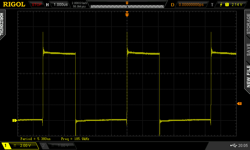
The same on-time for the high side driver, but at around 8.5V input. Now there's enough magnetic energy stored in the inductor to keep the current going through the remainder of the cycle. As you can see, the synchronous rectifier stays on and the voltage is 0V for the rest of the cycle.
In this condition, I checked the voltage across the battery's current sense resistor and measured about 12mV. For a current sense resistor value of 0.033 ohm, this means we were pushing about 360mA into the battery--it was charging! :) Indeed, when looking at the battery voltage, I could see the millivolts counting up.
I checked that the gate driver starts to operate at around 4V V+ input voltage. This is great, I was planning to specify a minimum 4.5V input voltage. So what this testing shows is that the charging hardware seems sound, all I need now is to implement the software MPPT control loop!
Ethernet PHY
The last main subsystem I hadn't tested yet was the Ethernet PHY. From the #wESP32 I had already learned that this part is kinda finicky when it comes to its initialization. In this project, I didn't add a dedicated part to handle this but am using the main charge/system controller to do it. This is so its state is under user control and it can be enabled when necessary and doesn't such power when it's not in use.
So I added some code for the bring-up and plugged in an Ethernet cable. Nothing. I fiddled with various things like the oscillator for a while until I eventually replaced the PHY chip and it started to work!
I tried a couple other boards and they didn't work right either, but what I eventually found out is that I needed to program the ESP32 on those boards, and then the PHY would work! It seems that from the factory, the ESP32 must contain code that sets the pins in a certain way that makes the PHY not work correctly.
Still, on my first board, I'm pretty sure I already had programmed the ESP32, and it still didn't work. Now I'm not sure what happened there, maybe that board just happened to have a bad chip on it. But after programming and testing with the other previously unused (and unabused) boards, I can say with pretty high confidence that the Ethernet PHY is working! I also got an IP address and was able to pull data from the Internet.
I2C communication
One last thing I hadn't done before, but that's vital to the operation of the board, was try I2C communication between the ESP32 or 3.3V power domain, and the system/charge controller or battery power domain. There's a bidirectional level shifter in between to make that work.
I had to write a bit of code to get minimal I2C functionality on the system/charge controller. All I did was save the last byte written, and echo the value back on a read request. Then I tried to access the controller from the ESP32. This also didn't seem to work at first, the signal would not cross the level shifter. Turns out it worked fine on the previously unused boards as well though, so just a bad chip on my main dev board. It seems I've been quite hard on the poor thing while I've been fooling around testing stuff. :)
So I think the verdict is that rev 1 hardware is quite functional! Only one little mess-up that can be fixed easily. Time to get cranking on the firmware so I can really start putting this thing through its paces and evaluate charge efficiency, input voltage range, output power range, optimize and evaluate low power performance, etc.
Discussions
Become a Hackaday.io Member
Create an account to leave a comment. Already have an account? Log In.