Close
0%
0%

OpenEyes

Open source visual aid platform

Similar projects worth following
Openeyes is an open source hardware platform aimed at developing solutions to aid visually impaired individuals using off the shelf hardware and machine learning algorithms.
While each form of impairment has it’s unique challenges, the platform aims to solve three core problems: spatial perception, identification, and navigation.

Every aspect of the hardware is going to be open sourced as it is developed and software is built around ROS, enabling the use of industry standard robotics packages such as cartographer or the navigation stack while keeping the solution modular and easy to extend.

According to the WHO there are over 1.3 billion visually impaired worldwide with various levels of impairment, some can recognize the shape of objects from but have no spatial perception, some do not have any peripheral or night vision, some have no central vision. Many of these conditions are degenerative, and many of those affected are located in third world countries.

The most widely used solutions are still guide dogs, which are incredibly expensive to train, and white canes. There are a couple of hi-tech solutions on the market. The more ambitious of them are either region restricted or plain vaporware. The others are limited to one use case such as reading text, or counting steps. So there’s definitely a need for an integrated open source solution. 

While it's hard to pinpoint the exact requirements of each condition, there are three core problems that the system is trying to solve: Spatial Perception, Identification, and Navigation

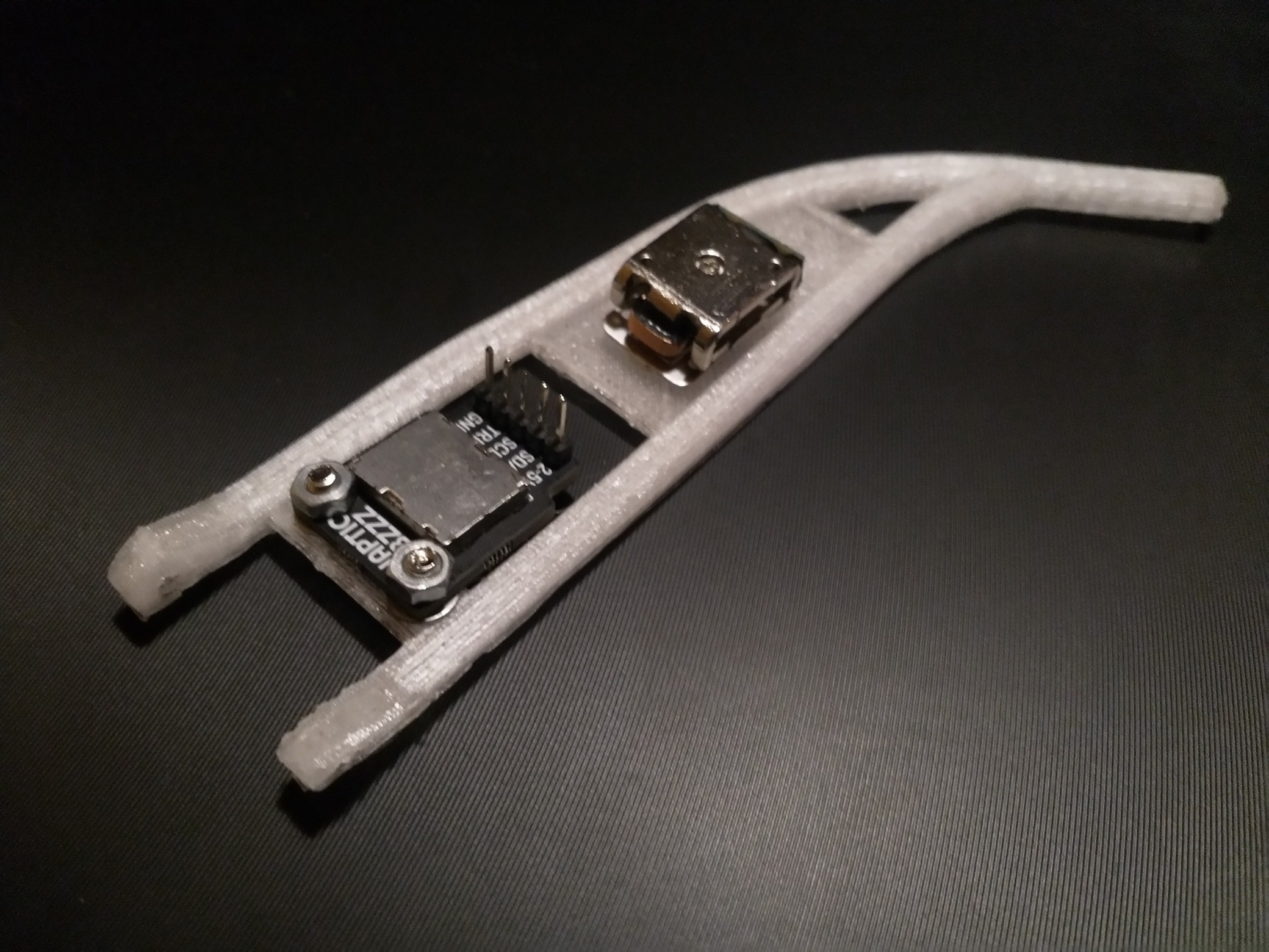
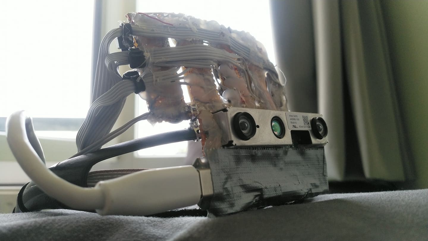
Instead of translating the information needed spatial perception from a sense to another Openeyes replaces it with the same concepts that are used for localization in mobile robots and drones. This implementation is centered around the Realsense T265 camera which runs the V-SLAM directly on the integrated FPGA. This works similarly to how sailors used to navigate using the movement of the stars and their position. Instead of the stars, there are visual markers, instead of the sextant there are two stereo cameras and instead of a compass, there’s an inertial measuring unit  A USB connection streams the data to the connected SBC and provides information for the kinematics system. This can be the propellers of a drone or a differential drive motors on mobile robots. In this case, the output is translated into proportional vibration patterns on the left and right rim of the glasses. 

V-SLAM is awesome but it does not cover every requirement for a complete navigation system. Another Realsense camera, the D435i provides a high accuracy depth image that is used for obstacle avoidance and building occupancy maps of indoor environments. Using voice control the users can choose to save the positions of different objects of interest and later navigate to them. With a GPS module, this could be implemented for outdoors later. 

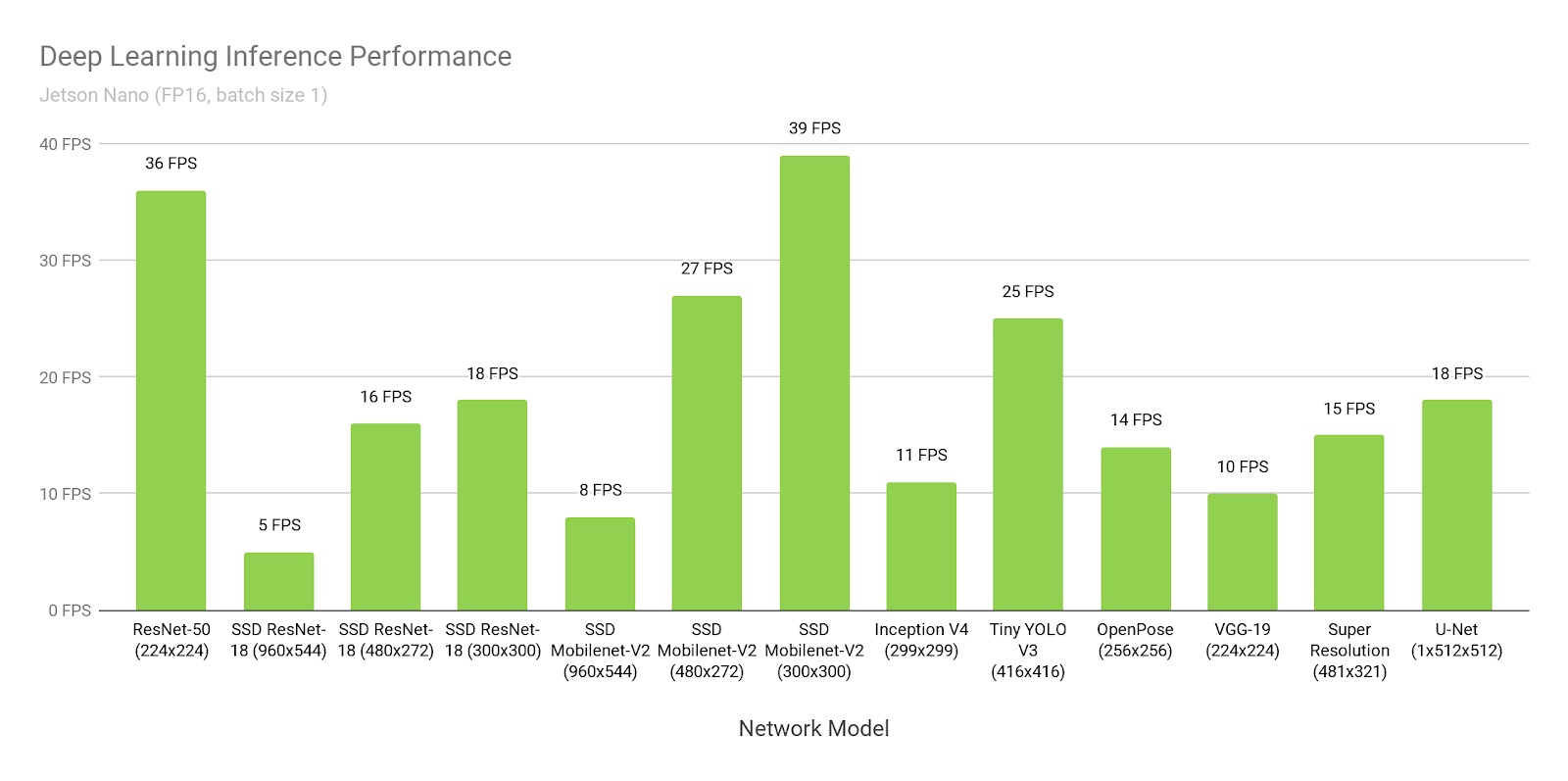
Identification is another issue of the visually impaired that the system aims at aiding with. This is clearly to be done by a deep convolutional neural net. There’s plenty of network options available, such as ImageNet, ResNet, Yolo. I chose the Nvidia Jetson Nano because it contains 128 standard CUDA cores, which is supported by all of the popular deep learning frameworks and can run most of the networks at around 30 FPS. The goal of the system is to detect objects and be able to name them but also detect stairs, street crossings and signs adjusting the parameters of the navigation as needed.

full_assembly.dwg

DWG Drawing - 29.69 MB - 08/25/2019 at 13:33

Download

nose_piece.dwg

DWG Drawing - 1.55 MB - 08/25/2019 at 13:33

Download

left_arm.stl

Standard Tesselated Geometry - 149.50 kB - 08/25/2019 at 13:33

Download

left_arm.dwg

DWG Drawing - 232.56 kB - 08/25/2019 at 13:33

Download

front.dwg

DWG Drawing - 587.67 kB - 08/25/2019 at 13:33

Download

View all 9 files

  • 1 × Nvidia Jetson Nano Single board computer with 128 CUDA cores
  • 1 × Intel Realsense T265 Stereo camera with integrated FPGA that performs V-SLAM
  • 1 × Intel Realsense D435i RGB-D Camera
  • 1 × Adafruit Itsy Bitsy M4 Microcontroller
  • 2 × Pimoroni Linear Actuator Haptic Breakout Haptic Actuatior and Controller

View all 7 components

  • CAD and 3D printing done

    cristidragomir9708/25/2019 at 13:28 0 comments
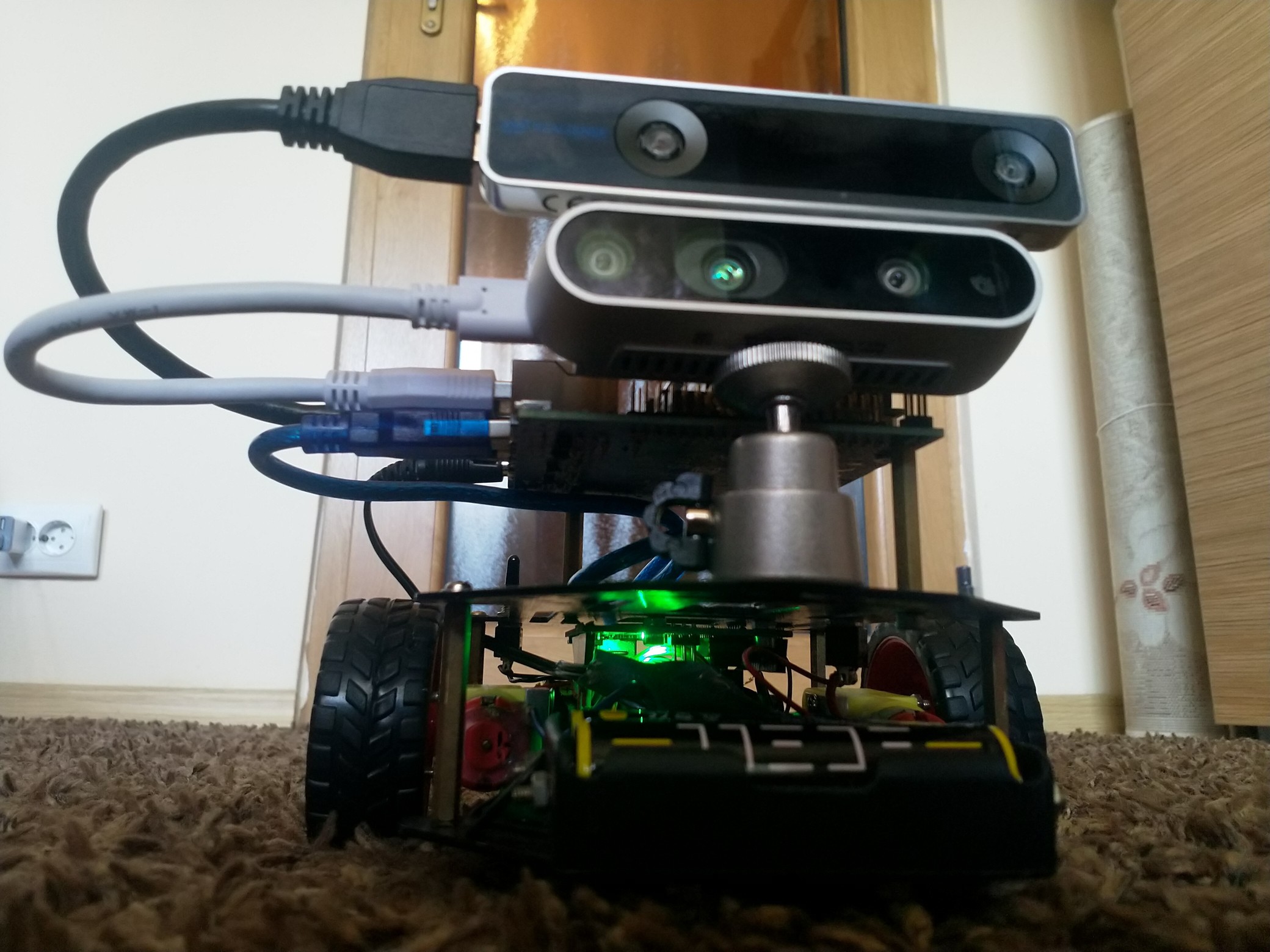
  • ROSie

    cristidragomir9708/25/2019 at 12:15 0 comments

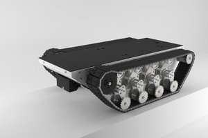
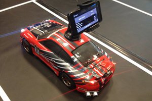
    One day while I was at my parents place cleaning up, I found an old robot platform that I didn't get to use yet.

    Integrating the SLAM data from the T265 and the depth information from the D435i, with the ROS stack might be a challenging enough task on its own. A simple mobile robot platform with differential kinematic would be the perfect starting point for exploring this without the other challenges of the entire system

    So here's ROSie.

  • New concept

    cristidragomir9708/24/2019 at 15:53 0 comments

    After building a cool looking but pretty useless prototype, and asking myself a couple of serious questions about the aim of the project, I finally boiled everything down to a concrete goal. The system should solve three core problems of the visually impaired: spatial perception, identification, and navigation. 

    While the previous implementation was focused on translating spatial perception from one sense to another, the current one is aimed at completely replacing it with the same concepts that are used for localization in mobile robots and drones. This implementation is centered around the Realsense T265 camera which runs the V-SLAM directly on the integrated FPGA. This works similarly to how sailors used to navigate using the movement of the stars and their position. Instead of the stars, there are visual markers, instead of the sextant there are two stereo cameras and instead of a compass, there’s an inertial measuring unit  A USB connection streams the data to the connected SBC and provides information for the kinematics system. This can be the propellers of a drone or a differential drive motors on mobile robots. In this case, the output is translated into proportional vibration patterns on the left and right rim of the glasses. 

    V-SLAM is awesome but it does not cover every requirement for a complete navigation system. Another Realsense camera, the D435i provides a high accuracy depth image that is used for obstacle avoidance and building occupancy maps of indoor environments. Using voice control the users can choose to save the positions of different objects of interest and later navigate to them. With a GPS module, this could be implemented for outdoors later. 

    Identification is another issue of the visually impaired that the system aims at aiding with. This is clearly to be done by a deep convolutional neural net. There’s plenty of network options available, such as ImageNet, ResNet, Yolo. I chose the Nvidia Jetson Nano because it contains 128 standard CUDA cores, which is supported by all of the popular deep learning frameworks and can run most of the networks at around 30 FPS. The goal of the system is to detect objects and be able to name them but also detect stairs, street crossings and signs adjusting the parameters of the navigation as needed. 

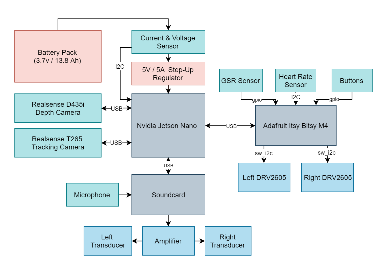
    The following hardware platform is going to support the functionality:

  • First Prototype

    cristidragomir9708/21/2019 at 17:37 0 comments

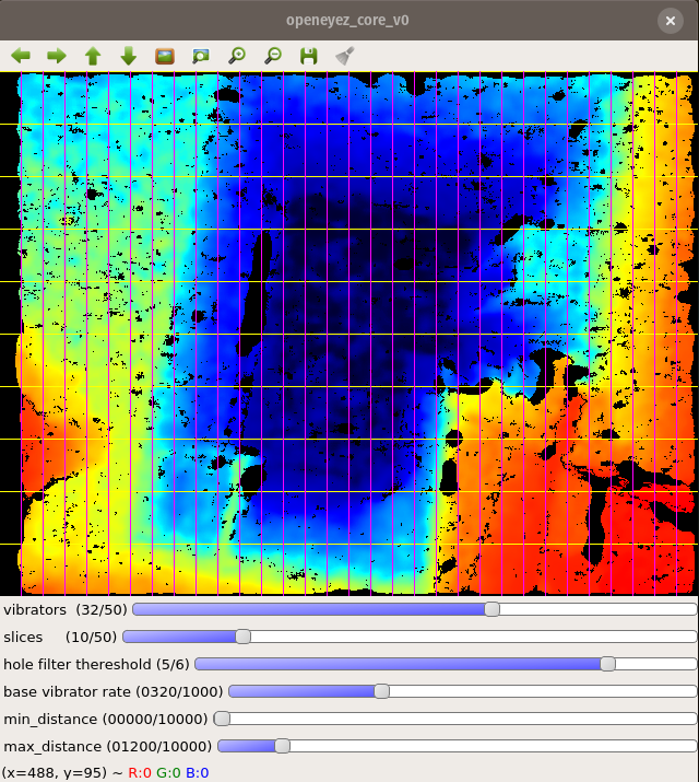
    Originally, my idea for this system was to take the frames from a depth camera, split them into a 2D grid that corresponds to the arrangement of the vibration motors, and then make a weighted average of the distances in each cell. 

    The resulting output would be translated into proportional vibration rates for each motor in the grid.

    The software took a couple of hours to develop, however building the vibration matrix turned out to be a more complex task then I expected. 

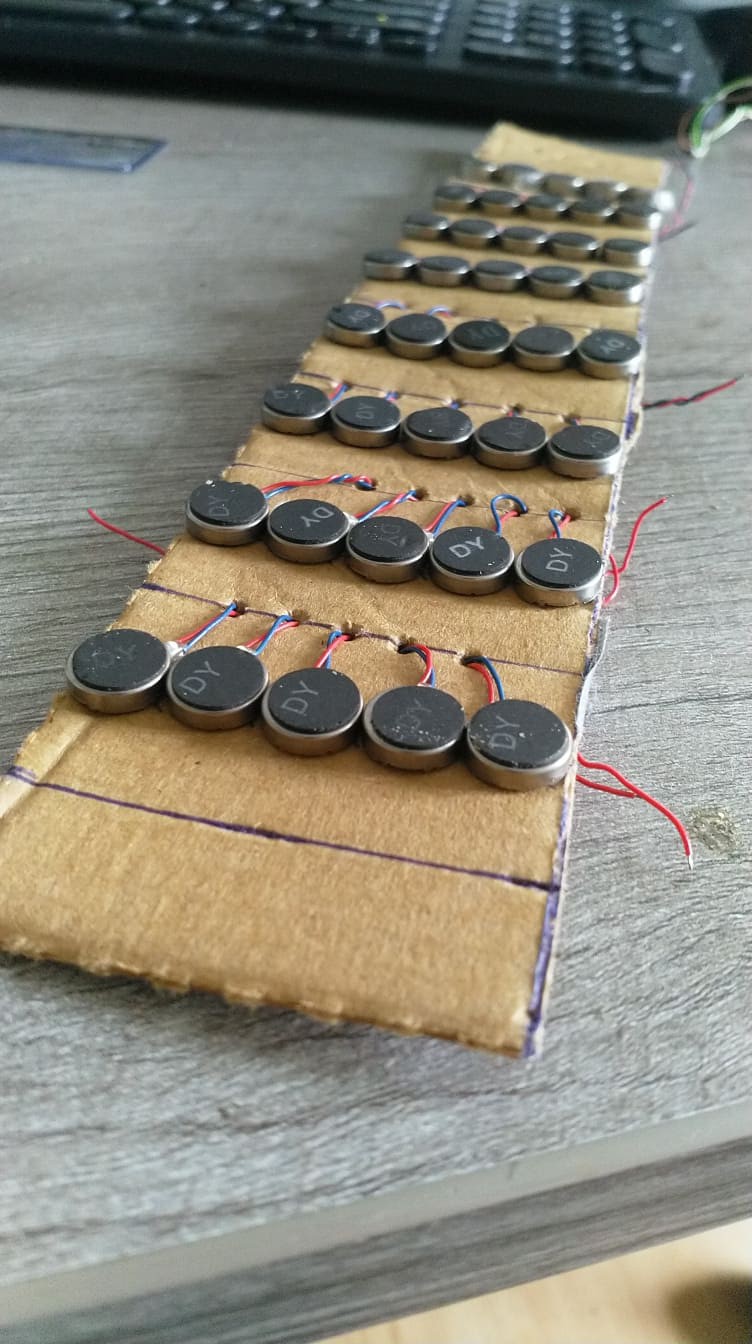
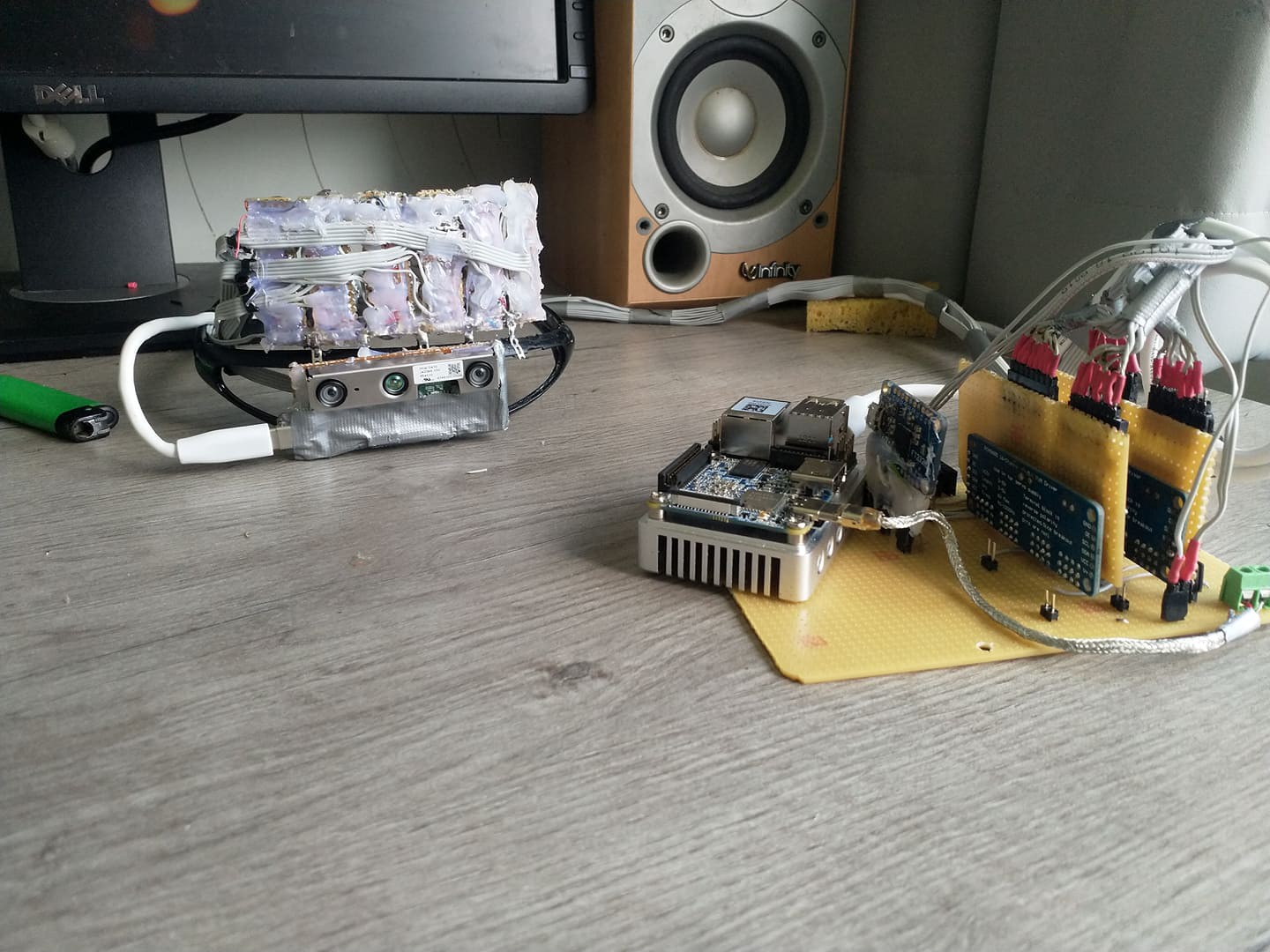
    My first idea was to put all the motors on a piece of cardboard (pizza box to be completely honest).

    After painstakingly soldering all the leads, I proceeded to connect the wires to a couple of PCA9865 based PWM controllers and ran the default test that runs all the channels in a wave.

    It felt like the whole thing was vibrating, distinguishing unique motors was impossible. Maybe if I test with one motor at a time? Nope, I could distinguish it was on the first two columns and somewhere on the upper side, and that was about it. I also found out that between every couple of tests, leads from the motors would break, leaving me with random "dead pixels"


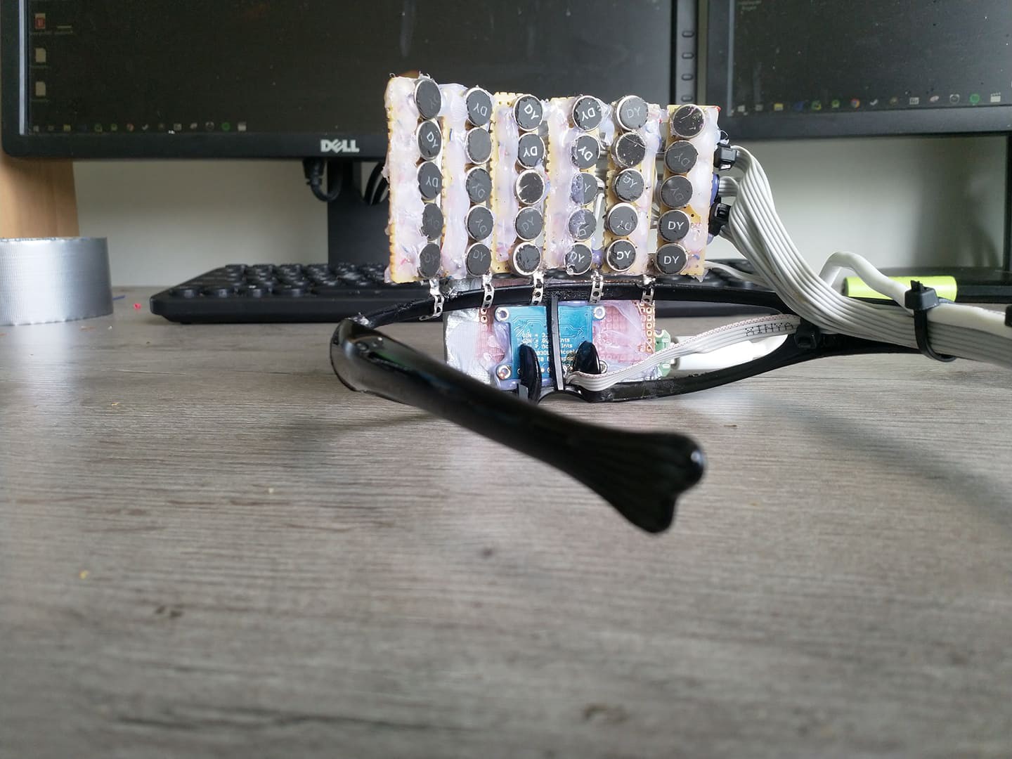
    I figured putting all the motors on the same surface was a really bad idea, so I carefully removed them all and started again. 


    Fast forward two weeks and a couple of component orders later, and I had a working prototype. The new construction of the vibration matrix turned to be less prone to vibration leaks, and "passed" all the wave tests. The RK3339-based NeoPi Nano turned out to be powerful enough to process the feed from the depth camera without dropping frames. Time to integrate the haptic display with the image processing code.

    Here's where it became clear that the matrix of motors wasn't a solution.

    While the origin of vibration was identifiable while testing with pre-defined patterns, the real-life feed was a whole different story. 

    First off, it was clear early on that modulating the intensity of each motor was not a solution because motors with low intensity wouldn't be distinguishable if surrounded by one or many with high intensity. 

    Instead I opted for modulating the rate, similarly to the way parking sensors in cars work. 

    However, tracking the rate of 30 different sources in real-time is quite a cognitive task, and it gets tiring after a short while. (aka, wear it for long enough, and you'll get a headache)

    Another issue was that while walking or simply rotating the head, frames would change faster than the lowest rate of some motors, so they wouldn't get to vibrate enough for the wearer to get a sense of the distance before the distance would change again. 

    Tweaking the min/max rate turned to be a fools' errand, because what seemed as ideal to some cases, for example, a room full of objects, was a disaster to others, such as hallways and stairs. Tweaking the rate in real-time could have been an option, but I assumed it would be even more of a dizzying experience. 

    On top of everything, depending on the distance and the number of objects in the frame, vibration leak was still an issue. 

    I was quite disappointed, to be honest, but I still pitched the concept to an incubator inside my university and I even got accepted. 

    Armed with new resources, hope and a lesson learned,  I went back to the whiteboard.

View all 4 project logs

Enjoy this project?

Share

Discussions

Moises Bessalle wrote 08/22/2019 at 13:32 point

looks amazing!!

  Are you sure? yes | no

Similar Projects

Does this project spark your interest?

Become a member to follow this project and never miss any updates