Close
0%
0%

3D printable bearing generator

Generate 3D printable bearings according to your dimension constrains using Fusion 360

Similar projects worth following
Many hobbyist face the problem of needing some bearings that are lightweight and cheap enough for their applications. However, more times than not, the available sizes don´t match your application or they are to much of an overkill to be used. To solve these issues I decided to develop a Fusion 360 script which generates bearings depending on your input parameters.

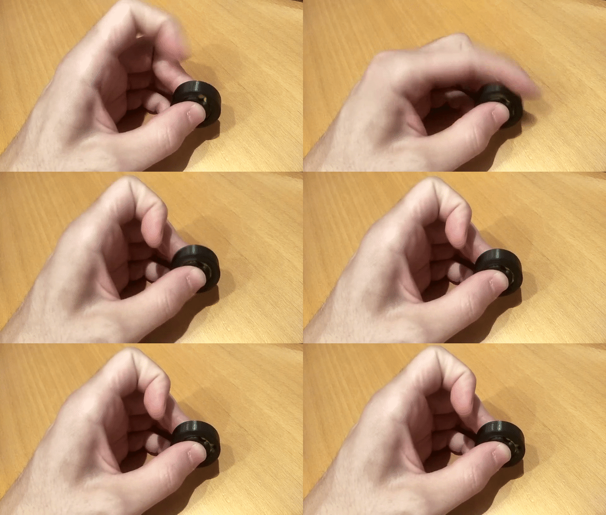
The end result should work like this:
The Fusion 360 script works in a similar fashion as a human designer will design the bearing:

  1. Check the input parameters are correct.
  2. Draw the inner and outer circles and extrude them (create new body operation).
  3. Draw the gap circle and extrude it (cut operation).
  4. Draw the BB ball circle and revolute it (cut operation).
  5. Draw the insertion and extraction circles and extrude them (cut operation).

The execution of the script will result into two parts being generated (the inner and outer part of the bearing).
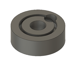
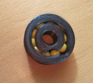
After converting those parts into STL files and 3D printing them, it is time to assemble it together with some BB balls, giving as a result the following bearings:
Bearing generator.py

Script for generating the bearings in Fusion 360

plain - 5.43 kB - 08/20/2019 at 21:18

Download

Bearing generator.manifest

The manifest ile of the script for generating the bearings in Fusion 360

manifest - 252.00 bytes - 08/20/2019 at 21:18

Download

Bearing_outer.stl

A bearing sample. Outer part.

Standard Tesselated Geometry - 1.43 MB - 08/20/2019 at 21:10

Download

Bearing_inner.stl

A bearing sample. Inner part.

Standard Tesselated Geometry - 2.07 MB - 08/20/2019 at 21:10

Download

Bearing dimensions example.png

The bearing sample´s dimensions

Portable Network Graphics (PNG) - 85.12 kB - 08/20/2019 at 21:10

Preview

  • 1 × 3D printer
  • 200 × BB balls * Any size will work

  • Future improvements

    Daniel08/20/2019 at 21:23 0 comments

    As this is an on-going project there is still some things I want to add/improve:

    • Develop a GUI for inputting the bearing parameters.
    • Include an input parameter checkpoint in order to ensure the parameter values and their relations are correct.

View project log

  • 1
    Generate a printable bearing

    Start by downloading and installing the script into your Fusion 360. Check here for a quick guide.

    Once installed open the script and modify the following bearing's parameters inside the script:

    The input parameters to generate the bearing

  • 2
    Assembly

    For the assembly of the bearings follow next steps:

    1. 3D print bearing's two parts.
    2. Remove the support material
    3. Place a BB ball into the outer part's groove and turn the outer part looking for positions in which the ball gets stuck. Clean those positions until the ball is able to rotate freely.
    4. Repeat previous step in the inner part's groove, by placing a BB on it and turning the inner part. Make sure that the BB ball slides smoothly.

    Check outer part´s roughness Check inner part´s roughness

      5. Place the inner part inside the outer part and align the holes.

    Alignment of the bearing parts

      6. Start inserting BBs until there is no more room left. During the process make sure to turn the bearing to detect any kind of blockage. If you encounter a blockage disassemble and check the surfaces again.

    Insert BB balls into the bearing

      7. Finish by inserting BBs until there is no more room left.

      8. Turn the bearing and see if it turns smoothly.

  • 3
    Disassembly

    The disassembly process could be a little bit troublesome depending on the tolerances you used.

    1. Align the insertion holes.
    2. With a thin tool align on BB ball in a way it is below the insertion hole.
    3. With another thin tool push the BB ball from behind though the extraction hole.
    4. Repeat 2-3 steps until there are no BB balls left.

    Disassemble process

View all 3 instructions

Enjoy this project?

Share

Discussions

sasaki takeru wrote 05/23/2020 at 08:40 point

Hello,

I've added some changes.

https://github.com/takeru/BBBallBearingGenerator/commit/40692ed56293c8d2c8b65ae3ba4d56c37f671157

"overhang_angle" for print without supports.

"join bodies" for to export one STL file.

My ball is 5.9mm. dbb = 6.2 or 6.1 is best.

  Are you sure? yes | no

Mike Szczys wrote 08/27/2019 at 10:38 point

Very cool project!

I look at this and wonder about printing on their side, pausing the print to insert balls, and finishing the print. Is this not possible because of overhang and the need to manually smooth the channels?

  Are you sure? yes | no

Øystein wrote 08/21/2019 at 08:00 point

Genius script! Maybe I glossed over something but how do you make sure that balls do not fall out when the to half-circles align?

  Are you sure? yes | no

Daniel wrote 08/21/2019 at 09:43 point

Thanks for liking it! About your concern, there are two main reasons for them not to fall out:

1. The balls will follow the least resistance path, so between having a rail parallel to their actual movements (inner and outer rails) and a perpendicular one (insertion hole), they will continue through the parallel rails. Also note that the balls push each other in the direction of the rail, making them more than likely to continue in that direction. 

2. As the component is symmetric, there is always a way to place the insertion hole in a way it is looking “up” respect to the ground plane.

I had the same concerns when I designed it (I even designed a tap to block one of the holes), but after many tries with different sizes it turned out to not be necessary.

  Are you sure? yes | no

Øystein wrote 08/22/2019 at 08:59 point

Nice to know, Have you tried using it while a load is applied to the side?

  Are you sure? yes | no

Daniel wrote 08/22/2019 at 17:02 point

Regarding your next question, I already tested with some weight on it (2 kg) and it run properly. But the bearing was working on its radial direction.

For axial direction applications, it should also work as long as the contacts between the BB balls and the rails are high enough (controlled by the wgap parameter in the script). Keep in mind that probably the weight limit will be determined by the 3D printed parts layer adhesion.

  Are you sure? yes | no

Similar Projects

Does this project spark your interest?

Become a member to follow this project and never miss any updates